
Abstract
Cardiovascular diseases represent a leading cause of mortality on a global scale. Engineered cardiac tissue applied as in vitro model have great potential on discovering myocardium pathology mechanisms and developing new drugs. Contemporary in vitro models, particularly traditional 2D cultures, face challenges in accurately replicating the complex architecture and functional behaviors of native myocardium. In this context, topographical cues—engineered through various fabrication methods, including direct laser writing, lithography, etching, self-organization, electrospinning, and 3D printing—have emerged as essential tools in cardiac tissue engineering (CTE). These cues can be incorporated into both 2D substrates and 3D scaffolds, significantly influencing the adhesion, morphology, migration, and functional properties of cardiomyocytes (CMs), including electrical conduction and contractility. In this paper, we searched PubMed, Web of Science, and CNKI databases with keywords “cardiac tissue engineering, topography, nano pattern, micro pattern, biomaterials, cell orientation” for relevant studies published between 2010 and 2025. This work retrieved 127 studies, aiming to provide recent advancements in the application of topographical cues to influence the behavior of CMs and to establish a foundation for future developments in cardiac tissue engineering. Additionally, the review addresses the challenges associated with creating fully functional engineered cardiac tissues and offers perspectives on future advancements in this rapidly evolving field, emphasizing the necessity to enhance the performance of engineered cardiac tissues for disease modeling and regenerative therapies.
Keywords
Introduction
Biomaterials designed with topographical features as extracellular cues ranging from nanometers to micrometers significantly influence cell adhesion, morphology, migration, and differentiation.1–3 In the native myocardium, cardiomyocytes (CMs) are embedded within the extracellular matrix (ECM) network, which not only provides mechanical integrity to the overall tissue, but also contains structural and biochemical signals adjusting CMs behaviors. 4 These structural signals facilitate the anisotropic alignment and organization of cells, which are critical for cell-cell electromechanical coupling and efficient force propagation. 5 In vitro, anisotropic structural guidance cues can be mimicked using parallel micro-grooves or aligned scaffold fibers. CMs can detect these topographical cues and align with the presented anisotropy, a phenomenon known as contact guidance.6,7 CMs seeded with anisotropic cues presents similar orientation morphology and presents consistent contraction as native myocardium. Therefore, integrating topographical cues into engineered cardiac tissue represents a robust strategy for generating a population of mature CMs suitable for in vitro disease modeling and various applications.
In the evolving field of cardiac tissue engineering (CTE), topographical cues have become indispensable for directing the behavior of CMs and guiding the formation of engineered constructs that recapitulate the architecture and function of native myocardium.8–10 Topographical cues, such as pores, 11 grooves, 12 ridges, 13 islands, pits, and fibers, 14 can promote the attachment and elongation of CMs in vitro. This alignment is crucial for propagating electrical signals and generating the mechanical force necessary for effective pumping action. Studies indicate that CMs cultured on substrates with defined topographical features exhibit enhanced sarcomere orientation and improved contraction, indicating the maturation of the engineered cardiac tissue.15,16 Furthermore, topographical cues can facilitate the differentiation of pluripotent stem cells into CMs. The combination of topographical cues with other biophysical and biochemical signals can yield a synergistic effect, leading to the generation of CMs with a more mature phenotype, characterized by organized myofibrils and improved electrophysiological properties. 17 Despite advancements in CTE for constructing bionic cardiac tissue, challenges remain in the creation of a fully biofunctional artificial heart. Key challenges include reconstructing the complex muscle fiber arrangements of the native heart and generating sufficient contractile force to sustain the entire circulatory system.
In this paper, we review recent advancements in topographical cues from the fabrication methods, hypothesis regarding cellular responds to these cues, and their application in CMs (Figure 1). The paper begins with an overview of fabrication methods for topographical cues, followed by a comprehensive discussion of the theoretical developments concerning cellular respond to these cues. Subsequently, it examines how topography cues influence CMs behavior and highlights recent applications in CTE, including cardiac patches, heart-on-a-chip platforms, and bio-hybrid machines. Finally, we discuss perspectives and challenges, providing guidance for future developments and performance improvements in CTE.

Schematic summary of fabrication methods, theoretical basis, and applications of topographical cues in cardiac tissue engineering.
Principles of surface topography in cell culture
Definition and types of surface topography
Surface topography refers to the structural arrangement of both natural and artificial features within a defined area. 18 These geometric features can influence cell behavior by guiding cellular orientation and promoting anisotropic migration. Examples include parallel grooves on 2D substrates,19,20 aligned fibers, 21 and porous channels 22 within 3D biocompatible scaffolds. Nanoscale topographical cues, engineered with precision at the nanometer scale, enhance cell adhesion. 23 In contrast, microscale cues, fabricated at micrometer dimensions, regulate the migration of already adhered cells. 24
In CTE, substrates or scaffold surface topographical cues are designed to mimic the intricate ECM environment that surrounds CMs in vivo. The ECM structural is primarily composed of collagen and elastin fibers, 4 which range from 40 nm to 3 μm in diameter, 25 providing a highly aligned fibrous structure. Disruptions to ECM architecture, such as excessive collagen deposition observed in cardiac fibrosis, can alter topographical cues, leading to conduction disturbances, reduced ejection fraction, and ultimately heart failure.26,27 CMs are inherently mechanosensitive, with their behavior influenced by physical cues in their living microenvironment. 28 Therefore, reconstructing cardiac muscle fibers using topographical cues that recapitulate the alignment of native human myocardium holds significant promise for engineering functional cardiac tissue from induced cardiomyocytes (iCMs), potentially derived from proliferated induced pluripotent stem cells (iPSCs).
Methods of creating topographical features
Over the past few decades, nano/micro-fabrication technologies have advanced considerably. Techniques such as lithography, electrospinning, self-organization, and nano/microfiber fabrication have been widely applied in CTE and regenerative medicine. Various patterning methods, including direct laser writing (DLW), 29 etching,30,31 micro-contact printing,32,33 facilitate the fabrication of topographically structured CTE substrates and scaffolds.
Direct laser writing
Direct laser writing, also known as multiphoton lithography or two-photon direct laser writing, utilizes the nonlinear optical phenomenon of two-photon absorption to achieve localized polymerization of photoresists or ablation of materials via optical breakdown. This technique enables the precise fabrication of complex structures with submicron resolution. 34 The development of photo-crosslinkable ECM-based biomaterials, such as gelatin methacrylate (GelMA) and polyethylene glycol diacrylate (PEGDA), has positioned DLW as a promising tool for precise cell patterning and biofabrication (Figure 2(a)).35,36 DLW relies on the simultaneous absorption of two near-infrared photons by a photosensitive material, typically a photopolymer. Unlike single-photon absorption, which occurs throughout the illuminated volume, two-photon absorption is confined to the laser focal point due to its quadratic dependence on intensity. 37 This localized polymerization enables the creation of intricate 3D structures. For example, DLW has been employed to fabricate nano-ripples (250–400 nm) that influence cell adhesion, proliferation, and alignment. 38 Similarly, it has facilitated the fabrication of micropillars (500 nm–6 µm) 39 and submicron pillars, 40 demonstrating how nano/micro-topographies affect cell morphology and adhesion. When using DLW to fabricate substrates with defined topographical cues, an important consideration is the choice of photoinitiator.41,42 The photoinitiator must have suitable absorption characteristics in the near-infrared range and should be non-cytotoxic. 43 Water-soluble photoinitiators such as LAP and Irgacure 2959 are most commonly used in the biomedical field.44,45 Furthermore, Irgacure 2959 is one of the few FDA-approved photoinitiators for use in human biomedical applications. 46 Carbon quantum dots, which possess excellent photo-induced electron transfer properties, can be used to initiate the free radical polymerization of polymers. 47 Despite their insolubility in water, they are considered ideal photoinitiators for biomedical DLW because they are easy to produce and have almost no biological toxicity (Figure 2(b)). 48 Although DLW achieves the highest resolution in fabricating scaffolds with topographical cues, it is time-consuming. Adjusting the focal spot size to achieve barely satisfactory resolution and increasing the power to form bolder lines can save time. Recently, multi-focus direct laser writing, which generates multiple foci, has been developed as an effective approach to improving the manufacturing efficiency of DLW. 49
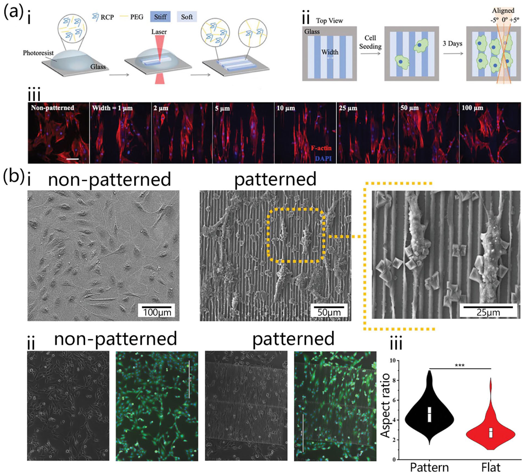
Typical methodology of using DLW controlling cellular morphology. (a) Characterization of cells seeded on patterned hydrogels. (i) Schematic illustration of the cell-adhesive hydrogel fabrication process. (ii) Schematic illustration of patterned hydrogel affects f-actin alignment. (iii) Con-focal images of cells seeded on patterned cell-adhesive hydrogels with pattern widths from 1 to 100 μm. 50 (b) Characterization of cells seeded on patterned polyacrylate scaffold. (i) Scanning electron microscopy and (ii) immunofluorescence staining microscopy of cells grown on glass substrate and patterned scaffold. (iii) Aspect-ratio of cells growing on the patterned scaffold and substrate. 48
Lithography
Lithographic techniques, originally developed for microelectronics, 51 have been adapted for CTE to create patterned substrates that mimic the natural ECM while presenting novel topographical cues to cells.52,53 The lithography process typically involves transferring a pattern onto a substrate through selective exposure of a photosensitive material.54,55 Upon exposure, the substrate undergoes a chemical change that enables the selective removal of either the exposed or unexposed regions, depending on whether a photo-crosslinkable or photodegradable substrate is used. Conventional photolithography utilizes ultraviolet (UV) light to transfer patterns from a photomask to a photoresist-coated substrate (Figure 3(a)).56,57 It is widely used with hydrogels because their lower modulus compared to solid cell culture scaffolds makes it challenging to apply topographical cues using machining methods. Unlike DLW employs near-infrared light, photolithography requires high-energy photons to activate the photoinitiator. This results in reduced light penetration, limiting pattering to thin material layers.58,59 However, the resolution of photolithography is limited by light diffraction. To achieve finer features, techniques like electron beam lithography (EBL) and soft lithography have been developed. EBL utilizes a focused electron beam to directly write patterns onto a resist, enabling nanoscale resolution and facilitating the study of cellular responses to intricate topographical cues.60,61 Soft lithography encompasses methods like microcontact printing and replica molding, typically using elastomeric stamps or molds made from materials such as polydimethylsiloxane (PDMS) or polyurethane acrylate (PUA). 62 These techniques provide advantages in simplicity, cost-effectiveness, and material compatibility, making them well-suited for biological applications (Figure 3(c)). Microcontact printing enables the patterned transfer of bioactive proteins, such as the controlled deposition of laminin, which influences cell morphology through biophysical cues. 63 These cues ultimately act through mechanotransduction pathways to regulate cytoskeletal architecture (Figure 3(d)). Replica molding, including nanoimprint lithography, involves transferring nanoscale features from a mold onto a thermoplastic polymer or UV-curable resin via heating or UV exposure. 64 This method is particularly advantageous for large-area, high-precision, and uniform patterning, such as nanoimprinting of polystyrene (PS) dots produced through nanoimprinting having diameters ranging from 103 to 533 nm. 65

Lithography fabricated substrates and cellular responses. (a, b) Brightfield images of photomask transparencies used to generate photopatterns in photodegradable hydrogels. Scale bars, 1 mm. 66 (c) Cellular alignment within replica molding fabricated PICO substrates. 12 (d) The organization of actin cytoskeleton in NIH 3T3 cells on microcontact printed patterns. 67
Etching
Etching is a subtractive process that creates topographical features on material surface by selectively removing material through physical or chemical means. Etching without a mask, also known as surface roughening, typically generates random topographic patterns. These patterns alter the material’s hydrophilicity or hydrophobicity, which can effectively regulate cell adhesion. 68 To achieve well-defined topographic cues, a mask is required to protect specific areas of the material, analogous to the masking process in lithography (Figure 4(a)). Chemical etching relies on the selective dissolution of a substrate material using chemical etchants. A common method is wet chemical etching, which involves immersing the substrate in a liquid etchant. Selectivity is achieved by masking specific areas of the substrate with a resistant material. For instance, silicon substrates can be etched using tetramethylammonium hydroxide (TMAH) or potassium hydroxide (KOH) in conjunction with lithography-fabricated masks. 69 In one study, polycaprolactone (PCL) served as a sacrificial layer on a thermoplastic polyurethane (TPU) substrate, which was etched with sodium hydroxide (NaOH) to create topographical edges ranging from 13 to 356 μm in width and 4 μm in depth. 70 Although wet etching is straightforward and cost-effective, it often lacks the precision and anisotropy necessary for intricate or smaller features. Physical etching, on the other hand, removes material through physical processes such as sputtering or ion bombardment. Ion beam etching (IBE) directs a focused ion beam at the substrate, ejecting surface atoms upon collision. 71 Moreover, reactive ion etching (RIE) integrates both physical and chemical processes. Accelerated reactive ions sputter the substrate surface while reacting with the material to form volatile byproducts that are subsequently removed. 72 Plasma etching, similar to RIE but generally less directional, utilizes a partially ionized gas (plasma) that contains ions, electrons, and neutral species to etch the substrate. 73 These physical and physicochemical methods provide greater precision and control over feature size and anisotropy compared to wet chemical etching, making them suitable for more complex microfabrication applications in CTE.74,75

(a, i) SEM of non-etched or plasma-etched scaffolds. 76 (a, ii) Schematic and SEM images of RIE-etched microgroove and microbridge substrates, alongside phase contrast microscopy images of cell-seeded substrates. 77 (b) Fabrication schematics illustrating microgroove patterning in stretched PCL and SEM images of flat and stretched PCL membrane. (b,a) Two-roll milling, (b,b) heat pressing and (b,c) uniaxial stretching. 78 (c) Cardiomyocyte growth at days 1, 4, and 7 (c, i) on Petri dishes, (c, ii) aligned nanofiber membranes, and (c, iii) printed inside aligned 3D nanofiber scaffolds (scale bar = 200 μm). 79
Self-organization
Self-organization utilizes the physical and chemical properties of the materials themselves to spontaneously form some patterned structures.80,81 This bottom-up approach, requiring minimal external intervention, is a powerful tool for fabricating topographies that mimic the complex architecture of biological tissues.82,83 For example, PCL is a semi-crystalline polymer comprising both amorphous (disordered) and crystalline (ordered) regions. The degree of crystallinity influences tensile strength; higher crystallinity generally correlates with increased strength. When PCL is stretched, the amorphous regions, which lack the structural integrity of the crystalline domains, deform to a greater extent, leading to the formation of grooves along the axis of strain (Figure 4(b)). 84 In addition, liquid crystals exhibit properties of both liquids and crystals, characterized by their unique molecular organization. These elongated, polar molecules typically align along their long axes, creating ordered structures. The orientation of liquid crystal is significantly influenced by substrate contact. Rubbing polyimide (PI)-coated glass substrates is the most common method for inducing liquid crystal alignment. Recently, liquid crystalline networks have emerged as promising cell-instructive materials capable of guiding cell alignment and promoting the formation of well-defined muscle fibers. 85
Electrospinning
Electrospinning is a versatile technique widely used for fabricating fibrous scaffolds ranging from nano- to microscale that provide topographical cues influencing cellular behavior. The process utilizes a high-voltage electric field, ranging from thousands to tens of thousands of volts, to a polymer solution or melt. When the electric field exceeds the solution’s surface tension, a fine polymer jet is formed. As the jet travels, the solvent evaporates or solidifies, resulting in nano- or micro-diameter fibers collected on a receiving device. 86 These fibers accumulate into non-woven mats with high surface area-to-volume ratios, effectively mimicking fibrous ECM structures. Moreover, the topographical characteristics of electrospun scaffolds, such as fiber diameter, alignment, and porosity, can be precisely controlled by manipulating parameters including polymer concentration, viscosity, voltage, flow rate, needle-collector distance, and collector motion.87–89 This level of control enables researchers to engineer scaffolds with specific mechanical and topographical cues that influence cellular adhesion, proliferation, differentiation, and migration.90,91 However, since the formation and patterning of fibers occur simultaneously during the fiber production process, it is challenging to achieve complex geometrical configurations and fiber orientations. Various electrospinning-derived methods have been explored to create topographical cues that mimic natural structures. Aligned electrospinning, for instance, employs a high-speed rotating drum collector to induce the formation of an oriented fiber membrane. Aligned electrospun fibers can direct cellular orientation and elongation, promoting anisotropic tissue structures (Figure 4(c)). This alignment is crucial in applications such as nerve regeneration,92,93 where fibers direct neurite outgrowth, and CTE,94,95 where fiber alignment influences CMs contraction. The coaxial electrospinning technique utilizes a coaxial nozzle to deliver core and shell solutions from the center and periphery, respectively, producing composite fibers with a core-shell structure. 96 This method enables the combination of shell materials such as extracellular matrix protein with low mechanical properties, with high modulus core materials like PCL, thereby fabrication CTE scaffolds exhibit both bioactivity and suitable mechanical properties. 97 Yarn electrospinning involves twisting the nanofibers to form fiber bundles with increased diameters. 98 Nanofibrous hydrogel yarns, which resemble the high anisotropy and uniaxial alignment of native myocardium, are considered ideal for constructing engineered cardiac tissue. 99 To better replicate the topographical cues of myocardial fibers in the natural heart, a focused rotating jet spinning method has been developed. This technique rapidly forms polymer micro- and nanofibers using centrifugal jet spinning, then focuses and patterns these fibers through controlled airflow to reconstruct the heart’s complex anatomical structure. 100 By combining the rapid fiber construction capabilities of electrospinning with the intricate architecture of the natural heart, this technology advances the goal of myocardial tissue engineering toward ultimately reconstructing the heart.
3D printing
3D printing includes various techniques, such as inkjet printing, digital light processing, extrusion printing, freeform reversible embedding printing, and selective laser sintering (Figure 5(a)). Each techniques fabricate structures with defined 3D architectures via sequential material deposition, guided by digitally designed models. Recent advances have enabled the development of multi-ink 3D printing systems, thereby allowing the creation of a single 3D structure composed of heterogeneous components (Figure 5(b)). In CTE, 3D printing enables the creation of scaffolds with well-defined architectures that replicate the intricate structures of native tissues. 101 By controlling printing geometries and parameters, researchers can modulate topographical cues within scaffolds, thereby enabling adaptation to diverse biomanufacturing requirements, simulating the topographic cues of natural tissue (Figure 5(c)). Studies have demonstrated the 3D printing of scaffolds that replicate skeletal,102–104 vascular,105,106 and cardiac structures.107,108 The scaffolds used for CTE should provide the cells with the opportunity to form tight connections and enable sufficient electrical coupling (Figure 5(d)). However, pre-fabricated complex scaffolds with porous structures and curved surfaces present challenges for cell seeding. Insufficient cell spreading on the scaffold may occur during gravity-based deposition. To address this issue, traditional 3D fabrication techniques have been enhanced with bio-inks composed of cells or cell-biomaterial mixtures. This approach, known as 3D bioprinting, is a promising technique for creating complex 3D extracellular topographical microenvironments. 109 A key advantage of 3D bioprinting is its ability to generate scaffolds with multiple extracellular structural environments. For instance, in cardiac bioprinting, various components, including the myocardium, epicardium, coronary arteries, and valves, can be fabricated by switching bio-inks and incorporating appropriate cell types (Figure 5(e)). 110

3D printing techniques and fabricated scaffold application in CTE. (a) Schematic illustrations of various 3D printing technologies. 111 (b) Illustrations of PEGDA inks and 3D structures produced by the composable-gradient DLP printing technique. 112 (c) 3D-printed biomimetic scaffold for CTE. Morphology of (i) natural myocardial fiber, (ii) PCL scaffold, (iii) seeded cardiomyocytes. 113 (d) The effects of different parameter 3D-printed scaffolds on the electrical activities of cardiomyocytes. (i) Schematic and SEM of cellular bundle formation, (ii) fluorescence micrographs of calcium transients, (iii) quantification of calcium transients in different shape scaffold. 114 (e) CAD rendering of printed left coronary artery structure and printed left coronary artery. Scale bars are 5 mm. 115
Theoretical basis of how cells sense and respond to topographical cues
Cellular perception and interpretation of topographical features have become key factors in governing cell behavior, a process known as contact guidance. 116 This process, termed contact guidance, involves complex interactions between cells and the ECM or biomaterials. However, the precise mechanisms by which cells orient and migrate in response to topographical cues have remained elusive for many years.
Focal-adhesion model
Ohara and Buck initially proposed that focal adhesions are crucial for cellular orientation in response to extracellular topographical cues. 117 At the heart of focal adhesion complexes primarily comprise integrins, heterodimeric transmembrane receptors that bind to ECM proteins, including fibronectin, collagen, and laminin. Intracellularly, integrins interact with structural proteins (e.g. talin, vinculin, paxillin) and signaling molecules (e.g. focal adhesion kinase (FAK), Src family kinases) that connect to the actin cytoskeleton. 118 Nano- and microscale topographical features can modulate integrin distribution and clustering, thereby influencing focal adhesion composition and size. Recent studies indicate that physical constraints from surrounding materials can limit focal adhesion maturation. Actin stress fibers, anchored at these adhesion sites, align along the substrate orientation, thus converting topographical cues into anisotropic traction forces that guide cellular orientation and migration. 119
Membrane curvature hypothesis
When cell membranes interact with nanoscale structures, they experience localized deformation through bending and stretching. This deformation recruits and activates curvature-sensitive proteins, particularly BAR (Bin/Amphiphysin/Rvs) domain-containing proteins. These banana-shaped proteins preferentially bind to curved membranes, stabilizing existing curvature or induce new curvature. 120 Upon recruitment, BAR domain proteins interact with actin regulatory proteins, including the Wiskott-Aldrich syndrome protein (WASP) and the actin-related protein 2/3 (Arp2/3) complex, initiating new actin filament formation. 121 The reorganization of the actin cytoskeleton in response to membrane curvature is crucial for maintaining cell shape and establishing polarity. During cell polarization, increased membrane curvature in specific regions promotes localized actin reorganization, facilitating the development of specialized structures, such as the epithelial cell apical brush border.
Energy-demanding view
The cytoskeleton, comprising actin filaments, microtubules, and intermediate filaments, is essential for cellular adaptation to microtopography. In 1976, Dunn and Heath showed that fibroblasts cultured on glass fibers (<100 μm in diameter) aligned along the fiber’s long axis, and hypothesized that cytoskeletal components fail to assemble or function effectively in bent conformations. 122 Cells adhering to ECM experience continuous morphological fluctuations, reflecting cytoskeletal remodeling. To minimize energy expenditure, cells prefer to utilize existing cytoskeletal structures rather than synthesize new components during shape and functional adaptations. For instance, Shishvan et al. proposed that cellular energy remains relatively constant over hours to days in non-dividing cells. 123 They discussed how cells spread along fibronectin-coated parallel stripe patterns to avoid forming adhesions on non-adhesive areas, which consume high energy, 124 a phenomenon they termed “gap avoidance.” Similarly, Werner et al. suggested that cells unable to avoid bending exhibit increased energy-demanding myosin light chain (MLC) phosphorylation, which explains their tendency to orient along fiber axes to minimize the energetic cost of maintaining curved morphologies. 125
Overall, when topographical cues come to cellular scale, understanding cellular responses to topographical cues requires a more macroscopic perspective, and recent computational models have enhanced our predictive capabilities in this field.
Impact of microscale topography on cardiomyocyte behavior
The response of CMs to environmental topographical cues is well-documented through extensive research involving various surface patterns, including grooves, ridges, and microfibers. 126 These micro-topographical cues from supporting materials significantly influence cell function and enable the biomimicry of the natural ECM, providing mechanical and architectural signals that enhance cell function.
Micro-grooved substrates, comprising parallel ridges and grooves at the microscale (typically a few to several tens of micrometers in width and depth), are fabricated using techniques such as photolithography, chemical etching, micro-imprinting, and 3D printing. These substrates significantly influence CMs orientation and elongation, promoting anisotropic alignment that mimics the architecture of native heart tissue. Studies have shown that human pluripotent stem cell-derived CMs (hPSC-CMs) cultured on PDMS substrates with 5 μm grooves and 20 μm wide ridges exhibit aligned morphology and uniform contraction along groove orientation. 127 Similarly, neonatal rat CMs demonstrate comparable elongation and orientation patterns along parallel groove directions, despite species differences from hPSC-CMs. 128 The aligned morphology of CMs is attributed to the directionally assembled components of the cytoskeleton. CMs grown on parallel micro-patterns demonstrate significantly enhanced alignment of myofibril-associated proteins, including F-actin and α-actinin, with sarcomere structures oriented parallel to the grooves. At the same groove depth, CMs exhibit increased cell area and alignment, resulting in most regular contractions at topographical edges compared to borders. 70 Notably, linearly oriented, myofiber-like myocardium structures demonstrate more than tenfold greater contraction compared to randomly oriented myocardium. 129 Moreover, micro-groove topography modulates gene expression profiles in CMs. Comparative analyses reveal upregulation of cardiac-specific genes in cells cultured on micro-grooved substrates compared to flat controls. hPSC-CMs cultured on grooved surfaces show significantly increased expression of ion channel genes (CACNA1C, KCNH2, RYR2, SERCA2A, LRRC39) and structural genes (MYL2, MYH6, MYH7, TNNT2), indicating enhanced maturation under micro-grooved conditions. 127 In addition, short microfibers, produced through advanced materials processing, provide 3D topographical cues that mimic the fibrous nature of cardiac ECM. Matthew et al. observed the interaction between CMs and microrod structures in a 3D hydrogel environment, 130 which significantly upregulated genes encoding adrenergic receptor beta-1, SERCA2, CARP, and COX8H. The enhanced expression of SERCA2, a protein crucial for intracellular calcium cycling, may explain the distinct beating patterns observed in CMs attached to microrods. These findings suggest promising directions for developing advanced biomaterials and scaffolds in CTE, potentially improving therapeutic outcomes for cardiac repair and regeneration.
Role of nanoscale topography in cardiomyocyte development
Focal adhesions (FAs) are primary sites where multiprotein complexes link substrates to the cytoskeleton. 131 During CMs adhesion to substrates, integrin binding to ECM components initiates the recruitment of core adhesion proteins, forming focal adhesion complexes. CMs exhibit two distinct types of FAs: peripheral focal adhesions (pFAs), which laterally associate with myofibrils, and costameres, which connect with sarcomeres. 132 Studies have demonstrated that the spatial organization of FAs plays a crucial role in cellular response to nano-topographical cues, 119 with defects or mutations in FA proteins potentially leading to cardiomyopathies. 133 Nano-topographical features that match the dimensions of focal adhesion complexes mainly affect FAs distribution and maturation, 65 influencing CMs behaviors, including cell spreading, cytoskeletal remodeling, and contractile function.
Nanofibrous scaffolds, primarily fabricated via electrospinning, provide a biomimetic environment that replicates the fibrous architecture of cardiac ECM. CMs cultured on these substrates typically align along the fibers, facilitating anisotropic electrical conduction and coordinated tissue contraction.134–136 For example, Werner et al. demonstrated that hiPSC-CMs seeded on aligned nanofiber sheets exhibited greater elongation compared to those on randomly distributed nanofibers. 125 On aligned wrinkled surfaces, CMs displayed anisotropic pFAs orientation parallel to the wrinkle direction, accompanied by enhanced pFA maturation. 137 Moreover, previous research has established that FAs are linked to actin stress fiber remodeling through mechanical signaling pathways. 138 This suggests that oriented and mature pFAs are prerequisites for actin reinforcement in CMs, potentially initiating myofibril remodeling and morphological changes. Further investigations demonstrated that CMs cultured on parallel nanogrooved substrates exhibited an anisotropic distribution of both FAs and actin filaments along the groove orientation, leading to a rod-like cellular morphology. This elongated morphology closely resembles that of mature CMs in vivo and enhances the formation of gap junctions, which are crucial for synchronized contractile function. 139 HiPSC-CMs on aligned nanofiber sheets demonstrated enhanced elongation, rod-like sarcomere structure, and elevated expression of cTnT and MLC-2v. 125 These proteins are crucial for regulating calcium-mediated contraction, with cTnT facilitating calcium-sensitive muscle activation and MLC-2 phosphorylation enhancing calcium sensitivity for more efficient contraction. For example, Balashov et al. used confocal laser scanning microscopy to observe that CMs on suspended nanofibers wrapped around the fibers, forming a sheath structure with myofibrils aligned along the fiber orientation near cell-material interfaces. 140 In contrast, fibroblasts showed only partial wrapping of the nanofibers, demonstrating different behavioral responses. This distinct behavior can be attributed to the unique attachment mechanism of CMs: they connect to the ECM not only through FAs but also via costameres that align with sarcomeres and traverse the myofibrils.141,142 This provides CMs with multiple attachment points to the substrate, stabilizing cell-ECM interactions.
Moreover, when cultured on suspended fibers, the costameres mature at the cell-material interface and serve as anchors to initiate myofibril formation, positioning the fiber centrally within the myofibril structure.140,143 For instance, Kitsara et al. investigated CMs behavior on plasma-created polystyrene substrates featuring nano-island topography with diameters ranging from 35 to 200 nm. 144 Their findings revealed that CMs preferentially spread on 35 nm nano-island surfaces, exhibiting elongated morphology compared to those on 200 nm topographies. Similar observations were made with nano-dot arrays (10–200 nm diameter), where cells showed reduced spreading area on surfaces with dots larger than 100 nm. 145 Their study also found that lower expression of vinculin and higher expression of PAI-1 proteins in H9C2 on larger nano-dots arrays, indicating larger diameter nano-dot arrays can reduce cell attachment and are associated with myocardial fibrosis. As the scale of nano-dots increased, iPSCs cultured on them were less likely to differentiate. 146 Further analysis of H9C2 demonstrated lower vinculin expression and higher PAI-1 protein levels on larger nano-dot arrays, suggesting that increased dot diameter compromises cell attachment and may contribute to myocardial fibrosis. 147 Additionally, larger nanodot scales inhibited the differentiation of iPSCs. The study also revealed diameter-dependent nitric oxide (NO) release patterns: CMs on 200 nm dots initially secreted high levels of NO on day 1, which subsequently led to decreased endothelial nitric oxide synthase (eNOS) expression and reduced NO release in following days. This finding has significant implications for cardiac stent design, as NO plays a crucial dual role in ischemia-reperfusion injury—protective during ischemia but potentially harmful during reperfusion due to peroxynitrite formation. Based on the differential adhesion responses of CMs to nano-dot arrays, researchers developed specialized plates to guide hiPSC-CM orientation. 148 In this study, comprehensive gene expression analysis was conducted, examining markers related to myosin heavy and light chains, cardiac troponins, ion channels, calcium transporters, mitochondrial function, vascular regeneration, and fatty acid metabolism. The results demonstrated that aligned substrates promoting cardiomyocytes orientation enhanced cellular maturation, providing a more representative platform for gene expression analysis, motility assessment, and drug evaluation compared to traditional animal models.
Application of topographical cues on cardiomyocytes
Co-engineering of nano and micro surface topography
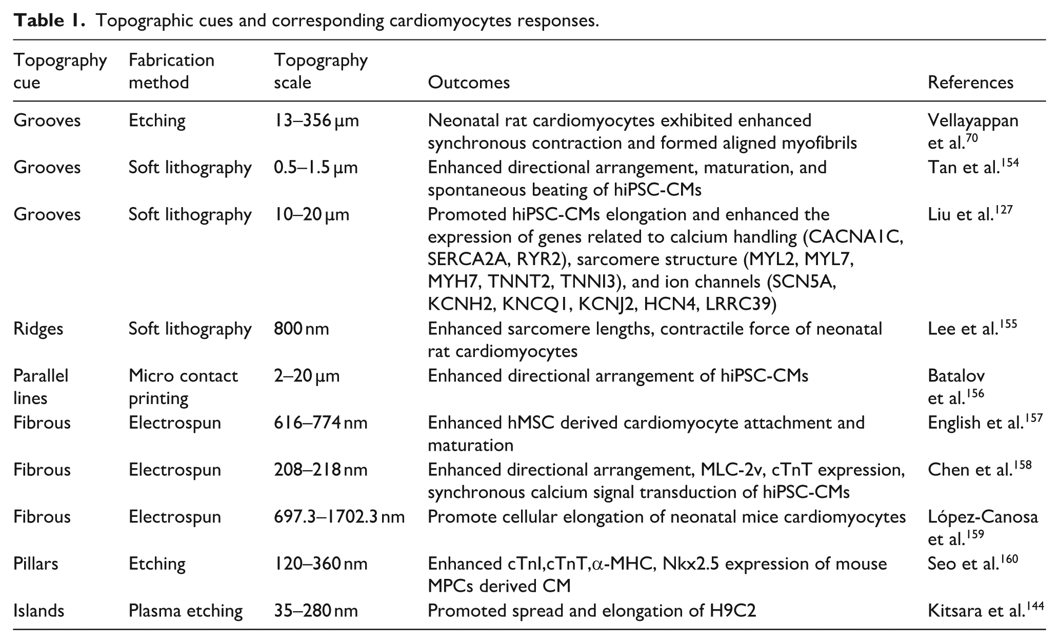
Nano- and micro-scale topographical cues significantly influence cellular behaviors in CMs. Nano-topographical features interact directly with cellular membrane proteins, such as FAs components and BAR domain proteins, affecting processes such as adhesion, orientation, and spreading.121,149 In contrast, micro-topographical, ranging from a few to several 100 µm, primarily influence larger-scale cellular processes, including elongation and overall alignment.56,63 Table 1 presents the effects of micro- and nanoscale topographical cues on cardiomyocytes. The co-engineering of nano- and micro-scale topographies on a single scaffold creates a composite cue that can simultaneously influence both microscale and nanoscale cellular behaviors, 150 synergistically promoting CMs organization and maturation.151–153 A study demonstrated this effect by establishing polystyrene (PS) nanodots on an oriented wrinkled surface, which resulted in enhanced expression of cardiac maturation-related genes, including cTnT and MyoG. 65
Topographic cues and corresponding cardiomyocytes responses.
Co-engineering of surface topography and biochemical cues
In addition to integrating multi-scale topographical cues, the interplay between physical cues and biochemical signals, such as ECM components (e.g. laminin, fibronectin, and collagen), is crucial for directing CMs maturation and the formation of functional myocardium. Microcontact printing techniques enable the introduction of patterned biochemical cues onto cardiac patches, providing combined topographical and biochemical guidance. For instance, micro-imprinted fibrin induced patterned spreading of CMs, leading to regular action potential conduction and enhanced contraction stress. 161 In another study, gelatin- and Matrigel-coated electrospun polyurethane fibers with a diameter of 200 nm were used to guide the alignment of human-induced pluripotent stem cell-derived cardiomyocyte (hiPSC-CM). 158 Interestingly, cardiac maturation markers such as cTnT and MLC-2v expression showed no significant differences between oriented nanofibers modified with gelatin or Matrigel.
Heart-on-a-chip
Recent advancements in understanding CMs responses to external environments have facilitated the integration of multi-scale topological and biochemical cues in the fabrication of heart-on-a-chip devices,162,163 cardiac patches,164,165 and biohybrid machines.166,167 For instance, structural colors arise from the interaction of light with nanostructured surfaces, resulting from phenomena such as interference, diffraction, scattering, reflection as light interacts with material surface structures. 168 Shang et al. fabricated isotropic inverse opal substrates with oriented porous structures that guided the development of mature cardiac tissue-like aligned CMs morphology. 169 These microstructures, which generated structural colors, proved bio-indurable for long-term, non-invasive tracking of CMs behavior under various stimulations. 170 Moreover, the integration of 3D-printed micro-topological cues with electrospun nanotopographical elements has been shown to fabricate composite scaffolds. A biomimetic structure was assembled through a modular stacking approach to develop heart-on-a-chip platforms that recapitulate the hierarchical architecture of native cardiac tissue. 9 When incorporated into GelMA-based 3D cardiac tissue constructs, the platform exhibited enhanced efficacy in drug screening applications compared to conventional 2D systems. Another approach utilized tunicate cellulose nanocrystals (TCNCs) mixed with GelMA to create structurally colored substrates for heart-on-a-chip devices. 171 Compared to PDMS cardiac films, the anisotropic alignment of TCNCs was achieved by applying shear stress before photo-crosslinking the GelMA hydrogel precursor. These hydrogel cardiac films more accurately mimicked the ECM, resulting in more mature cardiac tissues and improved testing consistency with in vivo tests. However, the biodegradable nature of GelMA hydrogel necessitates on-the-spot fabrication, which may lead to variations in the structural color characteristics of the heart-on-a-chip device.
Cardiac patch
The development of cardiac patches for myocardial repair and regeneration is a key focus in contemporary biomedical research. These patches aim to restore both the structural integrity and functional capacity of damaged cardiac tissue post-infarction by providing mechanical support and facilitating the integration and maturation of transplanted CMs.172–174 Electrospinning has emerged as a versatile and efficient technique for fabricating cardiac patch scaffolds, capable of producing fibers with diameters ranging from nanometers to micrometers, thereby effectively mimicking the native cardiac tissue microarchitecture.175,176 A primary goal of utilizing electrospun scaffolds as cardiac patches is to develop anisotropic structures that guide CMs alignment, enabling sustained synchronized contraction throughout the scaffold matrix.135,177 For instance, research has demonstrated that electrospun polycarbonate-urethane (PCU) anisotropic scaffolds effectively facilitated the development of synchronized beating cardiac tissue. 178 Furthermore, given that natural cardiac tissue contractions are intrinsically linked to electrical signaling, conductive materials can be easily incorporated into electrospun scaffolds. 179 For instance, the integration of polypyrrole (PPy) into PCL scaffolds has successfully produced nanofibrous cardiac patches with enhanced conductivity. 180 Beyond electrical properties, these nanofiber sheets also promoted vascularization, which is crucial for the survival of transplanted CMs. Moreover, natural proteins, such as sericin, have been utilized to create fibrous topographic structures that support vascularization in cardiac tissues.
In adult cardiac tissue, mature CMs exhibit limited regenerative capacity following injury. The implantation of various cell types, including mesenchymal stem cells (MSCs), bone marrow-derived cells, and iPSC-CMs, presents a promising approach for restoring contractile function in infarcted hearts. Notably, nanofibrous topographical cues in electrospun cardiac patches have been shown to enhance the expression of cardiac-specific genes (cAt, cTnT, and β-MHC) in human MSCs, promoting their cardiomyogenic differentiation. 181 The implementation of topographical cues in cardiac patch design represents a sophisticated strategy with significant potential for cardiac tissue repair. Recent advances in incorporating these cues have focused on three primary objectives: controlling coordinated CMs contraction, promoting stem cell differentiation into CMs, and enhancing patch vascularization to improve functional outcomes in injured cardiac tissue.
Biohybrid machine
CMs, the contractile cells of the heart, are essential for creating bio-hybrid actuators due to their intrinsic ability to convert chemical energy into mechanical work.182,183 Herein, we explore the role of topographical cues in engineering CMs-based bio-hybrid machines. These cues, such as grooves, 171 ridges, 184 and patterned substrates, 148 mimic the anisotropic architecture of cardiac tissue, thereby promoting the alignment of CMs in a unidirectional manner and generating anisotropy forces. 79 Recent advances in CTE have successfully applied these principles. For example, Nawroth et al. engineered a bio-hybrid construct that mimics juvenile jellyfish musculature by fabricating a fibronectin pattern with a central ring and eight radiating branches on polydimethylsiloxane (PDMS) substrates using micro-contact printing. 185 When stimulated by an external electric field, the seeded CMs induced coordinated contractions that, coupled with the elastic properties of PDMS, resulted in biomimetic jellyfish-like locomotion. 185 Building on this work, the researchers developed more sophisticated bio-hybrid systems by analyzing ray muscle architecture and precisely modulating the contractile properties of the biomimetic fins through manipulation of serpentine topographical cue density, achieving complex bionic actuation. 186 Similarly, Shin et al. enhanced CMs maturation and alignment by employing controlled parallel hydrogel stripe topography on biomimetic fins, generating sufficient propulsive force for bio-hybrid locomotion. 187 The integration of topographical cues in bio-hybrid system fabrication represents a crucial advancement in CTE, effectively harnessing CMs’ contractile capabilities. These structural elements significantly influence cellular organization, maturation, and the overall mechanical performance of bio-hybrid constructs. Optimizing the design and implementation of topographical cue in bio-hybrid applications holds considerable promise for advancing regenerative medicine, drug screening platforms, and soft robotics technologies.
Challenges and prospectives
Aligned topographical cues have been extensively utilized to regulate CMs orientation, thereby enhancing the maturation and contractile direction of engineered cardiac tissues. However, the underlying mechanisms governing this orientational control remain poorly understood, occasionally resulting in misalignment between CMs orientation and the predetermined scaffold architecture. Furthermore, conventional biomaterials used for topographical patterning, such as hyaluronic acid (HA), gelatin, chitosan, PCL, PLGA, alginate, and GelMA, are frequently incompatible with autoclave sterilization, the most effective sterilization method. This limitation impedes the advanced preparation of scaffolds with intricate topographical features under standard conditions, thereby restricting the available processing methodologies.
The native myocardium exhibits complex transmural gradients in myocardium fiber orientation 188 and requires substantial oxygen perfusion, with CMs extracting 65%–75% of blood oxygen content, in contrast to 10%–25% in other tissues. 189 Therefore, engineered cardiac tissue constructs must incorporate both biomimetic 3D topographical cues and extensive vascular networks to achieve functional equivalence. Future research should prioritize developing 3D topographical features that replicate native myocardial architecture and enhance vascularization strategies in CTE.
Conclusion
Topographical cues have demonstrated a notable capacity to influence CMs orientation, adhesion, and maturation, rendering them indispensable for the development of biomimetic cardiac constructs. These findings possess substantial potential for advancing CTE, offering valuable insights into the design of next-generation biomaterials capable of guiding the formation of functional, mature cardiac tissue. Biomaterials featuring microfibrous topographical cues combined with surface nano-topographic patterns smaller than 100 nm not only promote proper cardiomyocyte adhesion but also mimic the native architecture of cardiac tissue. This structural design is more likely to contribute to the fabrication of thick, contractile cardiac muscle constructs capable of replacing impaired myocardial tissue. The future of CTE, propelled by topographical cues, will depend on continuous advancements in fabrication techniques, theoretical understanding, biomaterial innovation, and structural design. Collaborative efforts across disciplines—spanning materials science, biology, physics, and chemistry—will be essential for the creation of bionic cardiac tissues with improved pumping capacity. These developments are poised to accelerate the application of engineered cardiac tissues in bio-hybrid systems, cardiac regeneration, and drug toxicity testing, thereby paving the way for transformative advancements in both research and clinical practice.
Footnotes
Author contributions
Study design: Maoyu Qin, Ping Zhu. Data collection: Maoyu Qin, Xinyi Chen. Statistical analysis: all authors. Data interpretation: all authors. Manuscript preparation: all authors. Literature search: Maoyu Qin, Xinyi Chen. Funds collection: Ping Zhu.
Funding
The authors received no financial support for the research, authorship, and/or publication of this article.
Declaration of conflicting interests
The authors declared no potential conflicts of interest with respect to the research, authorship, and/or publication of this article.