
Abstract
Commercially available Dacron (woven polyester) grafts are used for routine open surgical repair of thoracic aortic aneurysms. Despite durable and biocompatible, these grafts do not reproduce the natural mechanical properties of the aorta. Therefore, the aim of this project was to develop an innovative graft that additionally exhibits physiological aortic compliance. To achieve this result, multi-layered tubular aortic grafts were created by electrospinning of a thermoplastic polyurethane. To reduce permeability, a gelatin-coating was added. Three groups (G1–3; n = 5) with varying layer designs were evaluated regarding the main mechanical properties of vascular grafts such as suture retention strength, permeability and static and dynamic compliance. G3, which combined electrospinning with a stable silicone-coated inlay was chosen for the fabrication of medical grade thermoplastic polyurethane grafts (Gm; n = 6). Dynamic compliance values of 19.68 ± 11.5%/100 mmHg (50–90 mmHg), 15.18 ± 8.7%/100 mmHg (80–120 mmHg) and 14.56 ± 7.4%/100 mmHg (110–150 mmHg) were achieved. The compliance was higher than for Dacron and ePTFE grafts and comparable to the normal sized ascending aorta of around 16%/100 mmHg in a healthy human and porcine aortic compliance of 14.3%/100 mmHg. Static compliance was successfully tested up to 350 mmHg. No significant changes in graft diameter or delaminations of the graft layers were detected after compliance testing. Therefore, by combining electrospinning with a durable inlay, both elasticity and recoverability are obtained, resulting in a promising alternative to the gold-standard in open-surgical treatment of thoracic aortic pathologies.
Introduction
The incidence of thoracic aortic aneurysms (TAA) is 5–10/100,000 patient years. More than half of these cases involve the ascending aorta and/or the aortic root, followed by the aortic arch and the descending aorta. Cardiovascular risk factors (e.g. arterial hypertension), anatomical risk factors (e.g. bicuspid aortic valve) and genetic risk factors (e.g. Marfan syndrome) can increase the likelihood of developing an aneurysm of the ascending aorta. However, many TAAs occur sporadically and remain idiopathic. When therapy is indicated, an open-surgical repair is generally considered the standard approach. 1
For the surgical replacement of diseased or damaged blood vessels, artificial grafts made of Dacron (woven polyester, polyethylene terephthalate, PET) and expanded polytetrafluoroethylene (ePTFE, Gore-Tex®) are widely used and have been commercially available for decades.2,3
The introduction of large-diameter vascular grafts in the mid-20th century significantly expanded treatment options for aortic aneurysms. Concerns, however, about the long-term performance of these grafts have emerged,4–7 particularly with regard to a compliance-mismatch and its consequences.8,9
In this context, compliance refers to the vessel’s ability to change diameter in response to pressure fluctuations. This property arises from the histological structure of the vessel wall, primarily composed of muscle cells, elastic fibers and collagen fibers. The ratio of these components varies along different segments of the aorta. Segments closer to the heart contain a higher concentration of elastic fibers in the tunica media, whereas further from the heart, the elastic fiber content decreases and collagen content increases. As a result, the ascending aorta, which originates directly from the left ventricle, exhibits the highest compliance among aortic segments, a phenomenon also known as the Windkessel effect. 10 During systole, the ascending aorta expands to accommodate roughly half of the stroke volume, while the remainder is directed peripherally; the stored volume is then released during diastole, contributing to efficient cardiac function. 11
Limited in vivo data on ascending aortic compliance have been collected by Tobey et al. 12 using intravascular ultrasound measurement (IVUS). In their study, 79 patients were examined with an average age of 53.4 years. The mean ascending aortic compliance was measured at 18.4% per 100 mmHg in patients with prior aortic pathology and 16% per 100 mmHg in a control subgroup. Reduced vessel compliance, and thus a diminished Windkessel effect, poses a particular challenge following surgical repair of the ascending aorta, as grafts used in these procedures typically exhibit noticeably lower compliance values. For instance, Tai et al. 13 reported compliance values of 1.8%/100 mmHg for Dacron and 1.2%/100 mmHg for ePTFE grafts in a flow model. 13 This compliance-mismatch between the native vessel and the aortic graft may lead to various long-term complications,11,14 including neointimal hyperplasia due to elevated wall stress and turbulent flow at the anastomotic site, 15 anastomotic aneurysms, 16 pseudoaneurysm formation 17 and increased left ventricular workload due to greater pressure differentials. 11 It has also been suggested that end organ function, such as renal and even cerebral function may deteriorate with time. 18 Thus, it appears crucial to continue research and advance the development of large-diameter vascular grafts that closely replicate physiological aortic function.
In this study, we developed a new large-diameter graft with significantly improved compliance compared to commercially available Dacron grafts. Electrospinning enables the fabrication of fibers with diameters ranging from micro- to nanometers, closely mimicking the extracellular matrix (ECM) of blood vessels. 19 This fibrous scaffold supports cellular growth while allowing high customizability in scaffold characteristics, such as the mechanical properties of the graft. Specific material selection and optimization of electrospinning parameters—including flow rate, voltage, needle-to-collector distance, and collector speed—enable variation of fiber diameter and pore size. The versatility of the electrospinning technique, along with the ideal scaffold structure it creates for cellular ingrowth, makes it suitable for a wide range of applications—from one of the most widely used techniques for fabricating biomimetic vascular grafts to various uses in regenerative medicine, such as tissue regeneration and wound healing. 20
To mimic the layered histological structure and properties of the aortic wall, a three-layer design was selected. Thermoplastic polyurethanes (TPU) were used for electrospinning due to their mechanical stability and high flexibility. A silicone-coated inlay was incorporated into the middle layer to enhance durability, while gelatin coating was added to improve graft biocompatibility and reduce permeability. Key metrics, including suture retention strength, permeability, and both dynamic and static compliance, were evaluated in this study.
Materials and methods
Electrospinning setup
An electrospinning setup with exchangeable rotating mandrels was developed as previously described (Supplemental Figure S1). 21 The setup consisted of a syringe pump, a rotating collector, a blunt needle mounted in a 3D-printed needle holder and a high voltage supply connected to the electrospinning-needle and the collector (Supplemental Figure S2). Humidity was controlled by constantly infusing dry air into the electrospinning box. The mandrels were 3D-printed (Ultimaker B.V., Utrecht, NLD) from conductive polylactic acid (PLA, Protoplant Inc., Vancouver, USA). To facilitate the removal of the graft from the collector, aluminum foil was tightly wrapped around it. To secure the collector within the electrospinning setup, a construction was built in-house, consisting of a central metal rod onto which the collectors were slid on (Supplemental Figure S3). The collector was powered by a stepper motor (Nanotec Electronic GmbH & Co. KG, Feldkirchen, DE) placed inside the electrospinning box. The stepper motor was connected to the collector via a v-belt. The electrospinning solution was loaded into a 20 mL syringe and connected to a syringe driver located outside of the electrospinning box (Chemyx Inc., Stafford, USA). Flowrate and needle diameter were used to vary fiber diameter and pore size of the electrospun layers. The needle was connected to the negative terminal of the high voltage power supply (Iseg Spezialelektronik GmbH, Radeberg, DE) and the mandrel to the positive terminal. In order to achieve a stable Taylor-cone formation, a voltage between 12 and 16 kV was applied to the needle and 0.5 kV to the collector.
Electrospinning solution and scaffold fabrication
For electrospinning, a 15% (w/w) solution containing 15 g TPU (Pellethane 2363 80AE, VELOX GmbH, Hamburg, DE) dissolved in 42.5 g N, N-dimethylformamide (DMF) and 42.5 g tetrahydrofuran (THF) (Sigma-Aldrich, St. Louis, USA) was prepared. Three different groups of grafts (Figure 1; n = 5 each) were fabricated with Pellethane using electrospinning. Gthree-layer (G1), Gcompliance (G2), Gsilicone (G3), depicted in Supplemental Figure S4. The process parameters of the graft groups are displayed in Table 1. All grafts have a three-layer structure in resemblance of the structure of the aortic wall. With the initial approach, G1 was created using solely the electrospinning technique. The three layers of G1 differed in fiber diameter and pore-size. The inner and outer layer were electrospun at a low flow rate and smaller needle diameter to reduce fiber diameter and pore size and thus reduce permeability. However, G1 didn’t meet the necessary mechanical properties for a durable aortic conduit. Therefore, the approach was modified by using two different collectors varying in diameter to create G2. G2 was manufactured with the same layer design as G1. Compared to G1, however, two collectors with different diameters (25 mm/30 mm) were used as templates. During the first half of the spinning process, the 25 mm collector was used. Midway through the manufacturing process, the graft was transferred from the 25 mm collector to the 30 mm collector. We hypothesized that using two collectors, different in size, may allow us to achieve a wavy or crimped structure of the grafts, enhancing their stability against pulsatile pressure during compliance testing.22,23 As blood vessels possess unique mechanical properties due to their composition of mainly elastin, collagen and muscle cells. Elastic fibers enable the vessels to stretch and subsequently recoil once pressure subsides. 24 The crimped microstructure of collagen fibers unfolds under initial pressure, extending to their full length to limit the distension of the vessel diameter. 25 Utilizing two different collectors allowed the G2 grafts to adopt a slightly wavy shape that accommodates easy dilatation before the electrospun fibers stretch and restrict further expansion. Although the results improved, G2 was still not a viable option for long-term, high-pressure use. As a result, the method was further refined by integrating a silicone coated inlay in combination with electrospinning to achieve the required compliance and stability necessary for an aortic implant. For G3, the inner and outer layer were electrospun and a silicone-coated inlay (Safetac®, Mölnlycke Holding AB, Göteborg, SWE) was added to the middle layer to increase graft stability and reduce graft compliance. After the inner layer was electrospun, the silicone-coated inlay was wrapped around the collector in a single layer, overlapping approximately half a centimeter. Electrospinning of the third layer was started immediately. G3 showed the most favorable results, which is why the method protocol was transferred to create Gm using the TPU Desmoan (Gm; n = 6). Gm were made of TPU (Desmopan 786 E, Covestro AG; Leverkusen, DE) according to the identical protocol. Since the molecular weight of Pellethane and Desmopan differed, a 18% (w/w) electrospinning solution was prepared by dissolving 18.6 g of Desmopan in 85 g of solvent (DMF: THF = 3:1, Sigma-Aldrich Co.). To reduce permeability of the grafts and improve future cell adhesion, a gelatin-coating was added. The electrospun grafts were immersed in a 2% (w/v) gelatin-solution (Gelatin from porcine skin, gel strength ~175 g Bloom, Typ A, Sigma-Aldrich Co.) at room temperature for 24 h. The grafts were then removed from the gelatin-solution, excess gelatin was taken off and the grafts were used for compliance testing. In the following, G1–3 and Gm were compared regarding their mechanical properties to demonstrate the progression from G1 to G3 and Gm, as well as the challenges that come with trying to create a durable aortic conduit with good compliance using electrospinning.

Overview of graft groups manufactured with the electrospinning method. Three different groups of grafts were created and subsequently compared regarding their mechanical properties. Thermoplastic polyurethanes (TPU) were used for electrospinning. The TPU Pellethane was used for electrospinning of G1–3. G1 and G2 were solely manufactured using electrospinning. For G3, a silicone-coated inlay was integrated in the middle layer of the graft. As G3 showed the most favorable results regarding mechanical properties, the TPU Desmopan was employed to create Gm, following the identical protocol.
Overview of electrospinning parameters for graft groups G1 to G3. Rpm = revolutions per minute, fr = flow rate, V = volume. All graft groups consist of three layers. G1 was produced with the 30 mm collector. A 20 G needle was used for the inner and outer layer, and 13 G for the middle layer. G2 was produced with two collectors. Midway through the electrospinning process the graft was transferred from the 25 mm to the 30 mm collector. Analog to G1, a 20 G needle was used for the inner and outer layer and a 13 G needle for the middle layer. G3 was produced with a silicone-coated inlay as the middle layer. The inner layer was created using a 13 G needle. In the middle of the process, the tailored silicone-coated inlay was wrapped around the graft. The outer layer was produced in the same manner as the inner layer.

Material characterizations and mechanical testing
The grafts were standardized to a length of 90 mm and weighed using a scale (KERN & SOHN GmbH, Balingen, DE) before and after gelatin-coating. To ensure uniform wall thickness of the grafts, tubular grafts were cut into segments and wall thickness determined at 30 measure points along the graft.
Fiber diameter was determined by scanning electron microscopy (SEM; Carl Zeiss Microscopy GmbH, Jena, DE) using the ImageJ software (ImageJ2, Version 2.9.0/1.53t). A sample was taken from each end of the tubular grafts before and after gelatin-coating. SEM images were evaluated with 1000× magnification and 200 different fiber measurements were conducted for each image.
Suture retention strength
For suture retention strength (SRS), tubular vascular grafts were cut into rectangular strips measuring 20 mm × 10 mm (GelweaveTM, Vascutek Ltd., Inchinnan, GBR; Gore-Tex® Stretch Vascular Graft, W. L. Gore & Associates, Inc., Newark, Delaware, USA). A suture was then placed 2 mm away from the edge of the sample. The thread was cut to 100 mm length and knotted up to four times. The loop was put around a bolt and the other end clamped into the tensile testing machine (Zwick-Roell GmbH & Co. KG, Ulm, DE) at 5 mm. The suture materials used were 4-0 Prolene (Ethicon®, Johnson & Johnson Medical GmbH, Norderstedt, DE) and CV-5-Gore-Tex® (W. L. Gore & Associates, Inc., Newark, Delaware, USA). Before testing, the wall thickness of all samples was measured at two points (Mitutoyo absolute, Mitutoyo Corp., Kawasaki, JP). The suture was pulled at a rate of 50 mm/min and the force leading to graft or suture failure was recorded.
Permeability
The permeability testing apparatus was designed in-house (Supplemental Figure S5). Rectangular samples of 30 mm × 30 mm were obtained from tubular grafts. The samples were inserted into the testing apparatus and securely sealed. To better mimic blood viscosity, a 40% (w/w) glycerine-solution (Glycerin Rotipuran® ⩾99.5%, p.a., wasserfrei, Carl Roth GmbH + Co. KG, Karlsruhe, DE) was used for testing. 27 Pressure ranging from 80 to 120 mmHg was applied to the samples using a glycerine column. Permeability was calculated from the liquid that passed through the sample in 1 min (mL × cm−2 × min−1). The following equation was used, where S represents the permeability of the sample, Q is the volume of glycerine-solution passing through and A is the cross-sectional area:
Compliance testing
The testing apparatus for the compliance testing was also designed in-house (Supplemental Figure S6). Similar to the permeability setup, a 40% (w/w) glycerine-solution was used for testing. The diameter change with increasing pressure was measured with a laser micrometer (LS 9000, Keyence Corporation, Osaka, Japan). Two sensors for the pressure measurements were installed in the flow loop (WIKA, Alexander Wiegand SE & Co. KG, Klingenberg am Main, DE). The grafts were put into the setup and fixed with PTFE tape and hose clamps. Subsequently, a constant amount of glycerine-solution was poured in. For dynamic testing of the Pellethane grafts, cyclic pulses were delivered at a rate of 10–20 per min with a 50 mL syringe filled with glycerine-solution. Measurements were conducted in ascending order at pressure ranges of 50–90 mmHg, 80–120 mmHg and 110–150 mmHg. Each graft was tested for 30 min. For the Desmopan grafts a pulsatile element was added to the compliance setup to increase the cyclic pulses to 60 min−1. To determine compliance values, the inner diameter (mm) of the grafts was calculated first with Rp as the inner radius under pressure, Dp the measured outer diameter under pressure and t the beforehand determined wall thickness of the graft:

Then the compliance (%/100 mmHg) was calculated with the following formula with R as the inner radius under pressure and p2 as the higher pressure in the investigated pressure range and p1 the lower pressure:

Static compliance was evaluated after dynamic compliance testing. Starting at 50 mmHg, pressure inside the compliance setup was increased with a 50 mL syringe filled with glycerine-solution. Static compliance was measured at ascending pressure levels for at least a minute each up to 350 mmHg. Pressure was increased until leakage of glycerine-solution through the electrospun graft walls was observed. As a control for our method and for comparison with the sources used, the compliance of the PET grafts utilized in this study was measured (Supplemental Figure S7).
The maximum pressure (Pmax) of each graft was determined as the highest pressure the grafts could withstand without leaking or delamination of the graft. Pmax was evaluated in the compliance testing setup after dynamic and static compliance measurements.
To detect any irreversible changes in graft diameter that occurred through compliance testing, the graft diameter was evaluated before and after testing.
Cytotoxicity assessment
Human fibroblast cells (FC) were extracted from the greater saphenous vein (GSV). Spare GSV segments were obtained from the cardiothoracic operating theater. Informed consent of the patients was acquired prior to surgery and approved by the ethics committee of Ludwigs-Maximilians-University Munich. Seeding-samples (∅ 2.5 cm) were cut out of an electrospun, tubular aortic graft (G3; n = 10) and sterilized for 1 h in 70 % alcohol (Clinic-intern pharmacy, LMU Klinikum Großhadern, Germany). Subsequently, the samples were transferred to two 6-well-plates (Falcon, Corning, NY 14831, USA) with complete endothelial cell growth medium (ECGM-Kit, PromoCell Gmbh, Heidelberg, Germany) and 1% Pen-Strep (Sigma Aldrich GmbH) for 24 h. The wells were seeded with FC at a density of 750.000 cells/cm2. 3.75 × 10⁶ cells were added to each well. A positive control (only cells) and a negative control (graft sample without cells) were implemented. ECGM was changed every 2–3 days. Cells were cultured for 10 days at 37°C and 5% CO2 (Inkubator APT Line TM CB, Binder GmbH, Tuttlingen, GER). After incubation, Live-Dead-staining was performed. 100 µL growth-medium was taken from each well and put in a 0.5 mL test tube. 1 µL of PI (propidium iodide, Sigma-Aldrich GmbH) and 0.5 µL of Syto9 (Syto®9 Green-Fluorescent Nucleic Acid Stain, Life Technologies GmbH, Darmstadt, GER) were added. The solution was carefully mixed and returned to the wells. Cells were stained immediately, and the further working process was conducted shielded from light. Samples were assessed with SEM before and after cell seeding and Live-Dead-staining was analyzed using fluorescence microscopy (AxioObserver; Carl Zeiss AG, Oberkochen, Germany).
Statistics
Statistical analysis was performed using GraphPad Prism Software (v10.0.3, GraphPad Software, LLC, La Jolla, CA, USA). Values were displayed as mean ± standard deviation (SD) unless otherwise stated. Testing for normal distribution was performed using the Kolmogorov–Smirnov Test. Subsequently a one-factor variance analysis was carried out. Post hoc analysis, corresponding to sample size and test was conducted to compare groups amongst each other. For direct comparison between two groups, a Student’s t-test for independent samples was applied. If a normal distribution was not observed, the Kruskal–Wallis test or Mann–Whitney test was employed. p-values < 0.05 were considered statistically significant.
Results
Material characterization and mechanical testing
Three-layered tubular aortic grafts were successfully fabricated. With a stable low rotation speed of the collectors, randomly spun fibers were produced. The mean fiber diameter varied due to changes in flowrate and needle diameter (Table 1). The mean fiber diameter for the inner layer was 1.43 ± 0.48 µm, for the middle layer 3.55 ± 0.62 µm and for the outer layer 1.72 ± 0.38 µm for the solely electrospun grafts (Figure 2(a)–(c)). Representative grafts were evaluated with SEM prior to further testing. After evaluation, most of the samples were found to be spun defect-free. Some samples showed beaded fibers or varying fiber diameters.

SEM images of representative electrospun grafts. (a) Inner layer of G1–G2. Electrospun fibers appear denser spun compared to the middle layer (b). (c) Image of an outer layer of G1–G2, analog to the inner layer. (d) Luminal side of a graft after gelatin coating, (e) extraluminal side after gelatin coating. (f) Cross-section of a G3 graft with a silicone-coated inlay incorporated into the middle layer of the graft. Inner and outer layer spun analog to image (b). (a–e) Scale bar = 25 µm. (f) Scale bar = 0.5 mm.
The added gelatin-coating of the grafts covered the inner and outer layer sufficiently (Figure 2(d) and (e)). A slight uneven distribution of gelatin can be observed on the extraluminal wall of the grafts (Figure 2(e)), as the samples were dried on the intraluminal side before evaluation with SEM. The silicone-coated inlay was implemented in the electrospinning process with a satisfactory result (Figure 2(f)).
Furthermore, graft thickness was determined from groups G1–3 and Gm as well as the Gore-Tex® and Dacron grafts for reference (Figure 3(a)). G1 reached an average thickness of 0.93 ± 0.04 mm and did not differ significantly from G2 with a mean thickness of 0.90 ± 0.07 mm (p = 0.0887). G1 and G2 were significantly thinner compared to G3 with a mean thickness of 1.37 ± 0.21 mm and the Desmopan grafts (Gm) with 1.30 ± 0.06 mm due to the inlay incorporated in the middle layer of the graft (p < 0.05). G3 and Gm did not differ significantly in sample thickness (p > 0.99). Compared to the Gore-Tex® samples with a mean thickness of 1.13 ± 0.15 mm, G1 and G2 showed a significantly lower (p < 0.05) and G3 and Gm no statistically significant difference in graft thickness (p = 0.08; p = 0.56). The Dacron samples measured a mean thickness of 0.62 ± 0.07 mm. The only electrospun grafts G1 and G2 (p = 0.003; p = 0.04), as well as groups G3 and Gm (p < 0.001) and the Gore-Tex® group reached significantly higher thickness in comparison.
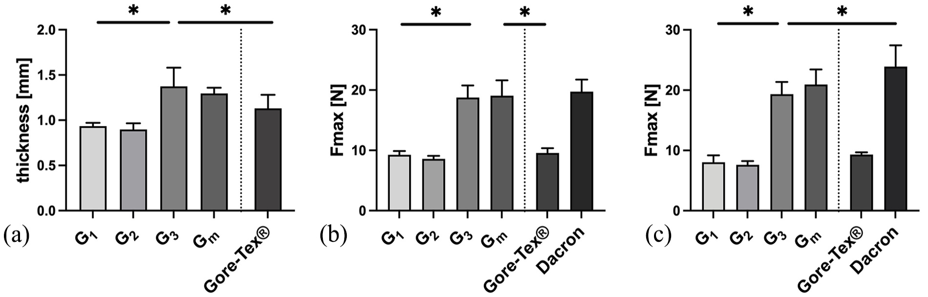
Graft thickness and suture retention strength. (a) Graft thickness of the tested samples (n = 28–36). G3 was significantly higher compared to the other electrospun grafts due to the silicone-coated inlay in the middle layer. Thickness of G3 was comparable to the Gore-Tex® grafts. Graft thickness of Dacron grafts was not measurable. (b) SRS with 4-0 Prolene sutures (n = 15–18). Group G3 reached values significantly higher than G1 and G2 and the Gore-Tex® grafts. G3 performed comparable to the Dacron grafts. (c) SRS with CV-5 Gore-Tex® sutures (n = 13–15). G3 reached significantly higher values than G1 and G2 and the Gore-Tex® grafts. Data displayed as mean ± SD.
Suture retention strength
Commercially available Gore-Tex® and Dacron (woven PET) grafts were used for comparison to evaluate the mechanical properties of the tubular electrospun grafts. The mean values for the suture retention strength of the electrospun grafts (G1–3, Gm) are shown in Figure 3(b) and (c). Both 4-0 Prolene and CV-5 Gore-Tex® sutures were used. In the 4-0 Prolene group, the Desmopan Grafts (Gm) had the highest suture retention strength of the electrospun grafts at 19.07 ± 2.54 N, which was not significantly different from the Dacron grafts, which had the highest overall value (19.74 ± 1.99 N; p > 0.99). No significant difference was seen between G3 and Gm (p > 0.99). G1 and G2 differed significantly from each other (p < 0.05) and no significant difference between G1 and the Gore-Tex® Grafts was objectified. The CV-5 Gore-Tex® group showed similar results. Gm achieved the highest value of the electrospun grafts at 20.94 ± 2.49 N and differed not significantly from the Dacron grafts (23.90 ± 3.54 N; p = 0.1612). G1 and G2 were again comparable to the Gore-Tex® graft. No significant differences were found between G1 and G2 in this group (p = 0.9690). Although G3 and Gm achieved significantly higher values than G1 and G2 overall due to the silicon-coated insert in the middle of the graft (p < 0.05), all electrospun grafts exceeded the suture retention strength requirements of 2 N and are therefore suitable for surgical application. 28
Permeability
All electrospun grafts (G1–3, Gm) remained permeable without gelatin-coating, with similar mean values for 80 and 120 mmHg for the groups G1–G3. Only Gm showed no permeability at 80 mmHg without gelatin-coating (Figure 4). Gore-Tex® and gelatin-coated Dacron grafts did not show any permeability at 80 and 120 mmHg. Mean permeability was highest in the G1 group with 10 ± 1 mL × cm−2 × min−1 for 80 mmHg and in the Gm group with 14 ± 4 mL × cm−2 × min−1 for 120 mmHg. However, no statistically significant difference between the electrospun grafts at the different pressure levels could be found. After the grafts were coated with gelatin, no permeability was detected at 80 and 120 mmHg.

Permeability measurements of G1–G3 before and after gelatin-coating as well as commercially used Gore-Tex® and Dacron grafts (n = 5). After gelatin-coating no permeability was detected in the electrospun grafts. Data displayed as mean ± SD.
Dynamic compliance
At the pressure range of 50–90 mmHg, G1 reached the highest compliance value with 47.83 ± 9.88%/100 mmHg (Figure 5(a)). In comparison, the mean compliance value for G2 at this pressure range was significantly lower with 22.46 ± 9.26%/100 mmHg (p < 0.05). G3 showed the lowest value with 7.13 ±2.20 mmHg%/100 mmHg (p < 0.05) (Figure 5(b)). At 80–120 mmHg, G1 could not be sufficiently tested due to a diameter increase beyond the cut-off of 50.55 mm of the measuring device. G2 reached a compliance of 23.08 ± 4.25%/100 mmHg which was significantly higher than G3 with 6.35 ± 2.17%/100 mmHg. In the last interval from 110 to 150 mmHg only grafts of the group G3 were able to be tested. A mean compliance value of 7.50 ± 2.97%/100 mmHg was reached.
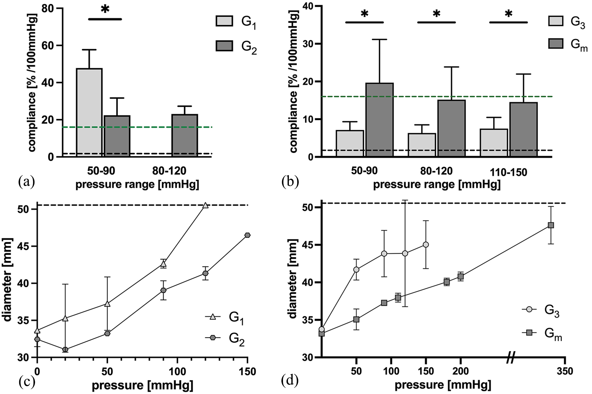
Dynamic and static compliance. (a) Dynamic compliance measurements G1 and G2. A significant higher compliance was detected in G1 (n = 3) compared to G2 (n = 3) in the range of 50–90 mmHg. In 80–120 mmHg only G2 could be sufficiently tested (n = 4). Green line: Physiological ascending aortic compliance. 19 Black line: Compliance of commercially available Dacron and Gore-Tex® grafts. 21 Compliance of groups G3 and Gm in comparison. (b) Dynamic compliance values of G3 (n = 5) and Gm (n = 5–6). Significantly higher compliance values were reached with Gm in all pressure ranges. Green line: Ascending aortic compliance. 19 Black line: Compliance of Dacron and Gore-Tex® grafts. 21 (c) Static compliance of G1 (n = 1) and G2 (n = 1). Black line: Cut-off of measuring device. (d) Static compliance values of G3 (n = 2–4) and Gm (n = 5). Black line: Cut-off of measuring device. Data displayed as mean ± SD.
Desmopan grafts (Gm) were fabricated analog to G3 and dynamic compliance was tested (Figure 5(b)). At the pressure of 50–90 mmHg, the Gm grafts reached a mean compliance value of 19.68 ± 11.46%/100 mmHg. At 80–120 mmHg the compliance was 15.18 ± 8.67%/100 mmHg and for the range of 110–150 mmHg the mean value was 14.56 ± 7.41%/100 mmHg. Compared to the G3 grafts, compliance was significantly higher in all pressure ranges (p < 0.05).
Static compliance and maximum pressure
Static compliance was evaluated following dynamic compliance testing (Figure 5(c) and (d)). For the Pellethane group (G1–G3), delamination occurred in some cases during dynamic testing. Therefore, not all grafts were available for static compliance testing. Especially G1 and G2 were prone to delamination. During testing of group G1, the grafts constantly increased in diameter until the cut-off of the measuring device (50.55 mm) was reached at 120 mmHg. G2 reached the cut-off at 150 mmHg. G3 on the other hand were less prone to irreversible diameter increase and delamination and were able to be tested up to 150 mmHg and did not reach the cut-off value. In the Desmopan group (Gm) static compliance values were evaluated up to 270 mmHg for all grafts of the group. No case of delamination or irreversible diameter increase occurred.
Following static compliance testing, pressure in all grafts was increased until leakage or delamination occurred and noted as maximum pressure (Supplemental Figure S8). G1 reached a mean maximum pressure of 149.02 ± 9.46 mmHg and did not differ significantly from G2 (G2 = 166.85 ± 26.64; p > 0.99). G1 and G2 measured similar values compared to G3 with a mean maximum pressure of 199.01 ± 15.26 mmHg (p = 0.26; p = 0.91). Gm reached the highest value overall with 329.38 ± 30.10 mmHg on average and differed significantly from G1 and G2 (p < 0.05).
Graft diameter
To evaluate irreversible diameter changes after compliance testing, graft diameter was determined before and after compliance testing (Figure 6). In the Pellethane group (Figure 6(a)–(c)), graft diameters from all groups (G1–3) showed a significant increase in graft diameter over the time of compliance testing. G1 increased from a mean diameter of 33.46 ± 0.61 mm before compliance testing to 38.02 ± 5.32 after testing (p < 0.05). G2 recorded a mean diameter increase from 32.75 ± 2.90 mm to 42.40 ± 0.91 mm (p < 0.05) and G3 from 33.72 ± 0.80 mm to 36.43 ± 2.72 mm (p < 0.05).

Diameter measurements of G1–G3 before and after compliance testing. A significant increase in diameter after compliance testing was observed in G1–G3 (a–c). In Gm (d) no significant diameter increase was detected.
In the Desmopan group Gm (Figure 6(d)) the mean diameter before compliance testing was 33.18 ± 1.49 mm and after testing 33.28 ± 0.82 mm. No statistically significant difference in diameter was found (p = 0.1364).
Cytotoxicity assessment
To evaluate cell proliferation and distinguish between living and dead cells, TPU scaffolds were examined with SEM and a Live-Dead assay was performed (Figure 7). Representative figures are displayed. Figure 7(a) demonstrates the positive control (cells only) and Figure 7(b) the negative control (TPU scaffold only). As TPU have a high level of autofluorescence when staining for immunofluorescence, Figure 7(b) displays TPU fibers stained with Syto9. Figure 7(c), however, clearly shows a TPU scaffold with gelatin-coating and primarily viable fibroblastic cells. Nearly no dead cells are visible (red dots). Furthermore, SEM images of the scaffolds were analyzed. Figure 7(d) and (e) are the control images with the TPU scaffold only. Figure 7(d) depicts the front side of the TPU sample and Figure 7(e) the back side. Figure 7(f) shows an SEM image of a TPU scaffold with gelatin-coating and fibroblastic cells after 10 days of cultivation. A compact and dense cell layer can be observed.

Cytotoxicity assessment of fibroblastic cells on TPU scaffolds. (a)–(c) Green dots represent living cells and red dots dead cells after 10 days of cultivation. (a) Control cells: Cells only. (b) Control TPU: TPU scaffold only. (c) TPU scaffold with gelatin-coating and fibroblastic cells. (d) SEM control: TPU only, extraluminal side. (e) SEM control: TPU only, luminal side. (f) SEM image of TPU scaffold with gelatin-coating and fibroblastic cells. (a)–(c) Scale bar = 150 µm. (d)–(f) Scale bar = 25 µm.
Discussion
For the open surgical repair of the ascending aorta, vascular grafts that resemble the physiological mechanical properties of the native vessel would be desirable. Currently, Dacron or occasionally ePTFE grafts are used for surgical repair of the ascending aorta and are considered the gold-standard. Although these grafts have revolutionized aortic aneurysm therapy and offer advantages such as long-term durability and biocompatibility, they do not replicate physiological aortic compliance. This is especially important in the replacement of the ascending aorta, where the Windkessel effect serves to reduce the workload of the left ventricle of the heart and to prevent downstream vascular and end-organ damage. Therefore, the objective of this project was to develop an optimized structural foundation for a multi-layered electrospun graft that can reproduce physiological ascending aortic compliance and particularly the Windkessel effect. Up to this point, there is no existing literature on compliant electrospun large-diameter grafts that fulfill these criteria. Small-diameter grafts have been used as a reference for comparing the results of this work. Additionally, this study offers a comparative assessment of the electropsun grafts produced in this study with existing data on the compliance of the native ascending aorta, 12 porcine aorta 29 as well as commercially available Dacron and ePTFE grafts. 13 A graft was thus developed that offers superior compliance properties compared to Dacron or ePTFE grafts.
To best mimic natural vessel structure, electrospinning was chosen to create graft specimens with a structural resemblance to the extracellular matrix. 19 A three-layered design was chosen as multiple publications show the necessity for either multiple layers when using electrospinning, 30 or additional structural reinforcement of the grafts to best mimic vessel compliance.31,32 Thermoplastic polyurethanes were used for graft development. Even though synthetic materials can be criticized for their lower biocompatibility and higher thrombogenicity compared to biological materials such as gelatin and collagen, 33 Bergmeister et al. 34 and Jeschke et al. 35 have shown, that they still outperform Dacron and ePTFE grafts in those regards.
In the first part of this study, Pellethane was used to fabricate different graft designs. All graft designs (groups G1–G3) were electrospun with slow collector speed, resulting in random fibers. 36 In the SEM analysis of the electrospun grafts, predominantly defect-free fibers were observed. However, some grafts displayed beaded fibers or irregular fiber diameters. Despite these variations, no discernable impact on mechanical properties of the grafts was detected during compliance testing. It’s important to note that to maximize the surface area of the grafts for compliance testing, only a small fraction of both ends of the grafts was accessible for SEM analysis. Furthermore, it must be kept in mind that SEM evaluation solely enables the assessment of the outermost layers of the graft. In suture retention testing, G3 achieved significantly higher values than the solely electrospun grafts due to the silicon-coated insert in the middle of the graft. Nevertheless, all electrospun grafts exceeded the suture retention strength requirements of 2 N and are therefore theoretically suitable for surgical application. 28 Permeability of these first grafts was too high for compliance testing. This can most likely be attributed to the porous structure achieved with the electrospinning method. 19 As a consequence, a gelatin-coating was added to enhance biocompatibility, 37 increase the maximum pressure tolerance and reduce permeability. 32
During compliance testing it was observed that G1 and G2 exhibited high elasticity, indicating that an electrospun Pellethane-graft alone was unable to withstand physiological pressure levels over an extended period of time. Irreversible diameter increase and delaminations occurred, which was not observed in the SEM beforehand. Nevertheless, it was found that the graft design did make a difference. G1 showed the highest compliance values, which were comparable to the results of the in vivo study of PCL/Fibrin grafts of Zhao et al., 38 but still exceeded compliance of the physiological ascending aorta. G2 on the other hand, with the two-collector design intended to establish intrinsic internal restoring forces for the graft, did show lower compliance values and better resistance against pulsatile pressure during dynamic compliance testing. Grasl et al. 39 fabricated multi-layered PU grafts and reached similar results, but compliance values were calculated based on tensile tests. G3 on the other hand, with a stable silicone-coated inlay added to the middle layer of the graft did not expand irreversibly during compliance testing. Compliance values turned out noticeably lower than ascending aortic values, but are in line with a previous study, which combined PU with a stiffer material. 40 The most promising (G3) graft design was chosen and grafts with the TPU Desmopan (Gm) created following the identical manufacturing process. The results of compliance testing confirmed the approach of multi-layered electrospinning combined with a stiffer material for stability: During dynamic compliance testing comparable values to ascending aortic compliance in a physiological pressure range were reached and delaminations did not occur. 12 Furthermore, compliance values were similar to porcine aortic compliance in the range of 80–120 mmHg and 110–150 mmHg. 29 The grafts proved to have sufficient restoring forces, as the graft diameter in the Desmopan group (Gm) did not increase significantly after compliance testing. Maximum pressure was lower than the assumed burst pressure of a healthy aorta, 41 but may be improved with the addition of a longer lasting hydrogel coating.
Apart from these promising results there are limitations for their interpretation. There is limited data available on the physiological compliance of the human ascending aorta. It is also important to note that aortic compliance decreases with age as elastin fibers decay and an increase in collagen fibers is observed, leading to increased aortic stiffness. 11 Furthermore, compliance of the porcine aortae was evaluated on dead aortic tissue and not exclusively for the ascending aorta. Additionally, compliance of PET and ePTFE grafts was not measured in-house. Regarding compliance testing, especially the Pellethane grafts were difficult to test in the compliance apparatus and, as stated above, irreversible diameter increase and delaminations occurred and present a significant limitation especially to the G1 and G2 grafts. Therefore, it was not always possible to test all grafts throughout all pressure ranges, leading to smaller sample sizes. Nevertheless, sample sizes remained comparable to similar available studies.30,42–44 The structural graft deterioration did not happen within the Desmopan group (Gm). Furthermore, it is important to acknowledge that the change from Pellethane to Desmopan from G3 to Gm for TPU as well as the integration of the silicone-coated inlay in G3 and Gm, presents a limitation in terms of directly comparing all graft groups with each other. Additionally, young’s modulus and tensile strength were not evaluated in this study. For a more comprehensive evaluation regarding future clinical applications, it is of utmost importance to assess the long-term durability of these grafts. At this point it can be stated that no signs of wear and tear were seen after the cycles of compliance testing, even though pressure was increased up to 350 mmHg. But long-term stability exceeding the testing period of the grafts was not yet evaluated and is a focus of further research.
In summary, we successfully developed multi-layered ascending aortic grafts using electrospinning with an incorporated silicone-coated inlay. With this approach, it was possible to create electrospun grafts that are stable and consistent in graft diameter. Superior compliance values were reached in relation to commercially available Dacron and ePTFE grafts and comparable values to ascending aortic compliance were achieved. To address graft porosity, a gelatin-coating was added. Sufficient suture retention strength, permeability and compliance values were measured.
Conclusion
In this study, we successfully developed a novel multi-layered electrospun graft, that replicates ascending aortic compliance. To achieve this result, a three-layered design was employed. The inner layer was electrospun using a thermoplastic polyurethane, a silicone-coated inlay incorporated in the middle layer, and an outer layer, fabricated similarly to the inner layer. A gelatin-coating was added to reduce permeability and further increase biocompatibility. The grafts displayed high suture retention strength, improved maximum pressure tolerance and good biocompatibility. The combination of highly elastic TPU with a stable inlay allowed for superior elasticity compared to commercially used grafts, but also high recoverability, therefore, enabling compliance values close to the native ascending aorta. This study presents a promising alternative to commonly used non-compliant ascending aortic grafts.
Supplemental Material
sj-jpg-1-jbf-10.1177_22808000251316728 – Supplemental material for Multi-layered electrospun grafts for surgical repair: Biomimicking physiological ascending aortic compliance
Supplemental material, sj-jpg-1-jbf-10.1177_22808000251316728 for Multi-layered electrospun grafts for surgical repair: Biomimicking physiological ascending aortic compliance by Julia Krammer, Maximilian Pichlmaier, Jan Stana, Christian Hagl, Sven Peterss, Maximilian Grab and Linda Grefen in Journal of Applied Biomaterials & Functional Materials
Supplemental Material
sj-jpg-2-jbf-10.1177_22808000251316728 – Supplemental material for Multi-layered electrospun grafts for surgical repair: Biomimicking physiological ascending aortic compliance
Supplemental material, sj-jpg-2-jbf-10.1177_22808000251316728 for Multi-layered electrospun grafts for surgical repair: Biomimicking physiological ascending aortic compliance by Julia Krammer, Maximilian Pichlmaier, Jan Stana, Christian Hagl, Sven Peterss, Maximilian Grab and Linda Grefen in Journal of Applied Biomaterials & Functional Materials
Supplemental Material
sj-jpg-3-jbf-10.1177_22808000251316728 – Supplemental material for Multi-layered electrospun grafts for surgical repair: Biomimicking physiological ascending aortic compliance
Supplemental material, sj-jpg-3-jbf-10.1177_22808000251316728 for Multi-layered electrospun grafts for surgical repair: Biomimicking physiological ascending aortic compliance by Julia Krammer, Maximilian Pichlmaier, Jan Stana, Christian Hagl, Sven Peterss, Maximilian Grab and Linda Grefen in Journal of Applied Biomaterials & Functional Materials
Supplemental Material
sj-jpg-4-jbf-10.1177_22808000251316728 – Supplemental material for Multi-layered electrospun grafts for surgical repair: Biomimicking physiological ascending aortic compliance
Supplemental material, sj-jpg-4-jbf-10.1177_22808000251316728 for Multi-layered electrospun grafts for surgical repair: Biomimicking physiological ascending aortic compliance by Julia Krammer, Maximilian Pichlmaier, Jan Stana, Christian Hagl, Sven Peterss, Maximilian Grab and Linda Grefen in Journal of Applied Biomaterials & Functional Materials
Supplemental Material
sj-jpg-5-jbf-10.1177_22808000251316728 – Supplemental material for Multi-layered electrospun grafts for surgical repair: Biomimicking physiological ascending aortic compliance
Supplemental material, sj-jpg-5-jbf-10.1177_22808000251316728 for Multi-layered electrospun grafts for surgical repair: Biomimicking physiological ascending aortic compliance by Julia Krammer, Maximilian Pichlmaier, Jan Stana, Christian Hagl, Sven Peterss, Maximilian Grab and Linda Grefen in Journal of Applied Biomaterials & Functional Materials
Supplemental Material
sj-jpg-6-jbf-10.1177_22808000251316728 – Supplemental material for Multi-layered electrospun grafts for surgical repair: Biomimicking physiological ascending aortic compliance
Supplemental material, sj-jpg-6-jbf-10.1177_22808000251316728 for Multi-layered electrospun grafts for surgical repair: Biomimicking physiological ascending aortic compliance by Julia Krammer, Maximilian Pichlmaier, Jan Stana, Christian Hagl, Sven Peterss, Maximilian Grab and Linda Grefen in Journal of Applied Biomaterials & Functional Materials
Supplemental Material
sj-jpg-7-jbf-10.1177_22808000251316728 – Supplemental material for Multi-layered electrospun grafts for surgical repair: Biomimicking physiological ascending aortic compliance
Supplemental material, sj-jpg-7-jbf-10.1177_22808000251316728 for Multi-layered electrospun grafts for surgical repair: Biomimicking physiological ascending aortic compliance by Julia Krammer, Maximilian Pichlmaier, Jan Stana, Christian Hagl, Sven Peterss, Maximilian Grab and Linda Grefen in Journal of Applied Biomaterials & Functional Materials
Supplemental Material
sj-jpg-8-jbf-10.1177_22808000251316728 – Supplemental material for Multi-layered electrospun grafts for surgical repair: Biomimicking physiological ascending aortic compliance
Supplemental material, sj-jpg-8-jbf-10.1177_22808000251316728 for Multi-layered electrospun grafts for surgical repair: Biomimicking physiological ascending aortic compliance by Julia Krammer, Maximilian Pichlmaier, Jan Stana, Christian Hagl, Sven Peterss, Maximilian Grab and Linda Grefen in Journal of Applied Biomaterials & Functional Materials
Footnotes
Consent to participate
Not applicable.
Consent for publication
Not applicable.
Data availability
The datasets generated during and/or analyzed during the current study are available from the corresponding author on reasonable request.
Declaration of conflicting interests
The author(s) declared no potential conflicts of interest with respect to the research, authorship, and/or publication of this article.
Ethical considerations
Informed written consent for harvesting of endothelial cells and fibroblasts of leftover segments of the saphenous vein of CABG patients was acquired prior to surgery and approved by the ethics committee of Ludwigs-Maximilians-University Munich (project number 259-15).
Funding
The author(s) received no financial support for the research, authorship, and/or publication of this article.
Supplemental material
Supplemental material for this article is available online.
References
Supplementary Material
Please find the following supplemental material available below.
For Open Access articles published under a Creative Commons License, all supplemental material carries the same license as the article it is associated with.
For non-Open Access articles published, all supplemental material carries a non-exclusive license, and permission requests for re-use of supplemental material or any part of supplemental material shall be sent directly to the copyright owner as specified in the copyright notice associated with the article.