
Abstract
Objective:
The aim of this study was to evaluate marginal fit of yttrium tetragonal zirconia polycrystals (Y-TZP)’ copings with different finish line designs fabricated with various digital scanners and milling systems.
Methods:
Three model plastic teeth were prepared with three finish line designs: Design-1, continuous chamfer; Design-2, chamfer with shallow depression; Design-3, chamfer with deep depression. The “master models” were replicated using elastomeric polyvinyl siloxane impression material and poured in type IV stone generating 90 dies, 30 dies for each design. Dies were scanned and copings were milled utilizing three digital scanners and computer-aided design/computer-aided manufacturing (CAD/CAM) systems: System-1, InEos Red Scan (Sirona Dental Systems, Germany), Vitablocks® Mark II (VITA, Germany) copings milled by Cerec® inLab (Sirona Dental Systems, Germany); System-2, Cerec® AC Connect with BlueCam (Sirona Dental Systems, Germany), Vitablocks® Mark II (VITA, Germany) copings milled by Cerec® inLab (Sirona Dental Systems, Germany); and System-3, NobleProcera™ Optical Scanner (NobleBiocare™), procera zirconia coping milled by a Noble Procera™ milling machine (NobleBiocare™). Copings were seated on their respective “master models” and secured with uniform force. Eight measurements per coping were performed at pre-established points, with a metallurgical microscope (Zeiss, Germany) connected to a high precision digital video-micrometer (Javelin JV6000, California, USA) at 200 × magnification.
Results:
The tested systems demonstrated marginal gaps ranging from 12.4 to 26.6 µm. Results for marginal fit of milled copings fabricated using three systems with different finish line designs differed significantly (p < 0.05). Procera zirconia copings scanned and milled with NobleProcera™ exhibited significantly lower marginal gaps compared to other specimen groups. However, InEos Red Scan/Vitablocks® Mark II/Cerec® inLab showed maximum marginal gaps among the study specimens.
Conclusions:
CAD-CAM manufactured Y-TZP’ copings exhibited marginal gaps ranging from 12.49 to 26.6 µm. The CAD-CAM fabrication system was a significant factor influencing the marginal misfit of Y-TZP’ copings. Margin design exhibited system dependent influence on the marginal misfit. Marginal misfit observed for all systems were within clinically acceptable parameters.
Keywords
Introduction
All-ceramic crown systems are extensively used for restoration of missing teeth as they offer excellent esthetic outcomes and biocompatibility. However, the mechanical behavior and cement interface of all ceramic restorations are considered to be a weak link, potentially compromising their successful clinical performance. Failure at cement interface results in accumulation of plaque and inflammation; however, lack of cement support for ceramics may introduce mechanical compromise and functional failures 1 . Dental cements are employed to maintain the position of restorations; and factors, which influence the restorative cement interface, include, height and convergence of axial walls, preparation diameter, presence of retentive channels, and the type of cement used 2 . These factors explain the complications coupled with cement flow and the oblique seating of crowns 3 . An ideal internal fit has been shown to improve the mechanical behavior of all-ceramic restorations in terms of strength, resistance, and retention 4 . Therefore, an ideal cement–restoration interface is critical for the long-term clinical success of all ceramic restorations.
All-ceramic yttrium stabilized zirconia polycrystals (Y-TZP) based restorations are mechanically strong; however, their fit and adaptation is highly dependent on the digital scanning and milling systems employed 5 . It is suggested that factors including, sensitivity of scanners, accuracy of designing software, depth of scanning field, use of reflective powder coatings, and intra-oral or chamber scanner critically influence the marginal and internal accuracy of Y-TZP CAD-CAM all-ceramic restorations6, 7 . In addition, the accuracy of milling machines, including three-axis and five-axis milling and wet versus dry milling are similarly vital to the accuracy of Y-TZP restorations 8 . Gonzalo et al., investigated the marginal accuracy of posterior fixed partial dentures fabricated with LAVA all ceramic and Procera Bridge Zirconia using scanning electron microscopy 9 . Both CAD-CAM systems showed comparable marginal accuracy outcomes. A similar study comparing digital ceramic system (DCS), Procera, and VITA YZ-Cerec CAD-CAM zirconia systems for marginal openings with geometric means, exhibited significant difference in marginal accuracy outcomes 5 . It appears that a controversy exists among the present evidence on the fit and accuracy of Y-TZP restorations using different CAD-CAM systems.
Margins of all ceramic Y-TZP restorations are clinically placed at a sub-gingival location following the scallops of the gingival margins for desired esthetic outcomes. As this augments the potential for extrusion of cements in gingival soft tissues and possible inflammatory processes, alterations in marginal configurations are proposed. Some studies have shown that finish line design can facilitate the escape of cement early in the cementation process 10 . It is suggested that a shoulder finish line exhibits larger mean marginal values and increased microleakage than a chamfer finish line 10 . It is recommended, that for ease of scanning and milling in Y-TZP computer-aided design/computer-aided manufacturing (CAD/CAM) systems, critical guidelines must be followed by clinicians and technicians, including a preparation margin of chamfer or rounded shoulder. Therefore, the influence of marginal configuration with a labial depression replicating the labial gingival scallop and its influence on restorative marginal integrity is a relevant question. To our knowledge from the indexed literature, evidence related to the marginal accuracy and adaptation of Y-TZP restorations based on margin configuration types (including labial margin depression), fabricated with different contemporary CAD-CAM systems is limited. It is hypothesized that the marginal accuracy of these restorations would significantly differ, based on the margin configurations and CAD-CAM system used in their fabrication. Therefore, the aim of this study was to evaluate marginal fit of Y-TZP copings with different finish line designs fabricated with various digital scanners and milling systems.
Methods
The ethics review committee approved the in-vitro experiment protocol and was reported in accordance with checklist for reporting in-vitro studies (Central Registration & Identification Scheme).
Preparation of master models
Three pre-shaped plastic model teeth “master models” were modified to have three different finish line preparation designs (Figure 1). The first design (chamfer) included a bevel on the top surface for ease of seating and orientation of the copings that was made by a smooth round end tapered diamond bur. The second design (chamfer with shallow depression) included a 1.5 mm shallow depression on one aspect of the finish line. A 3 mm deep depression was created on the third design (chamfer with deep depression) on one aspect of the finish line; both were done with a round end taper green diamond bur on a high-speed hand piece, followed by a smooth round end tapered diamond bur. A carbide-finishing bur was used to smoothen all preparations. Prepared model teeth were cleaned using a steamer.

Master model teeth with finish line designs: Design-1, chamfer; Design-2; chamfer with shallow depression in finish line; and Design-3, chamfer with a deep depression in finish line.
Impression and preparation of stone dies
Each “master model” was replicated by injecting polyvinyl siloxane heavy impression material (Reprosil, Dentsply, MN, USA) regular set in individual stock cylindrical plastic tubes painted with corresponding adhesive, and a light viscosity polyvinyl siloxane impression material was injected on the finish line. The model teeth were removed from the impression at material setting, and the impression was examined for defects or trapped air bubbles. A total of 90 impressions (n = 30 impressions per design) were recorded. All the impressions were carefully boxed with boxing wax (Kerr), and then poured with type IV die stone (Whip mix). At 45 minutes, stone dies were removed from wax and trimmed with a wet model trimmer finishing system, generating 90 stone dies (n = 30 dies per design).
Scanning of stone models and milling ceramic copings
Ceramic copings were milled for all dies using three CAD-CAM systems and materials generating a total of 90 copings. Dies were scanned utilizing three digital scanners and milled with three CAD-CAM systems. These systems are the following:
System-1: InEos Red (Sirona) and Vitablocks Mark II (VITA) copings milled by Cerec-inLab (Sirona);
System-2: Cerec BlueCam (Sirona) and Vitablocks Mark II (VITA) copings milled by Cerec-inLab (Sirona); and
System-3: NobleProcera Optical Scanner and Procera zirconia copings milled by Noble Procera™ milling machine.
System-1: The CEREC® inEos red scanning unit was calibrated and dies were sprayed with CEREC® Optispray contrast medium ensuring an optimum even thickness of 40–60 μm. Dies were placed into the model holder so that the insertion axis of the preparation should be centered at a direct axis to the scanner and parallel to the symmetry axis of the mount. The inEos red has a 10 mm vertical scan range and must be focused manually. Biogeneric reference setting was used to allow for the coping to be fabricated with anatomical features of a natural tooth. Parameters were chosen to the software’s specifications: proximal contacts strength “75 μm;” occlusal contact strength “-150 μm;” occlusal offset was “-150 μm;” margin thickness “50 μm;” minimal thickness (occlusal) “1500 μm;” minimal thickness (radial) “500 μm;” the minimal thickness (veneer) “500 μm;” the adhesive gap “20 μm;” the spacer “20 μm;” and scan step width “3 μm”. The crowns were designed digitally, and in the post-“mill optimized” sprue location the design is ready for milling. Vitablocks® Mark II material was milled with the CEREC® inLab unit using CEREC® inLab Step Bur 12 and cylinder Pointed Bur 12 for fabrication of copings. To minimize errors due to wear of the diamond burs, they were replaced with new burs every four restorations as recommended by Sirona. A total of 30 copings were milled.
System-2: The BlueCam scan followed a similar process to the CEREC® inEos red scanning, including calibrations, dies spray, and biogeneric referencing. However, the BlueCam has a 14 mm vertical scan range, and the height of the die crown preparation must be within this range in order to get a scanned image (Figure 2).

Scanned image and design with CEREC BlueCam AC scanner.
System-3: A stone master die was placed on the “moving object table” (NobleProcera Optical Scanner) that had a stable platform. The axis was centered at a direct alignment to the red laser scanner and parallel. The design was optimized and an appropriate finish line was determined using the NobelProceraTM prosthetic software. It gives the option of automatic cut-back function and has a visual aspect of the design from every possible angle. Zirconia was selected as the milling material (NobelProceraTM Zirconia) for 0.7 mm thickness for copings. Completed designs were digitally sent to the NoblebiocreTM laboratory and milling center, and milled copings were returned within two business days (Figure 3).

Milled Nobelbiocare Procera zirconia copings seated on master models.
Marginal gap measurements
Each milled coping was seated on its respective “master model”, and then secured with uniform force. The metallurgical microscope (Zeiss, Germany) was connected to a high precision digital video-micrometer (Javelin JV6000, California, USA) and measurements were taken under 200 × magnification. The images of the specimens measured were saved as bit-map files on the Windows® based computer attached to the microscope. The specimens were placed flat in a way that the margin was vertical in the computer screen, allowing the vertical lines in the video-micrometer to measure the gap. Eight marginal gap measurements were performed at pre-established points namely, “mesio-buccal, mid-buccal, disto-buccal, mesial, mesio-lingual, mid-lingual, and disto-lingual, distal,” including three measurements at the shallow and deep depression areas in Design-1 and Design-2.
All data were assessed through normality testing using the Kolmogorov–Smirnov test. The means and standard deviations were compared using analysis of variance and a multiple comparisons test (Tukey–Kramer).
Results
Evaluation of the tested systems demonstrated marginal gaps ranging from 12.49 to 26.6 µm. Specimens in System-1 (Vitablocks® Mark II-InEos Red Scan-Cerec® inLab) showed a mean of 25.7±6.8 µm marginal opening, while System-2 (Vitablocks® Mark II-Cerec® AC Connect-bluecam-Cerec® inLab) copings exhibited mean marginal misfits of 18.1 ± 4.9 µm. System-3 copings (Zirconia-NobleProcera™ Optical Scanner Noble-Procera™ milled) exhibited marginal gaps with a mean of 13.3 ± 3.3 µm, which were lowest among the groups (Table 1 and Figure 4). Marginal misfit among the different fabrication systems was significantly different (p < 0.05). System-1 showed significantly higher misfit compared to System-2 and System-3, respectively (p < 0.05). System-3 specimens showed significantly lower misfit values compared to System-1 and System-2 specimens (p <0 .05).
Means and standard deviations in microns of marginal fit for milled copings among the study groups.

Notes: different superscript upper-case letters in the same column, show significance; difference (Tukey multiple comparisons test); different superscript lower-case letters in the same row, show significant difference; difference (Tukey multiple comparisons test); and * p-value using analysis of variance.
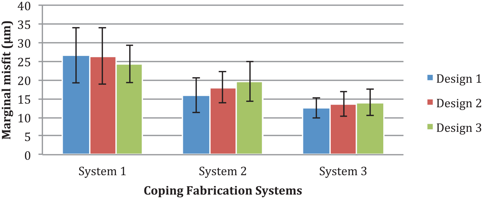
Histograms comparing mean marginal misfit of copings tested.
With regards to finish line types, Design-1 (chamfer) showed a mean marginal misfit of 26.6 ± 7.5 µm, 16 ± 4.7 µm, and 12.49 ± 2.8 µm for System-1, System-2, and System-3 specimens, respectively. Similarly, Design-2 (chamfer with shallow depression) specimens showed marginal openings of 26.4 ± 7.6 µm, 18±4.17 µm, and 13.6±3.34 µm for System-1, System-2, and System-3 specimens, respectively. While Design-3 (chamfer with deep depression) specimens showed mean marginal gaps of 24.3 ± 5 µm, 19.6±5.3 µm, and 14 ±3.61 µm for System-1, System-2, and System-3 specimens, respectively (Table 1). Among the systems tested there was significant difference between finish line design type 1, type 2 and 3 (p < 0.05).
Among specimens fabricated with System-3, marginal misfit for Design-1’ copings were significantly lower than Design-2 and Design-3, respectively (p < 0.05). Among System-2 specimens, Design-1’ copings showed significantly lower marginal misfit compared to copings with Design-2 and Design-3, respectively (p < 0.05). However, among System-1’ specimens, all preparation designs (Design-1, Design-2, and Design-3) showed comparable marginal misfit (p > 0.05) (Table 1).
Discussion
The present study was based on the hypothesis that the marginal accuracy of Y-TZP restorations would significantly differ based on the margin configurations and CAD-CAM system used in their fabrication. Study findings revealed a significant influence of the CAD-CAM system type used and the margin configuration design on the marginal misfit. Therefore, the hypothesis was rejected. Factors including scanner focal lengths, wet and dry milling, measuring misfit methods, and materials used are potentially associated with these study outcomes.
Marginal misfit is defined as the discrepancy or the “gap” between a restoration and the prepared tooth margin11, 12. Holmes et al. defined the absolute marginal discrepancy as “angular combination of the horizontal and vertical error which would reflect the total misfit at that point” 11 . The clinical long-term success of any restorations is dependent on the accurate marginal and internal fit. Accurate fit of restorations is extremely essential to achieve acceptable longevity13, 14. The presence of discrepancies at the crown margin favors the formation of plaque and microleakage, increased dissolution of the cement that can lead to secondary caries, and/or periodontal disease13, 15. According to the literature, marginal fit assessments can be either qualitative (inspection, exploratory probing, and radiographic examination) which is limited by human visual perception of 60 μm, 16 or quantitative including, image magnification medium, a profile projector, and microscope 17 . There are no clear guidelines on determination of a clinically and biologically acceptable marginal and internal fit. The American Dental Association specification 18 states that the luting cement film thickness for a crown restoration should be no more than 25 µm using a type 1 luting agent, or 40 µm with a type II luting agent. However, Øilo and Evje DM suggested that a marginal gap that ranges from 25–40 µm is a clinical goal 19 . Nonetheless, Christensen reported that the clinically detectable marginal discrepancy for subgingival margins is 34–119 µm, and 2–51 µm for supra-gingival margins. He also related, that marginal discrepancies of 39 µm or more in visually accessible surfaces are unacceptable 20 . However, several authors have considered that marginal discrepancies between 100 and 150 µm are clinically acceptable21 –26.
In the present study, mean marginal misfit for copings fabricated using System-1 (Vitablocks® Mark II) and System-2 (CAD/CAM Cerec® inLab) was 25.7 µm and 18.1 µm, respectively. However, previous studies have shown higher misfit values with an average of 43 ± 23 µm, 27 and 53 µm to 66 µm 28 using the same CAD-CAM systems. In addition, copings in System-1 showed significantly higher misfit values compared to System-2 copings. Interestingly, the material and milling machine in these systems were similar; however, the scanning devices were different. System-1 utilized InEos Red Scan; however, a Cerec® AC Connect with BlueCam was employed in System-2 coping fabrication. Therefore, the scanning device appears to be accountable for the significant difference found for marginal gap measurements between copings made in System-1 and System-2. A possible explanation may be derived from the fact that System-1 (InEos Red Scan) has a manual adjustable knob for image focusing on the preparation, meaning that the InEos Red scan needs a larger focal depth distance to scan the die to get an acceptable marginal gap measurement, while the System-2 (Cerec® AC Connect with BlueCam) has an automatic image capture system, an anti-shake function, as well as an extensive depth of field of 14 mm29 –31. These features could have influenced the accuracy of stone model scanning for the two systems. In addition, the parameters for System-1 were optimized by the operators to simulate with other systems as their parameters were fixed according to manufacturers’ instruction. This may have influenced the outcomes of the study.
Interestingly, copings fabricated using System-3 (Zirconia-NobleProcera™ Optical Scanner Noble-Procera™ milled) showed significantly lower marginal misfit among all systems tested, irrespective of the margin design. In contrast to other systems used in the study, the NobleProcera™ Optical Scanner has the “new conoscopic holography;” which has more measurement stability and is less susceptible to external light. It also, can digitalize convex and concave geometries and measure steep slopes up to 85º, and has a focal depth between 8 and 10 mm 32 . These features of advanced comprehensive scanning, in the authors’ opinion, are responsible for the high accuracy of the copings milled using System-3.
In the present study, finish line configuration showed significant affect on the marginal misfit for System-2 and System-3 specimens; however, for System-1 there was no difference observed (Table 1). It was hypothesized that, remarkably, varying the depression area at the coping margins has an effect on their misfit; no significant difference of varying depressions at the finish line was observed in the System-1 specimen. DeHoff and Anusavice, have reported previously that the design of the margin did not affect the ultimate fit of the restoration 33 . A similar study suggested that no significant differences were observed when marginal gaps among metal-ceramic crowns with shoulder, shoulder-bevel, and chamfer finish line were compared 34 . Interestingly, System-2 and System-3 outcomes had a significant difference between finish line design types, which could point to the scanner’s focal depth to detect the depression area at the finish line, and its compensatory mechanism. Among CAD-CAM scanners, it is critical to have the camera stable, with correct angulation and height from the tooth to capture an acceptable image; this suggests that as depression area at the finish line area gets deeper it is challenging for some scanners, such as BlueCam, to scan outside of their range30, 31, 35. By contrast, the NobleProcera™ Optical Scanner has increased accuracy with higher focal depth and ability to digitize complex shapes 32 . It exhibited minimum influence of margin design on the marginal misfit, with mean values ranging from 12 to 16 µm. Moreover, it is important to mention that the Procera CAD/CAM system designs and mills a die that is 15–20% larger than the original 32 . However, Cerec inLab compensates for the sintering by machining, which enlarges the work by 25–30%35, 36. This may have an impact on the misfit discrepancies among the study groups. Furthermore, it is suggested that the cutting efficiency, sequence, and duration of use of burs can influence the properties of ceramics including its surface37 –39. The burs were continuously changed on the manufacturers’ recommendations, which differed between systems. This, possibly, affected the outcomes of coping misfit.
The marginal misfits were significantly different among the CAD-CAM systems tested; however, these were well within the clinically acceptable limits. Furthermore, based on the misfit findings, System-3 copings can be recommended clinically over other systems. These outcomes should be considered in light of the facts that in-vitro marginal assessments are lower compared to clinical marginal opening. In addition, methodological limitations such as scanning sprayed stone dies, no use of cement, extra oral scanning, and circular dies with circumferential uniform margins prepared on plastic teeth may have influenced the outcomes of the present study.
Conclusion
The CAD-CAM manufactured Y-TZP’ copings exhibited a marginal gap ranging from 12.49 to 26.6 µm. The CAD-CAM fabrication system was a significant factor influencing the marginal misfit of Y-TZP’ copings. Margin design exhibited system dependent influence on the marginal misfit. The NobleProcera Optical Scanner–Noble Procera™ milling machine–Procera zirconia copings exhibited significantly lower marginal misfit compared to other systems. Marginal misfit observed for all systems were within clinically acceptable parameters.
Footnotes
Author Contributions
KAA, FV and TA: data collection; study design; manuscript writing; and final manuscript approval. AM, AA and MSB: data collection; study design; manuscript drafting; data analysis; and manuscript approval. AAh, SA and TA: data collection; manuscript approval; and data interpretation. KAH, LA and HK: data collection; writing; revision; editing; and final manuscript approval.
Authors Note
Abdulaziz AlHelal’s is now affiliated to Department of Prosthetic Dental Sciences, College of Dentistry, King Saud University, Research Chair for Biological Research in Dental Health, Riyadh, Saudi Arabia.
Hiba Alshehri is now affiliated to Department of General Dentistry, College of Dentistry, King Abdulaziz University, Jeddah, Saudi Arabia.
Declaration of Conflicting Interests
The authors declared no potential conflicts of interest with respect to the research, authorship, and/or publication of this article.
Funding
The authors disclosed receipt of the following financial support for the research, authorship, and/or publication of this article: The authors are grateful to the Deanship of Scientific Research, King Saud University for funding through Vice Deanship of Scientific Research Chairs, Research Chair for Biological Research in Dental Health.
Guarantor
Tariq Abduljabbar.