
Abstract
Biological gradients profoundly influence many cellular activities, such as adhesion, migration, and differentiation, which are the key to biological processes, such as inflammation, remodeling, and tissue regeneration. Thus, engineered structures containing bioinspired gradients can not only support a better understanding of these phenomena, but also guide and improve the current limits of regenerative medicine. In this review, we outline the challenges behind the engineering of devices containing chemical-physical and biomolecular gradients, classifying them according to gradient-making methods and the finalities of the systems. Different manufacturing processes can generate gradients in either in-vitro systems or scaffolds, which are suitable tools for the study of cellular behavior and for regenerative medicine; within these, rapid prototyping techniques may have a huge impact on the controlled production of gradients. The parallel need to develop characterization techniques is addressed, underlining advantages and weaknesses in the analysis of both chemical and physical gradients.
Keywords
Introduction
Physicochemical gradients form the basis of many biological processes, either physiological or pathological, such as angiogenesis 1 , inflammation, 2 and cancer evolution. 3 The gradient of the vascular endothelial growth factor-A stimulates vascularization by guiding filopodia of endothelial cells toward poorly oxygenated areas. 4 Coupled with a gradient of oxygen concentration, this mechanism may also lead cancers to progression and metastasis. 3 Moreover, variation in chemokine concentration is one of the first triggers of neutrophil migration during wound repair. 2
Among the tissues of the human body, bone, cartilage, skin, muscles, myocardium, blood vessels, and nerves display gradients, i.e. variable physicochemical and mechanical properties, within their architectures.5–10 In each of these tissues, gradual variations of the microscopic structures are translated, at the macroscopic level, into anisotropy.
When injuries occur, traditional therapies are unable to recreate the physiological arrangements.11, 12 To bypass this limit, regenerative medicine and tissue engineering aim to develop highly specific devices designed to activate the natural regenerative capability of the tissue.13–15 In this review, we divide such devices into scaffolds—which aim to provide cells with a 3D environment, temporarily supporting regenerative physiological mechanisms—and constructs—scaffolds combined with cells prior to implantation. In their turn, substrates include 2D structures, onto which cells are seeded.
Tissue engineering has turned toward the design of anisotropic devices,16, 17 not only to achieve the complex and difficult goals of clinical therapies, but also to engineer tissues for advanced in-vitro screening systems.18, 19 Not only do screening systems take advantage of this emerging field by testing therapies in more realistic scenarios, but they can also give feedback and ideas about how to fabricate and improve anisotropic devices.18, 19 In this latter case, the activities of biological systems, such as cells and bacteria, are studied as a function of pore size and distribution, mesh size, chemical composition, and concentrations, as well as mechanical properties that gradually change in different spatial locations within the same system, as, for example, in substrates that exhibit hydrophilic-to-hydrophobic or smoother-to-rougher gradients. 20 The presence of a gradient confers to each point of the substrate a specific value of the varying quantity, allowing analysis of the effect of each variable over a specific phenomenon, such as cell adhesion, spreading, morphology, or differentiation. This offers a great advantage to both interfaced tissue engineering and drug screening, as the effect of different variables on a phenomenon is analyzed in a single experimental set-up rather than in a series of experiments at different conditions. 21
Regardless of its application, a gradient is mathematically defined as the vector that has the partial derivatives of a variable as components. Therefore, the gradient of a scalar quantity is used to describe the variation of that quantity along a spatial direction. Hence, gradients can be classified according to the variant quantity, 22 i.e. chemical and physical gradients, and depending on how this varies within the space: linear, radial, orthogonal, exponential, and other non-linear shapes, e.g. sigmoidal and orthogonal (Figure 1). 23
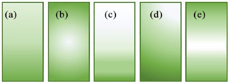
Classification of gradients according to their arrangements: (a) linear; (b) radial; (c) exponential; (d) orthogonal; (e) sigmoidal gradients, as representative of non-linear shape. Figure adapted from Smith Callahan. 23
Until now, chemical gradients have been obtained by varying the spatial concentration of proteins, organosilanes, or alkanethiols, on the scaffold surface or volume, while physical gradients consist of changes of mechanical, topological, and morphological characteristics, such as stiffness, thickness, porosity, or roughness.21–24
Methods to generate graded substrates
Gradients are fundamental in effectively reproducing the anisotropy of many human tissues. Moreover, they are the basis of many biological phenomena that influence cellular and bacterial responses.21, 25, 26 Many methods to engineer devices that exhibit chemical or physical gradients to study cellular behavior are herein reported. These include semi-immersion of substrates, the use of diffusion systems, selective irradiation of photoreactive polymers, variation of the substrate thickness, and the use of microfluidic devices.
Semi-immersion
Semi-immersion involves soaking a substrate, which has been previously subjected to chemical surface treatment, in a buffer solution containing reagents or crosslinking agents (Figure 2(a)). The linear diffusion of the solution leads to a gradual chemical change on the substrate surface and, therefore, the formation of a chemical or physical gradient. In this way, it is possible to generate wettability gradients on silica substrates, resulting in hydrophobic-to-hydrophilic gradients.27–29 Another example is the immersion of a gold-coated silicon substrate in alkanethiol solution, using a computer-driven gripper, to produce a hydrophobic gradient. 28 This method provides a useful tool to study cell adhesion and migration, since cell response is well known to be strongly dependent on the wettability of a substrate.20, 29 Tomlinson and Genzer also produced a linear molecular weight gradient of poly-methyl methacrylate on silica surface, with the aim of developing a simplified method for precise and tunable polymeric thin-film formation. 30 In this technique, a silica substrate coated with a polymerization initiator is semi-immersed in a solution of the monomer (methyl methacrylate). The reaction kinetic is controlled by adjusting the level of the liquid (i.e. the polymerization duration), thus forming polymer chains with a length that is proportional to the time for which the solid–liquid interface is maintained. 30
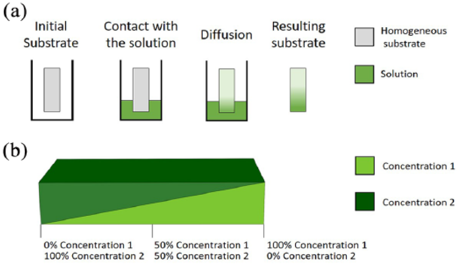
(a) Semi-immersion procedure. The substrate is partially immersed in a solution of the desired chemical compounds. The diffusion of molecules from the bath to the substrate surface results in a linear physicochemical gradient. (b) After two crosslinking steps, a gradient of elastic properties results from a variable ratio of the chemical components forming the substrates.
Diffusion
Diffusion is another technique employed to generate gradients; this utilizes either two solutions with different concentrations of the same chemical or two solutions with different compositions. The solutions are generally deposited on two distinct points of a mold or on an already formed substrate. There, they act as donor and receptor for the diffusion of the compounds in the interconnected space. Many well-established systems, such as Transwell® inserts, 31 the Zigmond chamber, 32 and the Dunn chamber 33 belong to this category. Moreover, some more recent microfluidic systems can also be included in this category, such as the system designed by Diao and colleagues for the study of bacterial chemotaxis, which consists of a nitrocellulose membrane with three different longitudinal parallel spaces. 34 The external compartments contain the solution with the chemotactic compound and the reservoir. The chemotactic agent diffuses through the nitrocellulose membrane from the solution container to the reservoir and crosses the interposed empty space, where the linear concentration gradient is generated.35, 36
Although diffusion systems allow the efficient generation of chemical gradients, 37 they can also be used to design mechanical gradients. A stiffness gradient was created by linear variation in a space of bis-acrylamide concentration exposed to homogeneous ultraviolet irradiation. In this way, the Young modulus of the resulting polyacrylamide layer increased linearly, from the point where the higher concentration of bis-acrylamide was placed to the opposite end. 38 Heat diffusion can also be exploited for physical gradient generation. One side of a silicon wafer coated with polystyrene nanoparticles was heated at 130 °C while the other was maintained at room temperature, resulting in a directional-oriented melting of the polystyrene particles. Hence, a linear roughness gradient was obtained on the silica surface, as demonstrated by atomic force microscopy and wettability analysis. 39
Compositional topography
By tuning the thickness, it is possible to obtain chemical concentration gradients and gradients of mechanical properties (e.g. Young modulus). A linear stiffness gradient was created to study durotaxis (i.e. cell motion induced by a rigidity gradient) of human adipose-derived stem cells. 40 A double step polyacrylamide crosslinking process was used, each step starting with two different concentrations (concentrations 1 and 2) and producing two superimposed triangular hydrogels (Figure 2(b)). The hydrogel produced in this way has a linear polyacrylamide gradient ranging from 100% concentration 1 to 100% concentration 2. 40
The thermoresponsive behavior of poly N-isopropylacrylamide (PNIPAM) has been exploited to form a thick sigmoidal gradient. 41 A constant layer of PNIPAM with the addition of spatially variable concentrations of hydrophobic and hydrophilic co-monomers defined different low critical solution temperatures in different points of the system. In this way, by raising the temperature to a certain prefixed value, only the portions of the polymer at temperatures above the low critical solution temperature collapsed, while the others maintained their swollen state. This method allows both the thickness of the layer and the profile of the gradient to be adjusted. The ratio between hydrophilic and hydrophobic co-monomers in the substrate determines how, at a specific substrate point, the PNIPAM layer is shortened. In the same way, the spatial disposition of these groups defines the thickness gradient profile. The procedure is particularly complex because it involves the generation of a chemical gradient of hydrophobic and hydrophilic groups before creating a thermal stimulus. A gradient of Young modulus was obtained in collagen/poly-caprolactone copolymers by simply varying the amount of collagen or poly-caprolactone. Specifically, poly-caprolactone was used as a rigid substrate where the more elastic collagen was deposited. A higher predominance of collagen led to lower stiffness of the composite, and vice versa. 42 Since collagen is well-suited for cell cultures, human mesenchymal stem cells were not only seeded on the surface of the composite, but also encapsulated in the collagenous layer to compare 2D or 3D culture conditions in terms of cell spreading and migration as well as to study the influence of the stiffness gradient. However, the limit of this study is the difficulty in distinguishing the effect on cells, owing to the presence of a gradient, on the one hand, and the different 2D and 3D settings, on the other hand.
Selective irradiation
Selective irradiation has also been used to generate physical or chemical gradients. Selective irradiation produces inhomogeneous crosslinking by partial, dynamic, or multiform irradiation of previously homogeneous photoreactive substrates. Usually, the substrate is made of polyacrylamide/bis-acrylamide solution and is irradiated with ultraviolet rays (Figure 3). The gradient is formed by varying the time of substrate exposition to the ultraviolet source, by means of an opaque mask. 43 By maintaining a constant polyacrylamide thickness, it is possible to modify the mechanical and elastic properties by adjusting the movement speed of the opaque mask. This method is appreciably simple and potentially capable of generating any shape of gradient (linear, exponential, sigmoidal, orthogonal, etc.), as it can be modified and adapted to specific work requirements and easy-to-control parameters, i.e. the shape and speed of the mask movement. Wong et al., 44 for example, modified the mask by increasing its degree of opacity from the center to the edges, generating a radial gradient of crosslinking. In another strategy, a mask with one or two holes was interposed between the light source and the monomeric solution. This strategy reduces the area of light incidence45, 46 and improves the control of the light path on the substrate, the shape of the gradient, and also its location on the substrate. Since cell adhesion, spreading, and differentiation depend on the substrate stiffness, 47 these highly adjustable physical gradients can be used as a specific tool to guide cell behavior. Moreover, this method would potentially allow the design of substrates with multiple gradients, each with different and highly specific paths. However, it has the constraint of a limited choice of materials, which have the strict requirement of being photoreactive, such as polyacrylamide and gelatin.
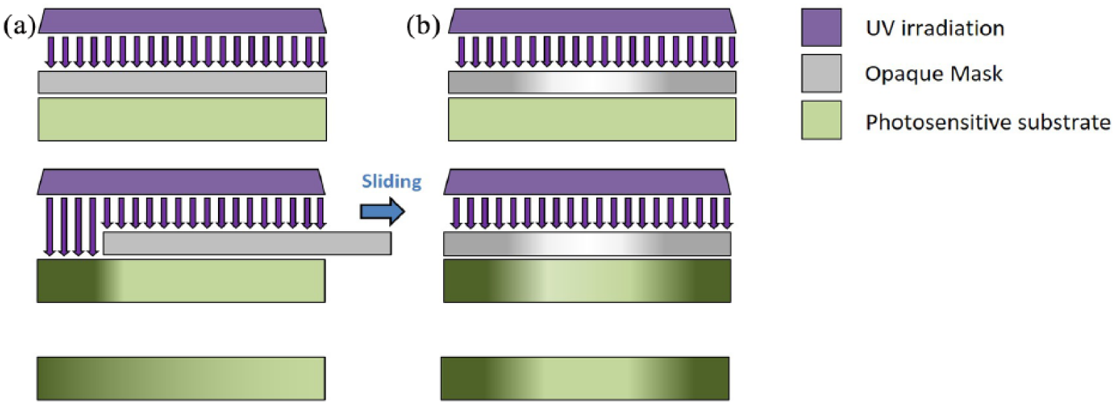
Selective irradiation method to induce linear or radial gradients on a photosensitive substrate. Ultraviolet (UV) irradiation is selectively filtered by a mask, which is either completely opaque (a) or has a designed distribution of opacity (b). The movement of the mask or the selective irradiation induces a controlled modification of the substrate, which results in a physical or chemical gradient.
Microfluidic devices
Advanced techniques, such as rapid prototyping and soft lithography have made it possible to accurately manufacture devices with complex geometries. Microfluidic systems form just one application of these techniques. 48 In the field of fluid dynamics, the use of channels with small diameters (1–300 µm) produces a low-Reynolds-number flow in the microdevices, entailing a solid theoretical knowledge of the shear stress and fluid velocity profile. 49 In this way, a specific fluid dynamic pattern can be formed in the tubes, with the aim of producing the desired gradient shape. For example, liquid flow in the microchannels can be controlled to define the gradient of oxygen concentration in a bacteria culture chamber for biofilm production and analysis. 50 Jeon and co-workers created a device capable of generating multiple gradients by designing a system with three chemical sources from which a series of interconnected channels branched off into a Christmas-tree-like structure. 51 By varying the number of chemical species and fluid dynamic parameters (e.g. the velocity of the fluid), it is possible to change the shape of the gradient in the output channel. 52 This technology requires a deep knowledge of fluid dynamics and, experimentally, the achievement of the stationary regime. However, it allows the design of very versatile and precise gradient generators. This method has been adopted to engineer linear concentration gradients of polyacrylamide and bis-acrylamide for studying the migration of vascular smooth muscle cells. After ultraviolet treatment, Hartman et al. could obtain a substrate with variable stiffness suitable for the application. 53 By combining several different chemicals and simultaneously controlling their flows, the microfluidic approach can generate orthogonal gradients (Figure 1(d)), which are particularly difficult to obtain through other methods. An example is the microfluidic system of Hu et al., 54 which is composed of three layers of channels in a chessboard-like organization: channels are vertically connected by reservoirs in which the solutions are collected. Each of these reservoirs contains a different quantity of two chemical components, generating an orthogonal concentration gradient. The microfluidic dynamic system is particularly useful for efficient combinatorial drug screening. By using minimal amounts of volume, microfluidic systems combine significant savings in expensive reagents, such as antibiotics and cell culture media, with a user-friendly and highly customizable set-up. 55
Production of graded scaffolds
Scaffolds exhibiting gradients are mainly generated by either multi-layered or intrinsic-gradient approaches (Figure 4).
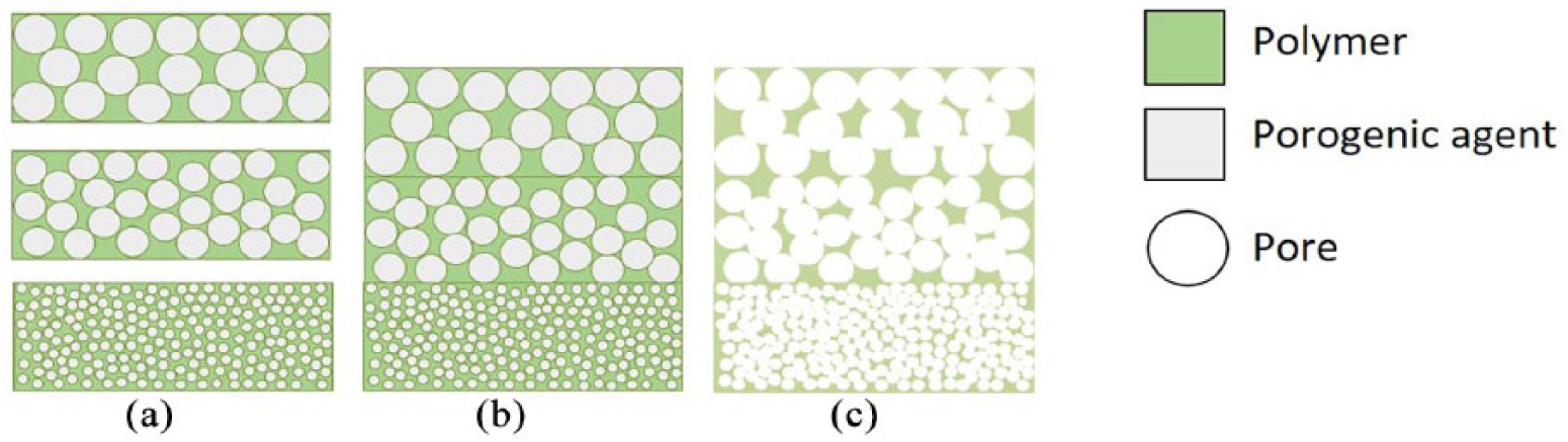
Multi-layered approach combined with solvent casting or salt leaching to produce graded scaffolds: (a) homogeneous scaffolds displaying different chemical or physical properties; (b) assembly by different methods (e.g. compression molding); (c) porogen leaching by successive washes, performed either by water or a suitable solvent, to generate void spaces with variable sizes and dimensions within the scaffolds.
The multi-layered approach relies on several homogeneous scaffolds designed with different chemical or physical properties, which are then further assembled (Figure 4(a)). This leads to an in-situ gradient, usually characterized by discontinuous and abrupt passages between layers. The intrinsic-gradient approach (Figure 4(b) and (c)), in its turn, takes advantage of specific manufacturing processes to engineer scaffolds with intrinsic chemical or physical gradients. In this case, the gradient is usually continuous, with smooth variation of the chemical or physical properties within the system. Both methods are suitable for the fabrication of scaffolds for the regeneration of a single tissue (bone, cartilage, skin, tendons, nerves, etc.) or for interface tissue engineering (cartilage-to-bone and tendon-to-bone, among others).
Multi-layered approach
Solvent casting or particulate leaching
Particulate leaching is a classic technique employed to develop homogeneous porous scaffolds with controlled porosity, yet it can be easily modified to generate gradients.56, 57 In two studies, graded polylactic acid/polyethylene glycol and poly-caprolactone/polyethylene glycol composites have been produced using a saline porogen (NaCl) with varying granularity to form three different porosity polymer matrices. The three layers were combined by compression molding and washed with distilled water to build high-porosity graded scaffolds.58, 59 In both studies, 70% porosity was obtained, as well as good integration of the three layers. Compression tests showed anisotropic behavior and mechanical properties that were intermediate between those of controls with maximum and minimum porosity. In addition, breakdown tests demonstrated scaffold collapses, starting from the maximum pore-sized layers, through to those with minimum size, following a clear gradient of mechanical performance.
The main advantages of this method are the simplicity of the protocol, the possibility of designing scaffolds with different geometries by changing the mold architecture, and the direct regulation of both porosity and pore size, simply by varying the concentration and the granularity of the porogen. 60
Thermopressing ultra-high molecular weight polyethylene (UHMWPE) combined with a NaCl solvent casting or particulate leaching process was used to generate radial porosity gradients. 61 In this hybrid method, high-temperature compression of UHMWPE powder and NaCl (the porous core) were inserted in a pure UHMWPE cylindrical mold (the external shell) and washed with subcritical water for salt removal. Anisotropic and mechanically performant, the scaffolds displayed elastic properties similar to those of trabecular bone tissue with a Young modulus of 0.7 GPa, and high porosity (about 70%) with variable pore size (80–700 µm). On in-vivo implantation in mice, the graded scaffolds generated guided tissue granulation and vascularization. However, this methodology presents two main limitations: the necessity of using thermoresistant materials and the impossibility of generating low-porosity (<30%) graded scaffolds suitable for promoting osteogenesis. 62 A thermoresistant material is required, since it must endure high-temperature and high-compression conditions, while low porosity cannot be obtained, since the washing of small salts is significantly limited by the presence of the surrounding polymeric shell. 61
Lyophilization
By employing lyophilization, scaffolds with gradients bearing any shape or dimension required can be generated, using different shaped molds. For example, an internal cylindrical heart shape or a hollow cylindrical shell shape could be approximately formed during the development of scaffolds with a hydroxyapatite gradient for bone tissue regeneration.63, 64 In the first case, after the lyophilization process of the core polymer, a second solution with a different concentration of hydroxyapatite was poured around the already formed central sponge, ensuring that no bubbles were generated, which could damage the integration between the communicating surfaces of the layers. 64 In the second case, a hollow cylinder previously obtained through lyophilization served as an external shell of a successive structure that consisted of a polymer solution with a higher concentration of ceramic powder (Figure 5). 63 During the second subsequent lyophilization, a radial gradient scaffold of hydroxyapatite was formed in both methods. As demonstrated by Teng et al., this method is particularly useful in controlling drug delivery kinetics. Adding external layers of chitosan or hydroxyapatite to composite scaffolds greatly reduces the burst effect in drug delivery and extends the time over which the drug is released. Indeed, in a drug delivery model (of tetracycline hydrochloride), cumulative release reached 60% after 10 days using the graded structure and after only 1 day using homogeneous controls. 64
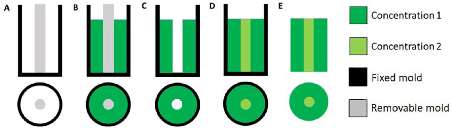
Gradient production. A first polymeric solution is poured in a double cylindrical holder (a, b) and then lyophilized. Then the internal cylinder is removed (c) and the void is filled with a second solution (d). After a second freeze-drying step, a radial gradient, made up of polymeric layers with different properties, is achieved (e).
Lyophilization is also exploited to generate multi-layered scaffolds for interface tissue engineering. Usually, a number of matrices of collagen are loaded with increasing hydroxyapatite powder concentration, thus mimicking both cartilaginous (pure collagen matrix) and bone (high hydroxyapatite concentration) structures. Each layer is lyophilized separately, and the layers are then assembled and dried together for the adhesion of the layers at the interface.65, 66 This method is versatile and has the potential of accurately modeling each layer of the interface between cartilage or tendon and bone, promoting the proliferation of fibroblasts, chondrocytes, and osteoblasts. However, no mechanical studies have been conducted to verify the adhesion between layers, which would be crucial for in-vivo applications.
Using this method, a “sandwiched” tri-layered scaffold with different concentrations of collagen and hydroxyproline has been designed, and its regenerative potential when applied to dermal injuries has been evaluated. 67 The graded scaffold clearly evidenced the benefit of gradients for cell proliferation, tissue granulation, healing velocity, and integration with the host tissue after in-vivo implantation in mice. 67 After 7 days, wounds healed by about 75% and 95% in homogeneous and “sandwiched” scaffolds, respectively. Despite these promising macroscopic results, the mechanisms behind those improvements have not been fully described; and further studies are required to gain deeper knowledge of the healing dynamics.
Intrinsic-gradient approach
Centrifugation
One of the simplest methods of generating continuous gradient scaffolds is centrifugation. Since the centrifugal force depends on the distance from the rotation axis, particles in the distal part of the container will experience a greater force than proximal ones. This principle has been exploited, for example, to create a porosity gradient in a poly-caprolactone scaffold. 68 First, poly-caprolactone was homogeneously suspended in a solution of Pluronic F127 and then centrifuged at high frequency. During centrifugation, the poly-caprolactone arranges itself in fibril-like structures that become thicker toward the base of the centrifuge. After dialyzing the Pluronic F127, fibril bonding (50 °C) and subsequent freezing, a poly-caprolactone solid scaffold with a porosity gradient was obtained. Smaller pores were observed on thicker poly-caprolactone fibers, and vice versa. 69 The same method was used by Marrella et al. 70 to create both a porosity gradient within poly-caprolactone and collagen scaffolds and a chemical gradient of hydroxyapatite concentration. In this study, a mathematical sedimentation model was validated to effectively predict pore distribution within the poly-caprolactone and collagen scaffolds as a function of different centrifugation parameters, such as rotation radius, radial velocity, frequency, and centrifugal acceleration. In both these studies, the authors concluded that larger pores lead to effective improvement of cell adhesion and migration, glycosaminoglycan synthesis, and chondrogenic marker expression.69, 70
Despite the discussed advantages, centrifugation allows only a linear gradient to be produced; no other conformations can be obtained, since the sedimentation in the centrifuge results in a linear physicochemical gradient. However, the generation of non-linear gradients appears to be crucial for interface tissue engineering.
Plastic compression
During compression conditions, the polymer chains of homogeneous polymeric scaffolds can be rearranged. Plastic compression can be used in both confined and non-confined set-ups (Figure 6). In the first case, the scaffold is placed in a container with a permeable membrane that allows the flow of the incompressible liquids out of the holder without the formation of vortexes that might affect the rearrangement of collagen chains. 71 Conversely, in the non-confined set-up, the absence of a holder to restrain the polymeric matrix results in difficult control of the samples within rigid boundaries, making the direct application of loads impossible. For these reasons, the scaffold sheet is first rolled, and subsequently subjected to compression by a piston.72, 73 After compression, the randomly oriented polymeric fibers redistribute within the structure, aligning themselves in the transverse direction of the loading axis. The fibers in the upper part of the mold are subjected to an instantaneous load and, moving toward each other, form increasingly denser layers of parallel polymer fibers. Conversely, the polymeric chains in the lower volume of the holder feel the resistance of the upper denser layers. In that region, no thickening is observed, and the degree of random orientation of the fibers is maintained. In this way, a molecular orientation gradient is generated, where the polymeric fibers at the top of the scaffold are homogeneously distributed and gradually reorganized in a dense and parallel disposition. 71 By varying the geometry of the container (cylindrical, cuneiform, etc.), it is possible to subject the polymers to different densification processes. Since larger matrix volumes will lead to a greater thickening, 74 a simple geometric modification allows the formation of a gradient of polymer concentration with subsequent change of the mechanical properties. In particular, graded collagen scaffolds with two degrees of compression (30% and 90% of maximum strain) can be produced. Huge differences in the Young modulus, about 20-fold, were observed between homogeneous scaffolds and the portions of the graded scaffolds with higher concentrations of collagen (E = 4.5, 92.9, and 94.4 kPa for homogeneous scaffolds, and graded scaffolds subjected to 30 and 90% strain, respectively). 75
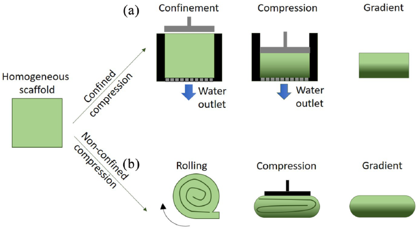
Confined (a) or non-confined (b) plastic compression can be exploited to induce gradients in the porosity and mechanical properties of elastic polymers. The homogeneous scaffold is compressed, in a molder or after rolling, with constant or variable load to induce alterations in the polymeric network and a macroscopic plastic deformation.
Freeze-casting
Freeze-casting requires three fundamental components: powder, usually ceramic; a solvent; and a polymeric reinforcing agent. The slurry, composed of the three ingredients, is subjected to a decreasing temperature ramp until freezing and then to low-pressure vacuum drying. 76 The frozen phase is kept under a temperature gradient, which is frozen at one side of the slurry, while thermally insulated or at room temperature at the other (Figure 7). In this way, nucleated ice crystals grow along the temperature gradient profile, forming highly anisotropic ice structures. At the same time, the front of crystalline growth imposes the redistribution of the powder suspension within the slurry on the opposite side of the ice, generating a chemical gradient of the ceramic component. The minimum concentration of the ceramic is observed close to the frozen side and the maximum at the opposite side. Once the freezing phase is completed, the ice crystals are lyophilized at low pressure or under vacuum to generate a porosity gradient in the reinforcing agent matrix, which is usually sintered to gain mechanical stability. 77 This method, although simple, requires accurate evaluation of many parameters, such as shape, intensity, and duration of the temperature gradient, as well as the type of powder and reinforcing agent.
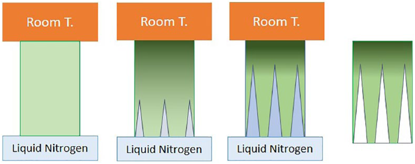
Controlled crystallization in a substrate is achieved by connecting one edge to a liquid nitrogen reservoir and the other to a heat generator or maintaining it at room temperature. In this way, nuclei of ice grow in an anisotropic geometry, guiding the chemical compounds in the polymeric matrix on the opposite area of the ice propagation. After the designed time, the substrate is lyophilized, thus sublimating the crystals and the gradient of porosity and chemicals is obtained.
Although different ceramics (i.e. alumina, zirconia, titanium dioxide, hydroxyapatite)78–80 and bioglasses81, 82 are mainly used in freeze-casting, metals (such as ferritic stainless steel 83 ) and composite materials77, 84 can also be selected for this process. Different concentrations of hydroxyapatite and poly(lactic-co-glycolic acid) microparticles within a gelatin solution have been combined into a scaffold with tunable degrading and swelling properties, as well as strong mechanical behavior defined by the hydroxyapatite concentration. 85
The freeze-casting method modified by Bai et al. 86 allows the generation of radial gradients, exploiting the resulting capillary effect to enhance cell migration in the deepest portion of the scaffold. A slurry composed of distilled water, hydroxyapatite, and a water-soluble polymer mixture (polyethylene glycol, poly(2-ethyl-2-oxazoline), and Aquazol) is poured into a cylindrical container with a copper rod in the middle, which is then connected to a liquid nitrogen reservoir. In this way, the freezing front moves radially outward, forming a channel gradient structure with the hydroxyapatite arranged in radial planes, parallel to the ice front. Interestingly, when the bottom part of the scaffold is partially immersed in a cell culture medium loaded with mesenchymal stem cells, cells migrate spontaneously from the solution to the scaffold, penetrating by capillarity. 86 By replacing the ceramic powder with a metal powder of Ti6Al4V, a gradient of porosity from 40% to 78% can be obtained, exhibiting a pore size distribution in a range of 40–155 µm and mechanical anisotropy comparable to bone tissue. Although the inverse relationship between pore size and mechanical properties was confirmed, temperature influence was not detected. 87
Although the three components are usually combined, it is also possible to exploit the freeze-casting technique without the presence of a powder, which results in a physical but not a chemical gradient. An anisotropic frozen alginate scaffold was produced by gradual cooling of the polymer solution, lyophilization, and final immersion in a solution with a high concentration of CaCl2 for structural stabilization. 88 No mechanical tests were carried out, but morphological analyses were conducted to evaluate the effect of temperature on pore characteristics. In particular, it was observed that the initial exposure temperature and the duration of the freezing influenced pore size (from 10–65 µm to 50–141 µm), while the temperature gradient defined the pore shape.
Graded structures by rapid prototyping
Developed as an alternative to traditional techniques, rapid prototyping includes automatic deposition of layers, aiming to reproduce the geometry of a computer-aided design model.89, 90 Such parameters as deposition velocity and amount or distribution of the material can be easily modified to vary mechanical properties and other factors, such as pore distribution and size. 91 Alternatively, different materials can be used during printing to engineer a single structure with controlled positioning of each material according to the aim of the design.
Selective laser sintering
One of most common rapid prototyping techniques is selective laser sintering, which exploits a high-power laser source to selectively melt polymer particles. By alternating the melting and deposition of new polymeric powder, a multi-layered scaffold with a complex geometry can be produced. Commonly used to produce homogeneous scaffolds, this method can be easily modified to obtain both chemical and porosity gradients. For example, differently sized poly(d-lactic acid) microspheres (ranging from 75 to 425 µm) coated with titanium were sintered to control porous distribution, as well as titanium concentration and deposition. By varying the distribution and the dimension of the poly(d-lactic acid) particles, the desired shape and intensity of the gradient was imposed. This method is particularly advantageous because it generates highly porous scaffolds with interconnected pores, which could improve osteoblast adhesion, matrix production, and cell migration. 92 Moreover, the solvent-free set-up allows reproducibility, simplicity, and cost-effectiveness. However, the high temperature necessary for the selective laser sintering process limits the material choice.
Fused deposition modeling
Fused deposition modeling is a well-established technology for producing scaffolds made of thermoplastic materials, such as poly-caprolactone, polylactic acid, poly(lactic-co-glycolic acid), and polyethylene glycol, and is extraordinarily adaptable in generating gradients. One of the main limitations of this technique, however, is the creation discontinuous gradients. This rapid prototyping technique is not a multi-layer method, since the gradient—although discontinuous—is generated in a single system composed of overlapped fibers and not by multiple structures with different properties, successively assembled together.
There are two main methods for generating physical gradients in fused deposition modeling structures. The first involves printing fibers with constant diameters in layers with 0°–90° orientation, while changing their relative line spacing. Poly(ethylene oxide terephthalate) and poly(ethylene oxide terephthalate) scaffolds, composed of four zones with different fiber spacings (500, 700, 900, and 1100 µm) have shown superior ability to guide differentiation of human mesenchymal stromal cells into chondrocytes, compared with homogenously porous scaffolds and, consequently, to represent a suitable strategy for cartilage regeneration. 93 A similar method has been adopted to produce scaffolds with radial porous gradients in a bioinspired strategy for bone tissue engineering. 94 A gradient was obtained by varying the distance of the poly(ethylene oxide terephthalate) and poly(ethylene oxide terephthalate) fibers. Each layer was produced in three concentric circular crowns with fiber distances of 500, 750, and 1000 µm, moving toward the middle, thus resulting in a radial gradient with increased porosity. The presence of gradient scaffolds was beneficial for cellular activity, with higher cell density and higher osteogenic differentiation of human mesenchymal stem cells in areas with larger pores. Scaffolds made by imposing a fiber distance of 750 µm at the top and bottom ends and 100 µm in the middle displayed strong mechanical anisotropy. Indeed, the overall compressive behavior was between those of homogeneous control scaffolds with 750 and 100 µm fiber distance. Moreover, an improvement in cell viability was observed. Remarkably, since the gradual decrease of fiber distances from the ends to the core was imposed to be 50 µm/layer, the gradient is a quasi-, but not strictly, continuous porosity gradient, 95 partially overcoming the main limit of fused deposition modeling as a gradient-maker technique.
The second method for generating gradients by using fused deposition modeling involves changing the orientation of the fibers layer-by-layer, thus controlling the interposed empty space, leading to the generation of a porosity gradient. By varying the orientation of the fibers by 15, 30, 45, and 90° every six layers, a gradient of pore geometry was generated in poly-caprolactone scaffolds at a fixed porosity (73%). Interestingly, the variation of the pore geometry not only determined the mechanical anisotropy of the scaffold, but also a gradient of oxygen concentration, which guided a greater chondrogenic differentiation where the fibers were orthogonal to each other, and osteoblastic differentiation where the angle was 15°. 96
Fused deposition modeling can be coupled with bioprinting (described next) to manufacture graded constructs in rapid and automatic procedures. For example, a double extrusion system that selectively deposited polyurethane or poly-caprolactone generated a stiffness gradient within the scaffold, aimed to reproduce the muscle-to-tendon interface. Afterwards, bioinks (hyaluronic acid, fibrinogen, and gelatin) loaded with C2L2 or 3T3 were bioprinted on the polyurethane/poly-caprolactone composite scaffolds, offering selective seeding of the cellular component on the final graded constructs. 97
Bioprinting
Bioprinting suits a wide range of biocompatible materials of both natural and synthetic origin, including collagen, gelatin, alginate, pectin, hyaluronic acid, soy protein, fibrinogen, chitosan, polyethylene glycol, PNIPAM, polyphosphazenes, and composites. Unfortunately, even if the choice of materials is vast, the requirements that make the polymer “printable” are strict. 98 Indeed, bioinks must have the correct viscoelastic properties that would allow the flow of the material inside the needle (i.e. a shear thinning behavior) and, after extrusion, a sufficiently stable fiber should be attained to mechanically support the multi-layer structure.99, 100 However, when printability is achieved, bioprinting allows for the design of an almost unlimited variety of gradients.
In a patient-specific strategy, bioprinting was combined with imaging techniques to develop scaffolds exhibiting specific fiber orientations. Briefly, using computer tomography or magnetic resonance imaging, a scan of the target bone structure was acquired, then converted into printing geometry via computer-aided design. 101 A radial porosity gradient was then formed, in this case, by the alternating superimposition of zigzag layers and spiral layers of crosslinked alginate. With this procedure, it is possible to combine anatomical precision with a porosity gradient, although considerable computational effort is required.
Biochemical gradients are more complex to achieve with bioprinting. Indeed, changes in the chemical composition of printed scaffolds imply the need to use different bioinks during the printing process.
Using a bioprinter that can load a number of bioinks allows different materials to be printed independently, in sequential order and correct position. At the end of the process, a scaffold made with different compounds arranged in specific locations can be obtained. Four bioinks were printed in sequences to reproduce the extracellular matrix and vessel structures: polydimethylsiloxane, methacryloyl-gelatin, Pluronic F127 (a triblock poloxamer), and methacryloyl-gelatin loaded with cells. This architecture induced long-term cell viability and growth comparable to those of a homogeneous scaffold. 102 Bioprinted scaffolds formed from three different concentrations of gelatin and fibrinogen showed greater osteogenic differentiation of human amniotic fluid stem cells when applied as in-vitro constructs, and induced vascularization or new tissue formation when implanted in mice. 103 However, the time necessary to complete the printing is severely prolonged by the numerous switch times (near 20 s each one) of the different nozzles needed for alternating the deposition of different materials. Moreover, the inks must usually be crosslinked after extrusion, limiting the choice of suitable biocompatible materials.
Simultaneous printing of different bioinks leads to subsequent improvement of the sequential-extrusion approach. In this case, each bioink reservoir is connected to the extruder by vessels or similar microfluidic devices, where the different bioinks are mixed together in the correct proportion before the printing process. By regulating the number and quantity of bioinks flowing into the extruder, it is possible to select the composition of the printed filament that will be continuously deposited, avoiding the process interruption. For example, methacryloyl-gelatin and alginate solutions were selectively mixed in a Y-shaped microdevice, printed, and then crosslinked through a coaxial needle. 104 This concept was further expanded by using seven bioinks stored in an equal number of reservoirs. 105 Seven peristaltic pumps regulated the number and the flow of the bioinks during printing in continuous extrusion mode, allowing complex and extremely heterogeneous 2D and 3D structures to be built. Anisotropic geometries, such as spinal cord, hepatic lobules, vessels, and capillaries were printed using a pre-set extrusion approach, which involved fabricating a stencil-like precursor cartridge with a cross-section that can reproduce the desired geometrical shape. 106 The bioinks are preliminarily allocated in the correct section of the stencil-like precursor cartridge and finally printed, obtaining fibers with the same cross-section geometry of the precursor cartridge and the desired chemical distribution inside the extruded filament. The pre-set printing induced an improvement in cell migration and distribution through the scaffold according to the physiological architecture, and a further enhancement of cellular enzymatic activities. 106
Characterization of gradients
Although a number of methods for producing gradients have been proposed in the literature, specific and standard techniques to characterize them are under-represented. The common soft-material characterization techniques are, in fact, designed to analyze homogeneous samples. Hence, in the case of gradients, they must be adapted not only to inhomogeneous structures, but also to the copresence of chemical components or physical properties that can differ in satisfying the requirements for the use of a specific analytical technique. For these reasons, the several issues regarding the characterization of gradients still form an open and alive aspect of the bioengineering research.
A scaffold is typically evaluated using scanning techniques like micro computed tomography or scanning electron microscopy. In micro computed tomography, the internal structure of a scaffold is scanned to create a digital image that can easily be processed to obtain data about porosity, pore size, and fiber diameter, and their distributions.87, 90, 107 For example, micro computed tomography analysis of the porosity and interconnectivity of graded layered calcium polyphosphate scaffolds revealed a decrease in pore size from the uppermost to the lowermost layer, while regular-sized interconnections were measured. 108 Despite having high resolution and being a non-destructive process, micro computed tomography fails in scanning poorly X-ray absorbing materials (such as hydrogels or soft tissues). Indeed, these kinds of structures require pre-operative treatments that substantially modify the sample, such as freeze-drying or ethanol dehydration.93, 109, 110
Scanning electron microscopy is a common technique used to characterize material surfaces. Scanning electron microscopy can give information about the topography of the material, such as roughness, 111 fiber orientation, and diameter, 112 as well as particle coating distributions,79, 113 but it can also capture variations in cell adhesion and proliferation.29, 114–116 On cross-section, scanning electron microscopy can also provide insight over porosity parameters of a material.64, 82, 117–119 This technique requires preparative treatments for hydrated, non-conductive materials, which need to be properly lyophilized or dehydrated and metal sputtered. The required pretreatments are destructive; they are likely to induce structural changes, and the results may be affected by artifacts. Moreover, many sections of the samples are needed to acquire information on gradient distribution, which limits the use of scanning electron microscopy to samples with superficial gradients or that can be easily divided in subunits.
Atomic force microscopy involves using a cantilever probe with an ultra-small mass and dimension that could move in proximity to the material surface. 120 Thanks to an extremely precise positioning, the cantilever can move continuously or tap the surface in the x–y plane, while changes in the z-coordinate are recorded to generate a scan of the material superficial morphology. In a specific set-up, the z-position of the probe depends on repulsive interactions between the probe itself and the material. 120 Moreover, it is also possible to measure local elasticity (Young modulus, E). 121 Atomic force microscopy has been used to prove that electric discharge treatment on polyethylene surfaces generated a roughness gradient from 10 to 100 nm. 122 Similarly, atomic force microscopy was also employed to analyze the superficial roughness gradient generated by gas deposition of silver nanoparticles on a polytetrafluoroethylene substrate. 111 Extensive mechanical analysis was also conducted using atomic force microscopy on an inhomogeneous crosslinked polyacrylamide gel. In another example, repeated ultraviolet irradiations that generated variable crosslinking density and pore size distribution resulted in an increase in elastic modulus from ≈10 to ≈35 kPa at the two opposite sides of the substrate. 40 Cellular spreading, migration, and morphological changes were studied in relation to gradual changes in the elasticity, measured using atomic force microscopy techniques, thus further deepening knowledge of the mechano-transduction and durotaxis of stem cells.40, 43–45 Although microscopes have the enormous advantages of having a sub-micrometric resolution, numerous side effects make this technique particularly delicate and limit its application. For example, the sampling area is very small, and the result depends very much on the type of probe used; an incorrect choice of tip geometry and material can lead to the generation of artifacts.
Fourier transform infrared spectroscopy is an analytical technique that provides information on the chemical composition or modification of a sample surface. It has been successfully used to analyze the carbonyl-group gradient on polyethylene122, 123 and poly-methyl methacrylate 124 substrates or the increasing content of amine bonds along extruded poly-caprolactone fibers. 125 However, Fourier transform infrared spectroscopy is suitable for chemical gradient analysis only when the component variation is compatible with the detection limit of the specific functional groups.118, 126–128
An alternative method to characterize biomolecular compositional gradients is fluorescent labeling or staining of the biochemical target. Many fluorescent dyes are particularly efficient in describing the distribution of bioinks during the multi-extrusion printing process. Indeed, labeled-bioinks can be further analyzed using imaging techniques to evaluate the graded deposition of the bioinks, with a high level of accuracy.103, 105, 106 For example, 97 green-DiO C2C12 cells and red-DiI-labeled NIH/3T3 cells were employed to analyze the seeding, migration, and viability within a graded polyurethane/poly-caprolactone fused deposition modeling scaffold. Red and green fluorescent beads and dyes were used to label alginate and methacryloyl-gelatin bioinks, respectively, thus visualizing the effect of mixing bioinks before extrusion or correct multi-ink deposition.104, 105 Fluorescence is then a fast and efficient way to determine chemical distribution in bulk or printed scaffolds. However, the fluorescent labeling process necessarily provokes changes in the chemical composition of the material itself, resulting in some differences when compared with non-fluorescent ones. Even if not common, other dyes can also be used to visualize gradients inside hydrogels. For example, gelatin methacryloyl was stained with Rhodamine B prior to injection on Teflon molds to assess the final gradient uniformity. 129 To characterize hydrogels with polyethylene glycol dimethacrylate concentration gradients, Trypan Blue staining was added to the gradient-maker, resulting in a blue-color variation, which was proportional to the polymer content.
The various techniques used to characterize physical or chemical gradients are compared in Figure 8.
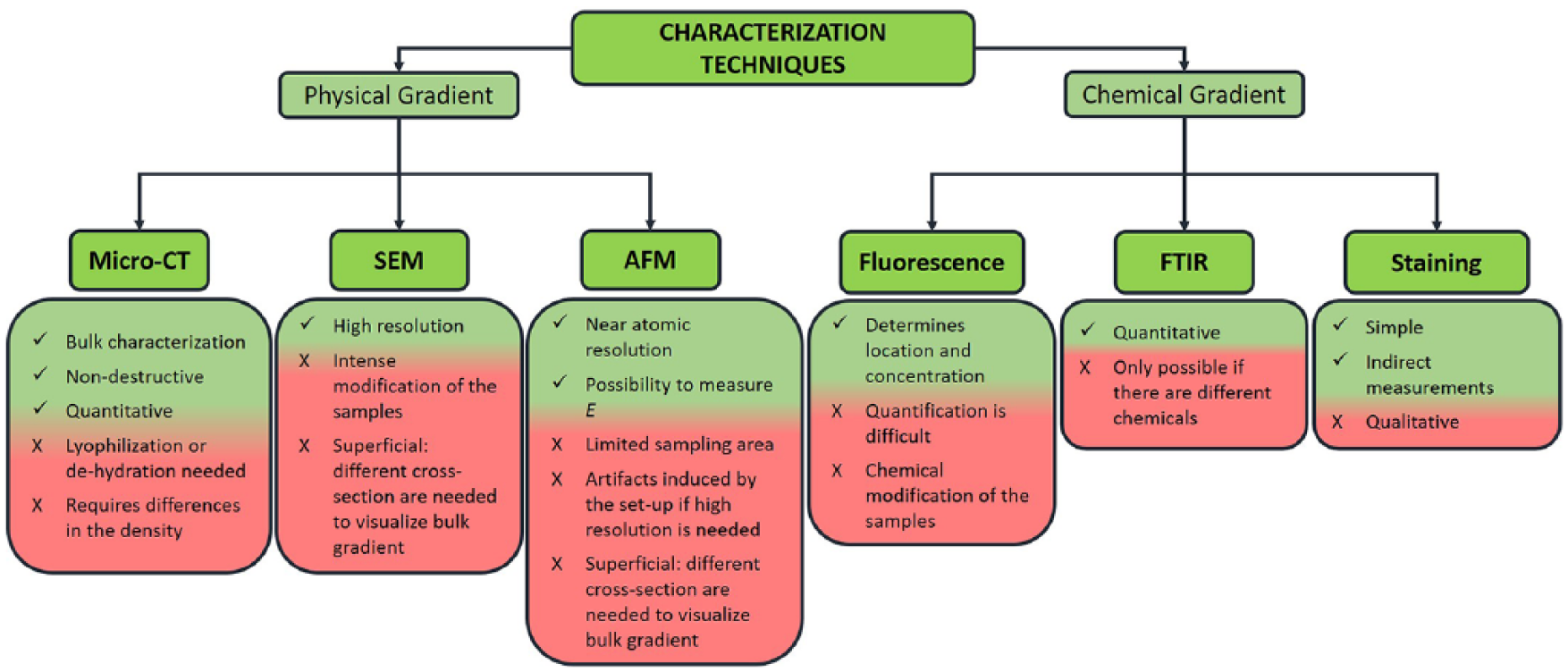
Main techniques used to characterize physical or chemical gradients, with respective advantages and disadvantages.
Conclusions
All biological structures display variable physicochemical and mechanical properties that result in the anisotropic nature of any biological tissues. Aiming to produce bioinspired structures, materials with graded microscopic arrangements must be engineered.
In this review, examples of the production of graded structures indicate the availability of different methods. Among them, rapid prototyping techniques are intrinsically designed to control the architecture of materials and can be further exploited to engineer the topographical variation of different key parameters, such as composition, geometry, and mechanical properties.
Until now, the main application of graded structures is confined to studying the effect of each varying parameter over cell activities. Moving to bioinspired structures for regenerative medicine, some examples have been reported for graded scaffolds in bone and cartilage regeneration. However, the potential of engineering graded materials is underestimated in many applicative fields, such as in-vitro models and soft-to-hard regenerative medicine.
The characterization techniques should be expanded to meet the need to examine the peculiarity of graded materials and validate the productive methods. An increasing knowledge of the production and characterization of graded structures will allow new scenarios for engineering bioinspired materials to be explored.