
Abstract
Introduction:
Unilateral external fixators are widely used in orthopedics to stabilize fractured bones and to treat limb deformities. One of the main problems is that it is difficult to detect healing status. In addition, whether load transfer progress between the fixator and bone model are the same under axial, torsional, and bending loads has not been studied.
Methods:
Therefore the main purpose of this study was to detect the load transfer process between the fixator and a bone model by measuring strains on the fixator–bone system during four healing states using experimental and finite element methods. In the experimental method, 20 strain gauges were used to measure strain on the fixator and bone model under three load conditions. Polyacetal slice models with different material properties were used to simulate the callus model during four growth states.
Results:
The results indicate that strain on the bone model increased and strain on the fixator parts decreased with maturation of the callus under axial, bending, and torsional loads. Although all curves showed a similar changing trend, they were slightly different under the three loads.
Discussion and conclusions:
This study provides a useful method to monitor the fracture healing process, and identifies the healing endpoint, detects healing status, and provides useful information for the orthopedist.
Keywords
Introduction
Unilateral external fixators are widely used in orthopedics to stabilize fractured bones and to treat limb deformities. Unilateral fixators are often utilized due to their comparatively low invasiveness and low cost. The effectiveness of elastic fixation in various clinical applications has also been reported. 1 An external fixator system is mainly responsible for load transfer through the fractured bone. 2 The external fixator acts as a mechanical bridge between the fracture fragments, allowing load transfer between the broken bones, and reducing inter-fragmentary movement between fracture fragments, which helps create a favorable mechanical environment for fracture healing. Load is shared by the fixator and fractured bone in proportion to the relative stiffness of the fixator and callus.3,4 As bone regeneration (such as during fracture healing) is influenced by mechanical loading,5–9 the in vivo mechanical environment inside the callus and around the fixator may influence the biological response of fractured bone.10,11 Therefore, the process of bone healing can be predicted by measuring the strain changes on the fixator and bone. 12 In addition, bone healing is sensitive to mechanical stability of the fixator, which depends on the material and geometric characteristics of its components and its geometric configuration.13,14
Fracture healing is a complex process that has been widely studied. Clinically available assessment methods, such as plain radiography and manual examination of the fracture movement, strongly depend on clinical experience, which may cause an incorrect determination of the healing status of a fractured bone.15,16 However, these radiological images do not provide information about callus strength that would be helpful for therapeutic decisions. Several non-invasive biomechanical methods have been proposed to assess the healing status of a fractured bone during the healing process.17,18 Others have monitored mechanical stiffness by measuring displacement of the fractured site under an applied load.18–22 As resonant frequencies are essentially related to structural stiffness, measuring the lowest resonant frequency has been proposed as an objective way to predict healing status of fractured bones.23–26 Chen et al. provided a theoretical method for effective stiffness to predict the healing process of fractured long bones. 27 However, many questions remain unsolved. One of the main problems when treating bone fractures is that it is difficult to detect the healing process and assess the healing endpoint. In addition, whether the load transfer process between the fixator and bone model is the same under axial, torsional, and bending loads has not been discussed. An easy method to monitor fracture healing could help in the early diagnosis and treatment of delayed unions and non-unions. It could also help to identify the healing endpoint and prevent unnecessary long treatments or incorrect timing for removal of the fixation device. 28
The main purpose of this study was to detect the load transfer process in a fixator–bone model under three load conditions using experimental and finite element (FE) methods. The load transfer process between the fixator and bone models was investigated by measuring strain on the fixator–bone system at four growth states when an axial, torsional, or bending load was applied. Among the various load conditions, it is important to know whether the load transfer between the fixator and bone model provides similar information. This study provides a new method to assess the healing process, identify the healing endpoint, and detect healing status as well as providing useful information for the orthopedist.
Materials and methods
Fixator–bone system model
In this study, an external tibial fixator (Dyna-extor, South Korea) was constructed and tested. Two polyacetal bars with Young’s modulus (16.5E+09 N/m2) simulating an intact tibia were used (32 mm in diameter and 180 mm in length of one side of the polyacetal model) and fixed with six pins (6 mm in diameter), three on each side of the polyacetal model. The space between the most inner pins was 200 mm, and the distance between the bone model and the fixator was 45 mm. The distance between the two pins on the two sides of the fixator was 20 mm. The fracture gap was 5 mm. Polyacetal bars have been used by many researchers to simulate a fractured bone model,29,30 so it was rational to use them while investigating the mechanical properties of a fixator–bone system.
In this study, the external fixator worked as a load cell in which inter-fragmentary movement was correlated to micro-deformation in the fixator–bone model and the load applied to the bone model. Therefore, the load transfer process was estimated by measuring strain on the fixator and polyacetal model during the healing process. 31 Thus, 20 strain gauges were used to measure the variation in strain on the fixator–bone model at the four healing stages, as shown in Figure 1(a). Twelve strain gauges were used to test variations in strain on the bone models at the four growth stages. Six strain gauges were used for the proximal bone model because three strain gauges in the axial direction and other three strain gauges in the tangential direction were uniformly distributed on the circumferential surface of the model. Thus, the average values of the three strain gauges in the axial and tangential directions were used as the axial strain and tangential strain values of the proximal bone model to reduce measurement error. Six strains gauges were used for the distal bone model; three strain gauges in the axial direction and three strain gauges in the tangential direction, which were also uniformly distributed on the circumferential surface of the distal bone model, as shown in Figure 1(b). Similarly, the average values of the three strain gauges were used as the axial strain and tangential strain values for the distal bone model.
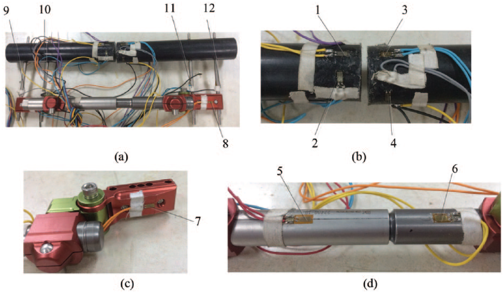
The distribution of strain gauges on the fixator–bone model.
Eight strain gauges were applied to measure strain on the fixator model. Two strain gauges were used on the distal and proximal bars, as shown in Figure 1(c). The fixator bar also had two strain gauges on the distal and proximal ends of the fixator bar, as shown in Figure 1(d). In addition, four strain gauges were used to measure the proximal lateral pin, the proximal medial pin, the distal lateral pin, and the distal medial pin, as shown in Figure 1(a).
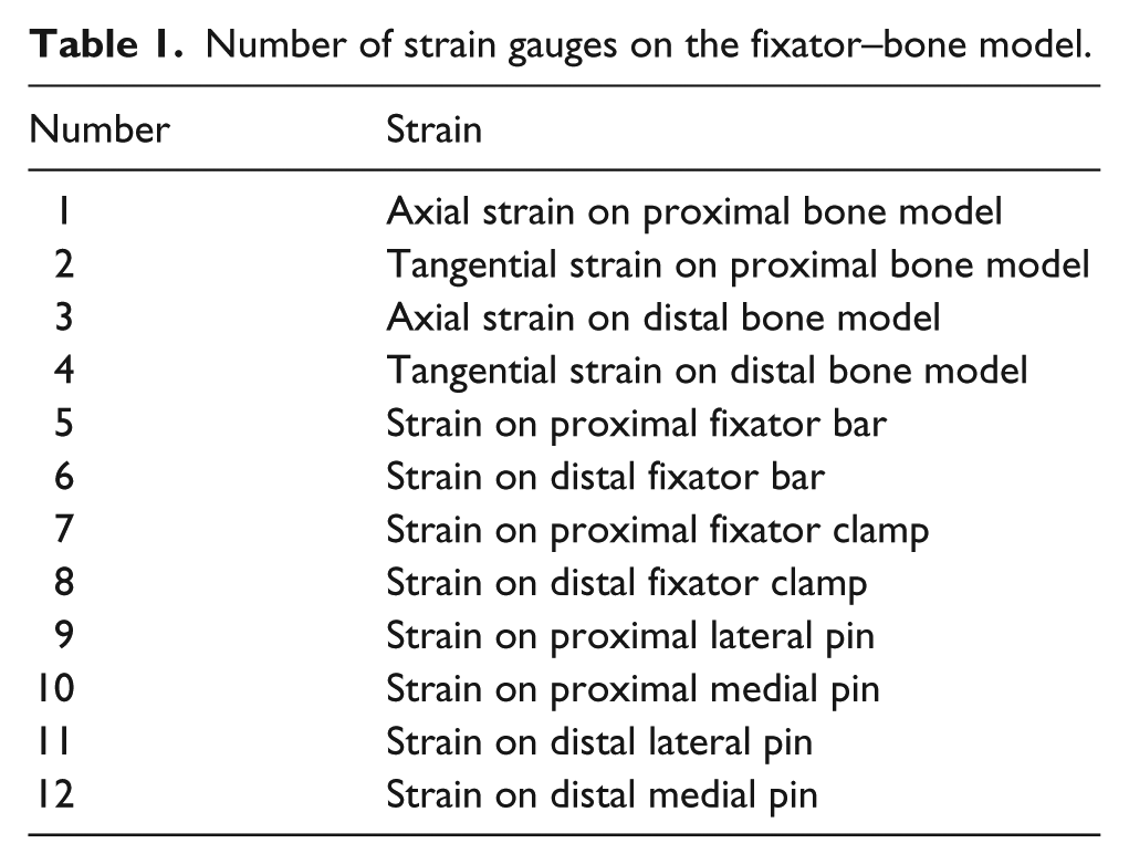
The 29 strain gauges were numbered to clearly observe the strain results, as shown in Table 1.
Number of strain gauges on the fixator–bone model.
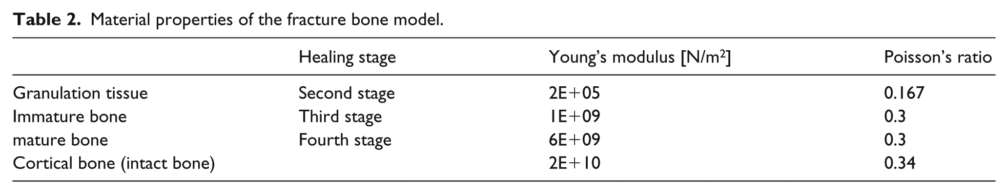
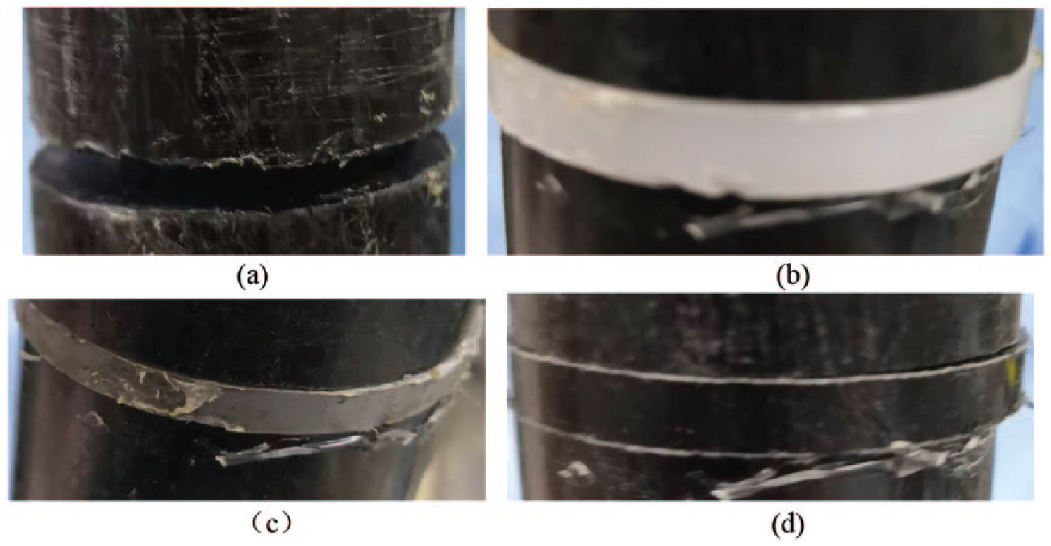
The progression of healing is usually represented by gradual increases in Young’s modulus of the callus at the fracture site.26,32 Therefore, polyacetal slice models with different material properties were used to simulate the callus during the four growth states. Intact bone properties are closely related to cortical bone properties. 33 In the first healing state, a fractured bone initially has a gap without callus tissue, so the fracture site is empty. In the second healing stage, the material properties of the callus are low, as Young’s modulus of the healing callus is main contributor to the granulation tissue.34,35 In the third and fourth healing stages, immature and mature bone are modeled as immature and mature callus. 33 The different isotropic material properties in the callus model are shown in Table 2, which defines the different healing stages. The material properties for the callus model are based on the values given by Lacroix and Prendergast. 36 Polyacetal slice models were used to simulate the callus during the different healing stages, as shown in Figure 2.
Material properties of the fracture bone model.
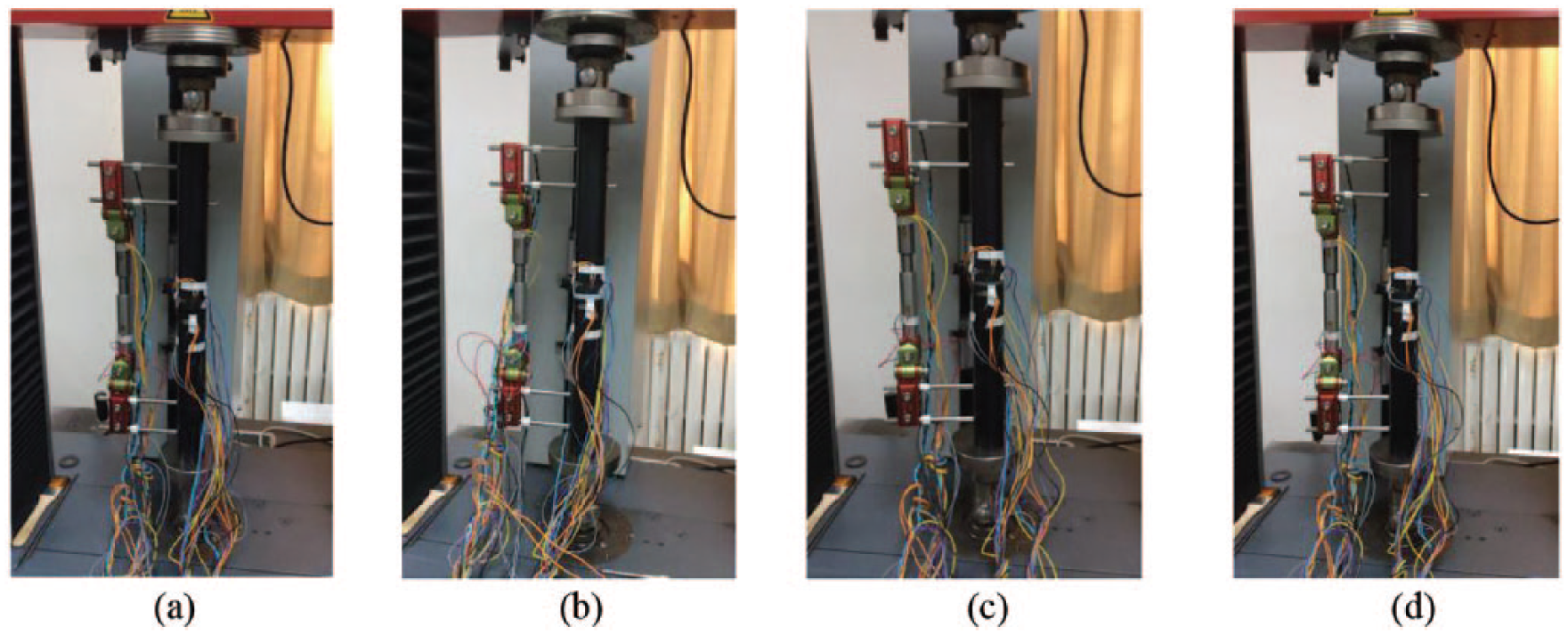
Experimental testing of the fixator–bone model under compression load at four growth states.
Experimental test setup
Four fixator–bone systems with different polyacetal slices were used to simulate the four different fracture healing states. Compression testing was conducted in the laboratory, as shown in Figure 3. The fixator test on axial compression was performed in a materials testing laboratory using a universal material testing machine (Zwick Roell, Ulm, Germany). During the testing, the intensity of the load (0–600 N at the rate of 5 N/s) on the proximal bone model was controlled, and the distal bone model was fixed. The magnitude of the strain was recorded by a real-time effector under an axial load.
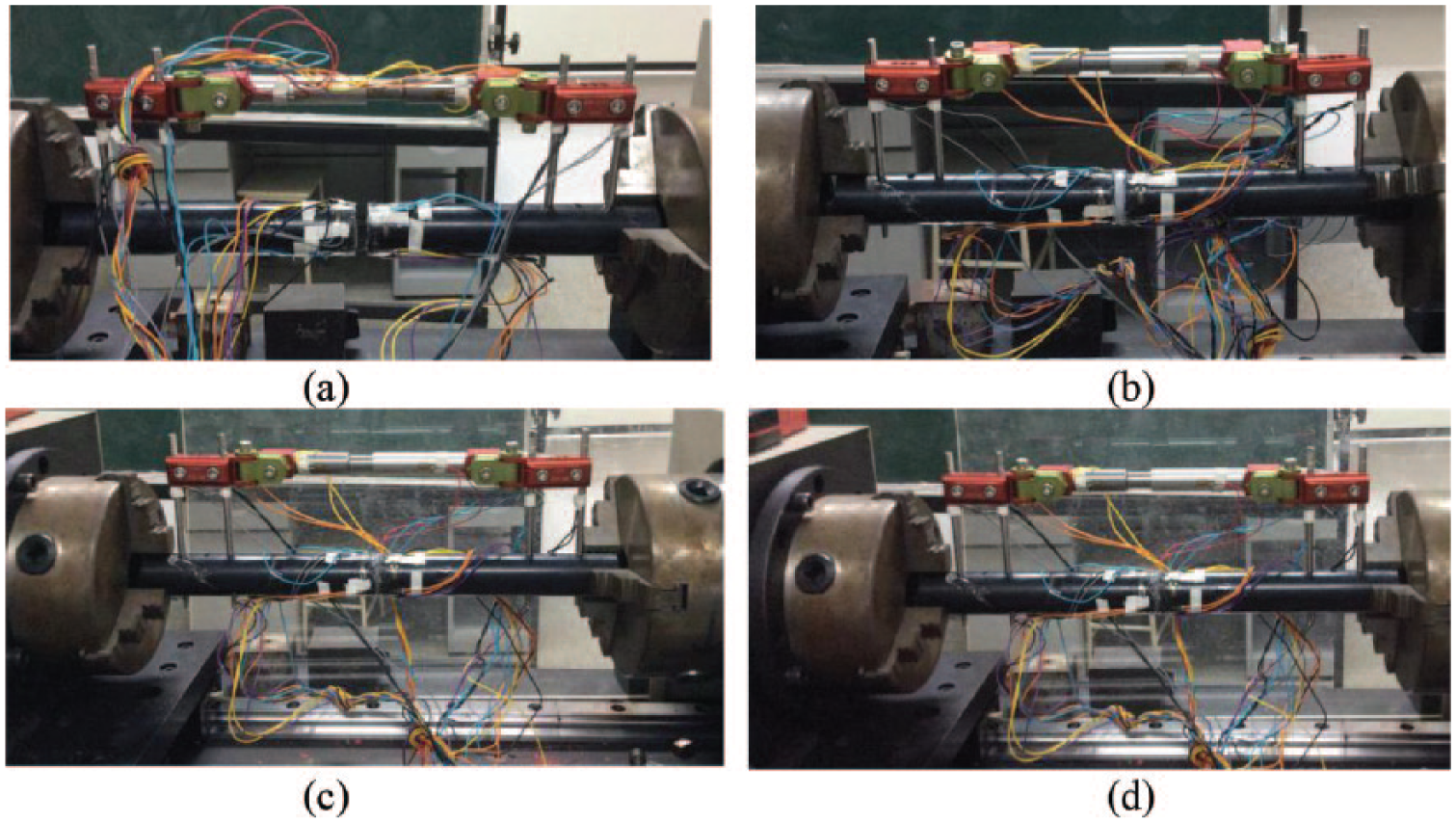
Experimental testing of the fixator–bone model under torsional load at four growth states.
Testing under a torsional load was carried out by a fixator–bone system with different polyacetal slice models to simulate the different healing states. The torsional test was conducted with a maximum load of 15 N m (0–15 N m at the rate of 3 N/s). We placed a constraint in the form of a cylindrical bearing at the end of the upper segment of the bone model, as shown in Figure 4.
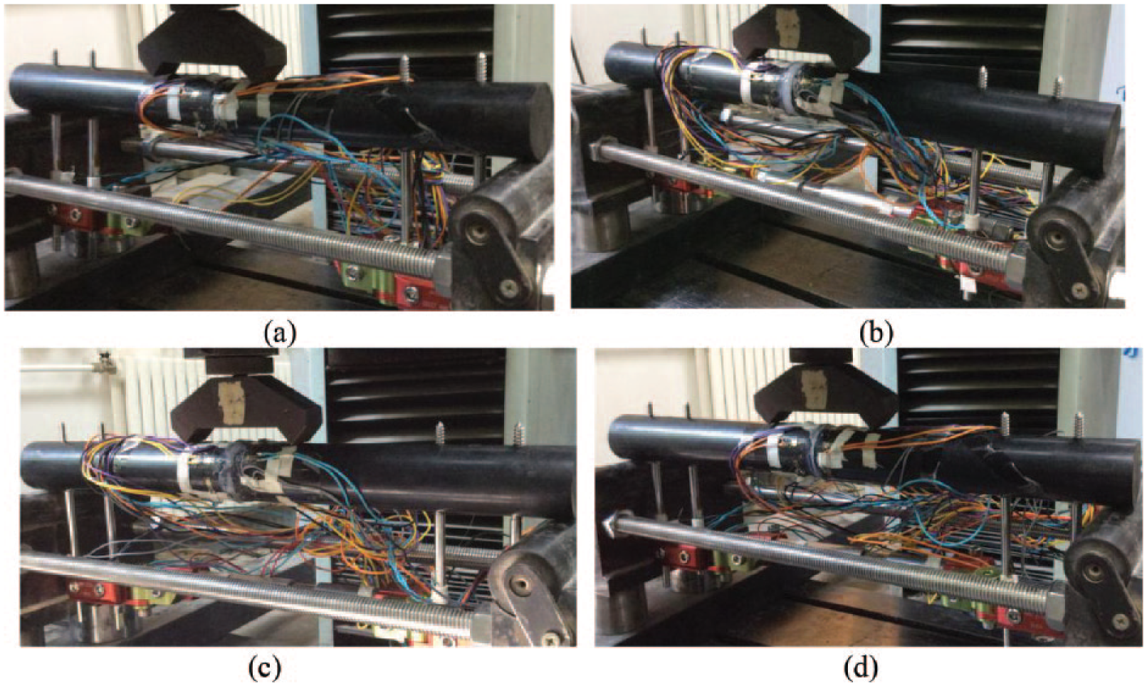
Experimental testing of the fixator–bone model under bending load at four growth states.
The bending tests were conducted on the fixator–bone system with different polyacetal slices to simulate the different healing states. The maximum load was 500 N, with a loading and unloading speed of 5 N/s. The tests were carried out in an asymmetrical fashion, using a servohydraulic testing machine LFV-50-HH (Walter Bai, Löhningen, Switzerland; Figure 5), and the DIGWIN 2000-EDC120 digital control system.
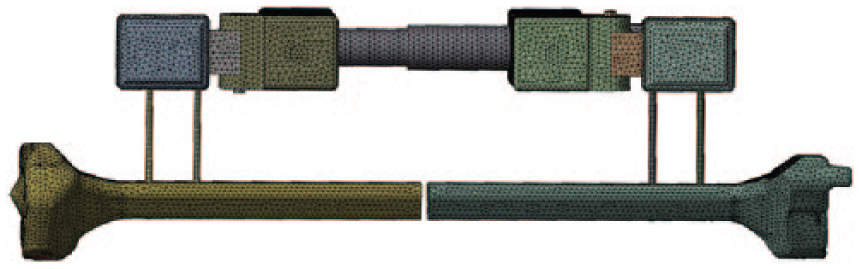
Finite element mesh of fixator–bone system.
Finite element model
Computed tomography (CT) images of the right lower limb were used to establish the FE bone model. The slice thickness of the CT images was 1.5 mm in a 512 × 512 matrix. The DICOM data set, which consisted of 225 CT images, was imported into Mimics (software version 15.1, Materialise, Leuven, Belgium) to reconstruct the surface geometry of the tibia. The external fixator systems were designed using three-dimensional computer aided design software (Solidworks 2012, Dassault Systems; Solidworks Corp. Waltham, MA, USA).
The STL files of the bones were imported into ANSYS (ANSYS Software, Canonsburg, PA, USA) and meshed with tetrahedral elements. The optimum mesh size for the bone was 3 mm and that for the external fixator was 1 mm. The fixators were meshed with four noded tetrahedral linear elements. The total number of elements and nodes for the fixator model and bone were 624,000 and 139,000 and 245,000 and 75,000, respectively. The contact body between the external fixator and the bone was set with a friction coefficient of 0.4 based on a previous study. 37 The FE mesh of the fixator–bone model is shown in Figure 6. The Young’s modulus of the bone and callus at the different healing stages used in the FE simulations are shown in Table 2. The Young’s modulus and Poisson ratio of the fixator were 2.11E+11N/m2 and 2.66, respectively.
Loading and boundary condition of finite element model of the fixator–bone system under axial, torsional, and bending load.
Loading and boundary conditions
The load conditions set for the FE model were the same as those used for the experimental measurements to test the correctness of the experiment. The distal bone end was fixed, and the proximal bone end was subjected to an axial force (F = 600 N) to measure axial stiffness, as shown in Figure 3. The distal bone end was fixed and the proximal bone end was subjected to a specific torque value (T = 15 N m/degree) to measure torsional stiffness, as shown in Figure 4. The two loads were applied 90 mm away from the fracture gap (P = 600 N) to assess four-point bending stiffness (Figure 5). The degrees of freedom of the bone were fixed. The loads were applied onto the eight nodes surrounding the loading points to avoid concentrating apparent stress. The loading and boundary conditions for the first stage are shown in Figure 7. The loading and boundary conditions were the same as for the other stages discussed above.
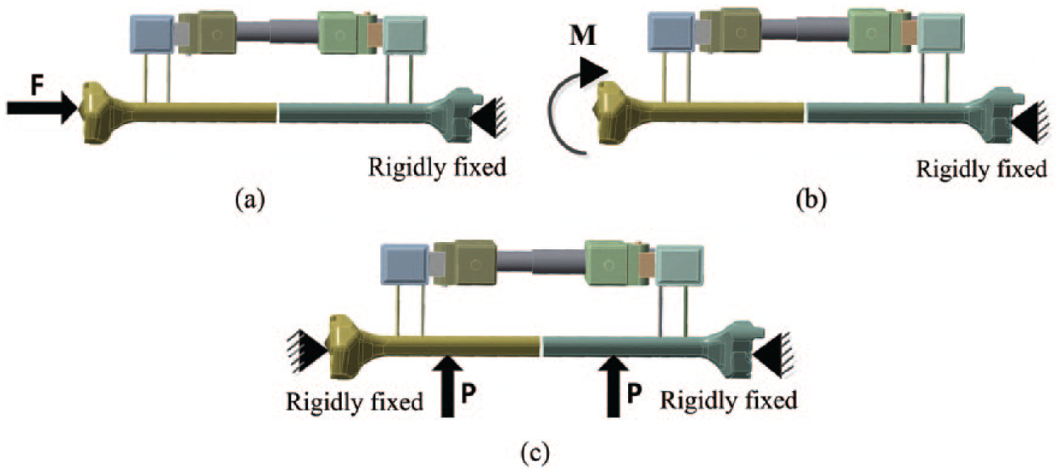
Loading and boundary conditions for the first stage.
Results
The experimental and FE results of strain on the fixator system
Figure 8 shows the evolution of strain on the fixator–bone system under an axial load during the four different fracture healing states in the experimental and FE results. All curves exhibited three parts, such as stages 1–2, 2–3, and 3–4, which corresponded to early growth of soft tissue at the fracture gap; bony bridging of the fracture gap; and maturing of the callus, respectively. Figure 8(a) shows that the strain for all cases in the bone model increased approximately 15% from stage 1 to stage 2; strain rose quickly from 15% to 85% after the bone bridged the fracture gap at stage 3; the curves increased very slowly after stage 3, and gradually became flat. The values were approximately 85–100% from stage 3 to 4. Because the strain gauges were symmetrically distributed on the proximal and distal bone models, the tangential and axial strain values on the proximal and distal bone model were approximately the same, while axial strain was much greater than tangential strain under an axial load. In the experimental results, tangential strain changed from 23 to 130, and axial strain changed from 80 to 225 on both ends of the bone model. The FE results were slightly different; that is, tangential strain changed from 28 to 102, and axial strain changed from 70 to 195.
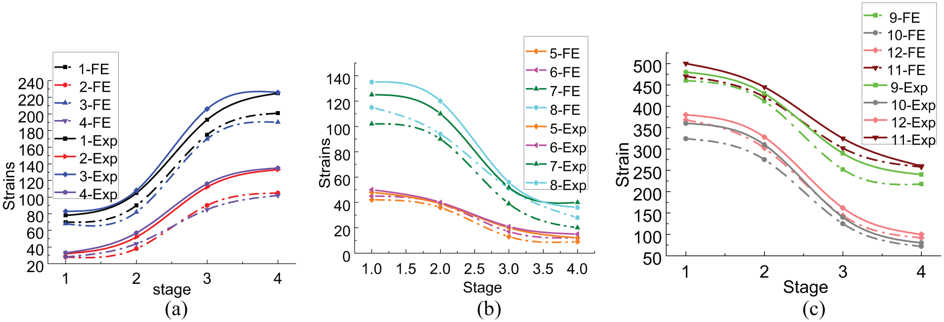
Evolution of strain on fixator–bone system under axial load at four growth states.
In contrast to the bone model, the tendency of the strain on the fixator parts was quite the opposite and presented a downward trend. As shown in Figure 8(b) and(c), the strain on the fixator parts decreased about 15% during stages 1 and 2. The strain continued to quickly decrease by approximately 70% when the callus grew into immature tissue during stages 2 and 3. Then, strain decreased very slowly to reach about 15%, as the callus became mature during stage 4. As shown in Figure 8(b), the strain on the proximal and distal pin clamps decreased from 135 to 45 and from 125 to 35, respectively with the increase in growth stage. The proximal and distal fixator bars decreased from 50 to 25 and from 53 to 30, respectively. Figure 8(c) shows that the outside pin had greater strain compared to the inside pin; the strain on the outside pin at the distal and proximal ends decreased from 500 to 260 and from 480 to 240, respectively, while strain on the inside pin decreased from 360 to 80 and from 380 to 100 at the proximal and distal ends, respectively. These results indicate that less load was carried by the fixator as bone strength increased.
The FE results revealed very similar patterns to the experimental results, demonstrating that the FE model predicted similar variations in the strain on the fixator parts. Strain on the proximal and distal fixator bars decreased from 45 to 25 and from 42 to 20, respectively. Strain on the proximal and distal pin clamps decreased from 118 to 40 and from 100 to 30, respectively. Strain outside the pins at the distal and proximal ends decreased from 480 to 242 and from 460 to 212, respectively. Strain inside the pins at the distal and proximal ends decreased from 368 to 92 and from 324 to 72, respectively.
Figure 9 presents the evolution of strain on the fixator–bone system under a bending load during the four growth states. The curves had very similar patterns, as shown in Figure 9, and also exhibited three distinct stages. Strain changed very slowly during the early and late healing stages, and decreased by about 15%. All curves changed rapidly (about 70%) during bridging of the fracture gap from stages 2–3, but did not change much with the further increase in the Young’s modulus of the callus model.
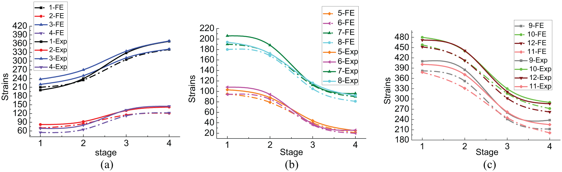
Evolution of strain on fixator–bone system under bending load at four growth states.
Although the general variations in strain under the axial and bending loads were consistent, there were some differences. The bone model, fixator bar, and fixator clamps supported higher strain under a bending load compared with an axial load. As shown in Figure 9(a), axial strain on the bone model as the callus matured increased from 220 to 370 in the experimental results, but increased from 210 to 340 in the FE results. Tangential strain on two sides of the bone increased from 82 to 142 in the experimental results and from 69 to 122 in the FE simulation. As shown in Figure 9(b), the pin clamp and fixator bar absorbed higher strain under a bending load, compared to an axial load. In the experimental results, the strain on the proximal and distal pin clamps decreased from 206 to 96 and from 194 to 92, respectively. The strain on the proximal fixator bar decreased from 103 to 25 and that on the distal fixator bar decreased from 108 to 26. In the FE results, strain decreased from 189 to 80 and from 182 to 81 on the proximal and distal pin clamps, respectively. Strain on the proximal fixator bar decreased from 95 to 21, and strain on the distal fixator bar decreased from 94 to 20.
Higher strain was detected on the inside pins under a bending load, and a slightly lower strain was observed on the outside pin when compared with the axial load, as shown in Figure 9(c). In the experimental results, strain on the outside pins at the proximal and distal ends decreased from 480 to 290 and from 472 to 286, respectively. Strain on the inside pins at the proximal and distal ends decreased from 410 to 238 and from 401 to 225, respectively. In the FE simulation, strain on the outside pins at the proximal and distal ends decreased from 458 to 272 and from 452 to 262, respectively. Strain on the inside pins at the proximal and distal ends decreased from 382 to 212 and from 378 to 201, respectively.
Figure 10 displays the evolution of strain on the fixator–bone system under torsional load during the four growth states. All curves were similar and had three characteristic stages, as shown in Figures 8 and 9. Tangential strain was larger than axial strain on the bone model when comparing axial and bending loads. As shown in Figure 10(a), the experimental and FE results indicate that larger tangential strain than axial strain was caused by the torsional load on the bone model. In the experimental results, the tangential strain on the proximal and distal bone increased from 80 to 136 and from 72 to 123, respectively. Axial strain on the proximal and distal bone increased from 63 to 112 and from 54 to 108, respectively. Moreover, the differences between the FE results and the experimental results were very small.
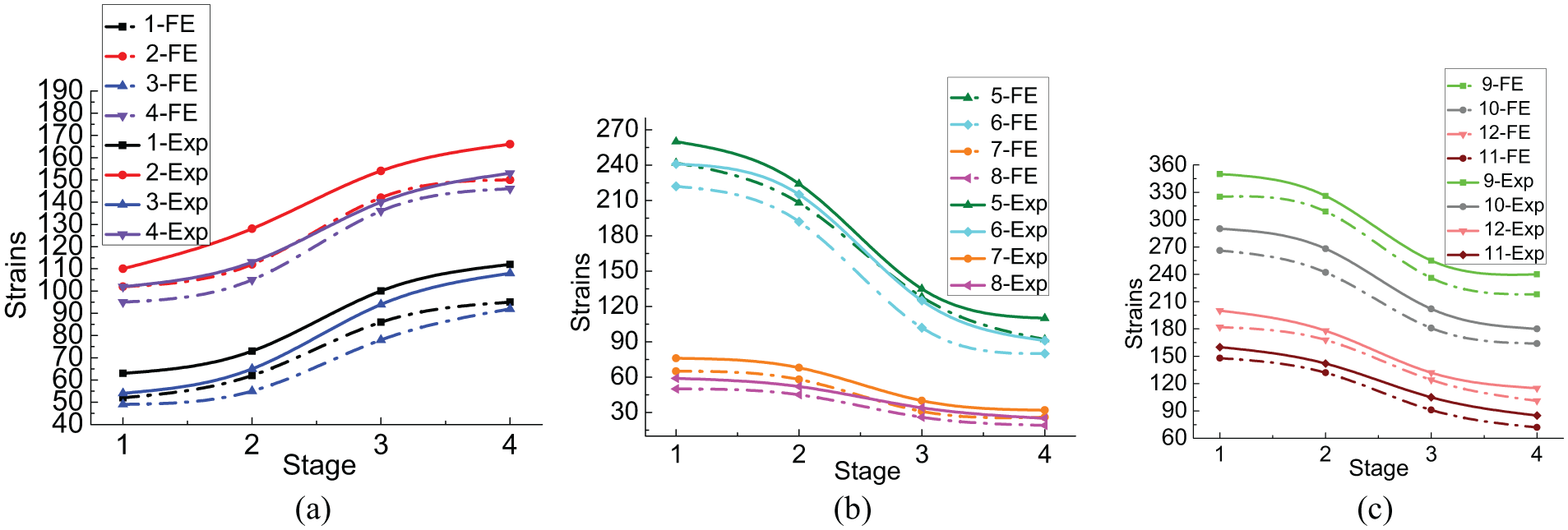
Evolution of strain on the fixator–bone system under torsional load during the four different fracture healing states. (a) Evolution of strain on the bone under torsional load during the four different fracture healing states. (b) Evolution of strain on the fixator under torsional load during the four different fracture healing states. (c) Evolution of strain on the pins under torsional load during the four different fracture healing states.
As shown in Figure 10(b), strain on the fixator bar caused by torsional load was smaller compared with axial load and bending load and the fixator clamp sustained a larger load. In the experimental and FE results, strain on the pin clamp decreased from 260 to 110 and that on the fixator bar decreased from 76 to 32.
Figure 10(c) shows the variation in the strain on the pin surface during the healing stages. Different from axial load and bending load, the maximum strain supported by the proximal lateral pin decreased from 350 to 240 and strain on the proximal medial pin decreased from 290 to 180. Smaller strain values were observed at the distal pin. Strain on the distal lateral pin decreased from 182 to 101 and strain on the distal medial pin decreased from 148 to 72.
Error between the experimental and FE results
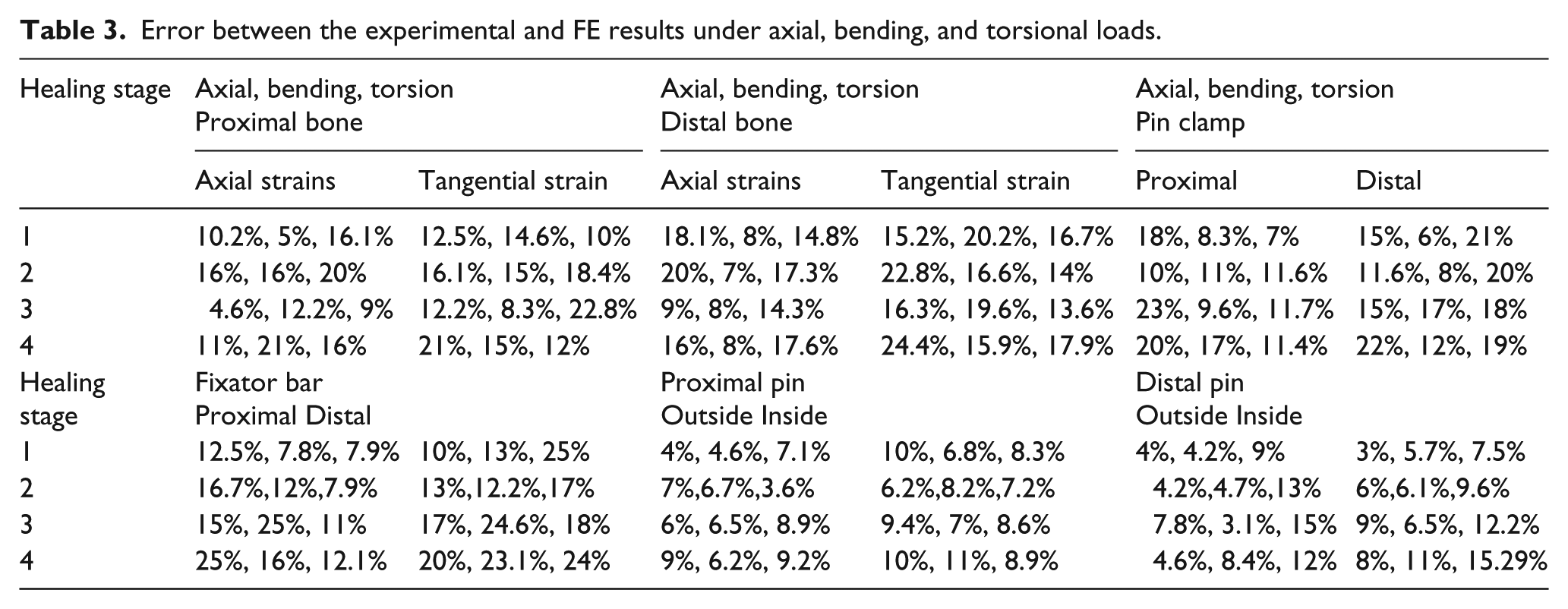
The experimental measurements and FE calculation errors for strain on each part of the fixator–bone system under axial, bending, and torsional loads are shown in Table 3. The differences between experimental measurements and the FE calculations varied between 3% and 25%. As a result, a very good correspondence was observed between the experimental results and the FE results.
Error between the experimental and FE results under axial, bending, and torsional loads.
Conclusion and discussion
In this study, we presented experimental and FE methods to monitor load transformation between the fixator and a bone model by observing the evolution of strain on each part of the fixator–bone model under axial, bending, and torsional loads at four growth states.
The results show that strain on bone model increased under axial, bending, and torsional loads with maturation of the callus, whereas strain on the fixator parts decreased. However, higher strain was observed at the pin surface during all stages of healing and the three loading conditions, which could lead to pin loosening. The fixator load-sharing results indicate that the healing callus tissues were taking on a greater proportion of tibial loading. When Young’s modulus of the callus increased, the load supported by the fixator decreased and the strain on the fixator parts decreased. The results of this study are consistent with a previous study, 38 indicating that healing callus tissues play a big role in load distribution between the fixator and the bone. The maximum load supported by the fixator decreased progressively from 20% at 7 weeks, 4% at 10 weeks, to 2% at 16 weeks post-fracture. This result confirms the results of Chen and Lui, 39 who reported that the proportion of fixator load-sharing decreased substantially as the fracture tissues matured, and the major growth of the effective stiffness in the tibia generated during the second stage bridged the fracture gap.
The increase in strain was relatively slow in the bone model at the first healing stage, indicating that premature shedding of the tibial load to the fracture site may inhibit healing as a result of overloading the callus. Because the fixator sustained heavy loads at the initial healing stage, the fracture callus may withstand a large load without damage. However strain on the bone model increased slowly at the fourth stage in experimental and FE results, which can be explained by White et al. Overloading may result in callus damage or even re-fracture before 7 weeks post-fracture. 40 Such a re-fracture has been reported, and if it is a common occurrence in fractures, suggesting less than optimal mechanical conditions routinely prevailing throughout healing. 41
Despite that the strain change rules of the fixator–bone model were consistent under the three kinds of loads, some differences existed. The bone model, fixator bar, and fixator clamps supported higher strain under a bending load than under an axial load, indicating that the fixator–bone model is less capable of bearing a bending load compared with an axial load. In addition, greater strain on the medial pin and less strain on the lateral pin under a bending load may have occurred due to changes in load direction. Tangential strain was larger than axial strain in the bone model under a torsional load, the strain on the fixator bar became smaller, because the direction of the torsional force was consistent with the direction of the tangential strain on the bone model and was perpendicular to the strain direction on the fixator bar. The difference in strain from the proximal lateral pin to the distal lateral pin tended to decrease because torsional loading was applied at the proximal end of the bone model.
The methods employed a self-validating procedure based on the experimental and FE methods by measuring strain on each part of the fixator–bone model during four healing stages through an accurate three-dimensional model of a fractured bone and fixator in the FE model. The geometries used in the FE model is simulates the real bones of the human body. Because of the limitation of experimental conditions, it is very difficult to do experiments on human body. But in this study, we use similar alternatives to mimic bones, which have same material properties and strength similar to that of the FE model. Although the geometries used in the FE model and experimental tests are different, but it does not affect the analytic results. Because they have the same material properties and same loading and boundary conditions. So they have the same strength and load bearing capacity, and they all mimic the real bone of the human body. So the FE and experimental results can be verified with each other, suggesting that these methodologies may be useful for evaluating the load transfer progress in the fixator–bone model. The significance of this study is to inform medical workers that in clinical application it is not necessary to measure the strain on the human tibia, since installing strain gauges on the bone is clearly impossible. It is only necessary to measure the strain on the external fixator to predict the healing state of the bone. The measurement of strain on the fixator is feasible; this can be done by attaching many traditional strain gauges to the fixator, or by installing strain sensor on the fixator directly. In the future, it should be possible to design a new intelligent external fixator to monitor bone healing state, which could directly measure the strain on the fixator. This article provides a method of in vitro testing to monitor bone healing. In the future, these methods can be transferred to humans to assess the healing process and determine the potential utility of this technique.
Footnotes
Declaration of conflicting interests
The authors declared no potential conflicts of interest with respect to the research, authorship, and/or publication of this article.
Funding
The authors disclosed receipt of the following financial support for the research, authorship, and/or publication of this article: This work was supported by the National Natural Science Foundation of China (grant numbers 61273342 and 51675008) and by the Beijing Natural Science Foundation (grant number 3171001).