
Abstract
Introduction:
The unilateral external fixator has become a quick and easy application for fracture stabilization of the extremities; the main value for evaluation of mechanical stability of the external fixator is stiffness. The stiffness property of the external fixator affects the local biomechanical environment of fractured bone.
Methods:
In this study, a theoretical model with changing Young’s modulus of the callus is established by using the Castigliano’s theory, investigating compression stiffness, torsional stiffness and bending stiffness of the fixator–bone system during the healing process. The effects of pin deviation angle on three stiffness methods are also investigated. In addition, finite element simulation is discussed regarding the stress distribution between the fixator and bone.
Results:
The results reveal the three stiffness evaluation methods are similar for the fixator–bone system. Finite element simulation shows that with increased healing time, the transmission of the load between the fixator and bone are different. In addition, the finite element analyses verify the conclusions obtained from the theoretical model.
Conclusions:
This work helps orthopedic doctors to monitor the progression of fracture healing and determine the appropriate time for removal of a fixation device and provide important theoretical methodology.
Keywords
Introduction
Unilateral external fixators are widely used in orthopedics to stabilize fractured bones and in the treatment of limb deformities. Unilateral fixators are often utilized due to the comparatively low invasiveness of their application and low cost. The effectiveness of elastic fixation in various clinical applications has been previously reported. 1 Clinically, half-pins are inserted through the soft tissue to the bone from one side of the limb. The procedure of inserting pins into the bone is usually performed artificially before an external fixator is applied for reduction. Under ideal situations, pins are inserted into the bone perpendicularly, and the fixator is applied in neutral or straight position. 2 However, in reality, it is difficult inserting the pins into the bone accurately and appropriately, in an ideal situation. Angular deviation of a pin may affect mechanical environment of callus in the fracture gap, bone stability, and stiffness of the fixator–bone system, and may cause incorrect diagnosis of the fracture healing. 3 The main value for evaluation of mechanical stability of the external fixator is stiffness. One of the reasons for determining stiffness of the external fixator is the stress generated in the fractured site and contact surface of the pin-bone. An increase in the stiffness of the fixator–bone system could significantly reduce the load transferred to fractured bone, help reduce the risk of weakening (relaxation) of the pins, and create better mechanical environment for fractured bone.4,5 Measuring the fixator and fractured bone stiffness in patients gives the opportunity to monitor progression of fracture healing. From the biomechanical point of view, it has been demonstrated that in fractured bone fixed by a fixator, the load is shared by the fractured bone and the fixator in proportion to the relative stiffness of the fixator and bone.6,7 Therefore, it is necessary to investigate the stiffness of the fixator and bone during the healing process, and that can help determine the appropriate time to remove the fixator for successful treatment of fractured bone. Early removals increase the likelihood of re-fractures; whereas if removal is delayed, the risk of infection is increased. Objective, quantitative and simulation methods for monitoring fracture healing could help diagnosis and treatment of delayed unions and non-unions of tibia fractures. It could also help to identify the healing endpoint, preventing unnecessary prolonged treatments or incorrect timing of fixator removal.
Studies on external fixators generally involve either experimental testing of a commercially available fixator to determine its mechanical properties.6,7 The clinically available assessment methods, such as plain radiography and manual examination of the mobility have been proved subjective and inaccurate in determining the healing status of a fractured bone. 8 Several non-invasive biomechanical methods have been proposed to assess the healing status of a fractured bone while it heals.9,10 Others have monitored mechanical stiffness by measuring displacement under applied load.11–14 As resonant frequencies are essentially related to structural stiffness, measurement of the lowest resonant frequency has also been proposed as an objective measurement of healing status of fractured bones.15–18 Chen and colleagues provided a theoretical explanation for the sensitivity of effective stiffness during the healing process of fractured long bones. 19 A new numerical model was proposed by the authors recently, which has compared the sensitivities of five assessment methods for fracture healing of long bones. 20 However, the relationship between pin deviation and the whole fixator–bone stiffness and how the force or stress transfer between the fixator and bone model have been rarely investigated during the healing process. In addition, a theoretical analysis of the fixator–bone system verified by the finite element method still seems lacking.
The main objective of this work was to develop an analytical model using Castigliano’s model to evaluate three effective bone stiffnesses, and accurately quantify the torsional stiffness, axial stiffness, and bending stiffness of bone and fixator–bone system. The effect of pin deviation on the stiffness of the fixator–bone system was also investigated. In addition, the load transferred between the fixator and bone was explored using finite element analysis (FEA), which verified the conclusions obtained from the theoretical model.
Methods
The stiffness of the fixator–bone system with the Young’s modulus of the callus at the fracture site was established. Castigliano’s theorem was used to obtain the effective stiffness of bone and stiffness of the fixator–bone system. In addition, the finite element model (FEM) of the fixator–bone system was used to verify the correctness of the Castigliano’s theory.
The theoretical model of the fixator–bone system
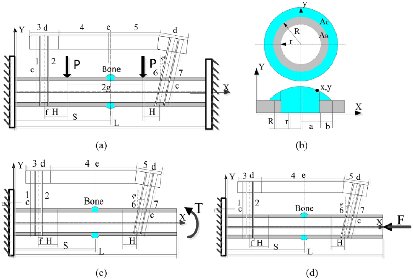
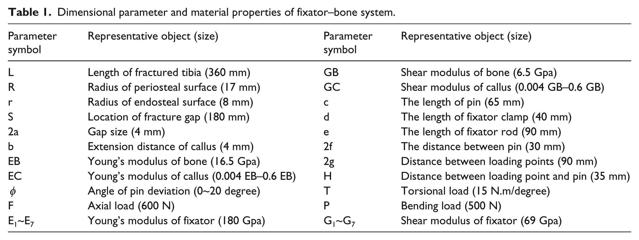
Healing progression is usually represented by gradual increases of the Young’s modulus of the callus at the fracture site. The theoretical analysis model of a fractured tibia bone and fixator are illustrated in Figure 1 (a)–(d). The tibia bone was represented by a cylinder, and the callus had a circular arc shape in the fracture gap. The dimensional parameters and material properties of the fixator–bone system are shown in Table 1.
The theoretical model for the stiffness of the fixator–bone system.
Dimensional parameter and material properties of fixator–bone system.
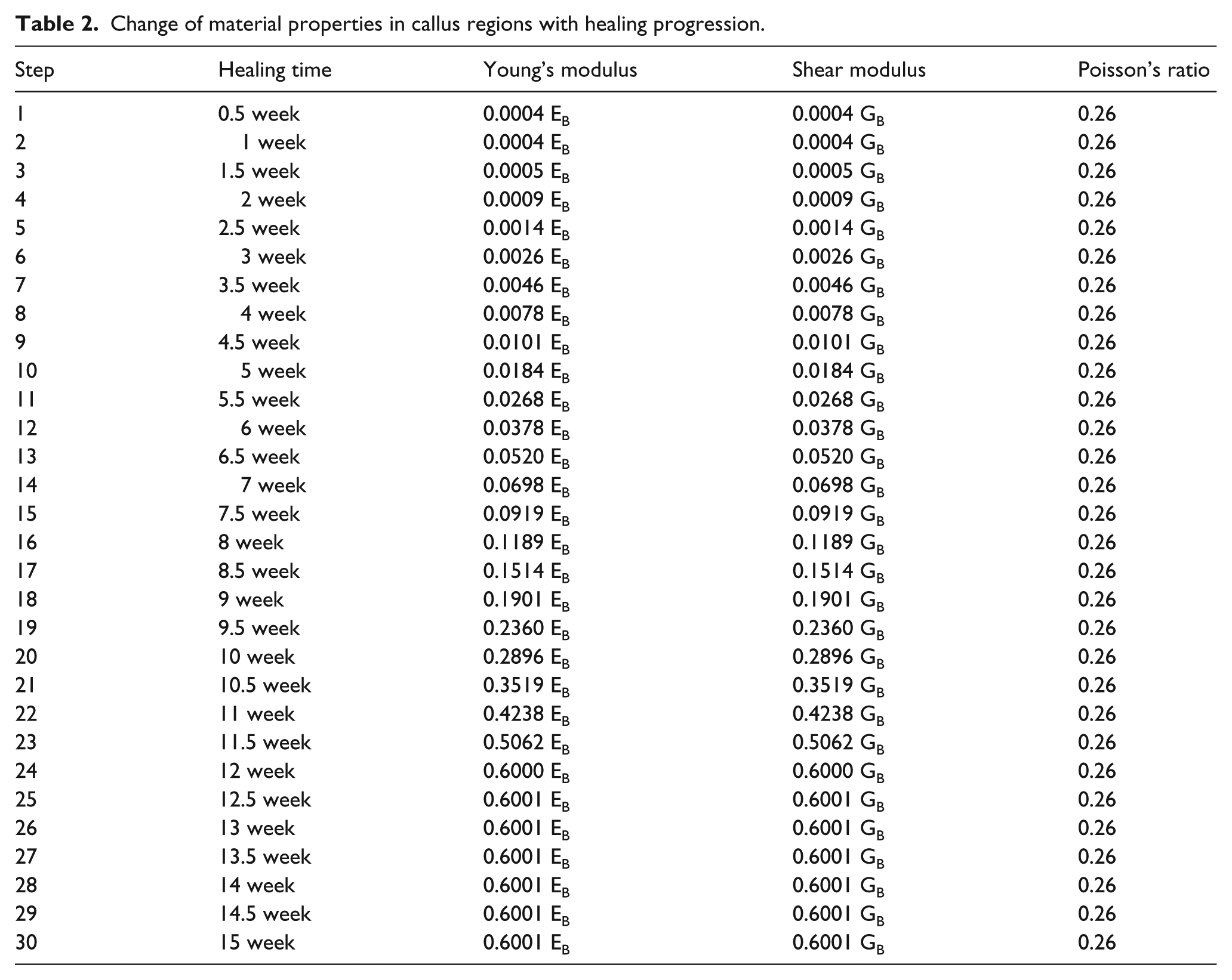
A human tibia fracture takes around 12 weeks to heal.21,22 As very little bone grows in the first 2 weeks, the Young’s modulus of callus in the first 2 weeks is mainly connective tissue. The Young’s modulus for the soft callus (initial connective tissue) was about 10 MPa, around 0.0004 that of the intact bone.21,22 At the completion of healing, the Young’s modulus of a healing callus is roughly 60% of that for the intact bone.23,24 The variations of the Young’s modulus of callus are shown in Table 2, demonstrating how it is roughly proportional to healing time. There were 30 values for the Young’s modulus of the callus applied in this article, from 0.0004 EB to 0.6 EB.
Change of material properties in callus regions with healing progression.
The radius of a cross-section at the position (x,y) was:

The cross-section at the point (x,y) consisted of two areas shown in Figure 1(b): the original callus section (AB) and the additional callus section (AC); the areas where the bone part had the callus above them were calculated by π(R2−r2) and π(yc2−R2), respectively. So, the axial rigidity (EA) of the original callus section and the additional callus (the bone part with the callus above it) were EC · AB + EC · AC and EB · AB + EC · AC, respectively.
Solution of compression stiffness of the fixator–bone system
The fixator system and fixator–bone system can be conveniently represented as spring systems, as shown in Figure 2.
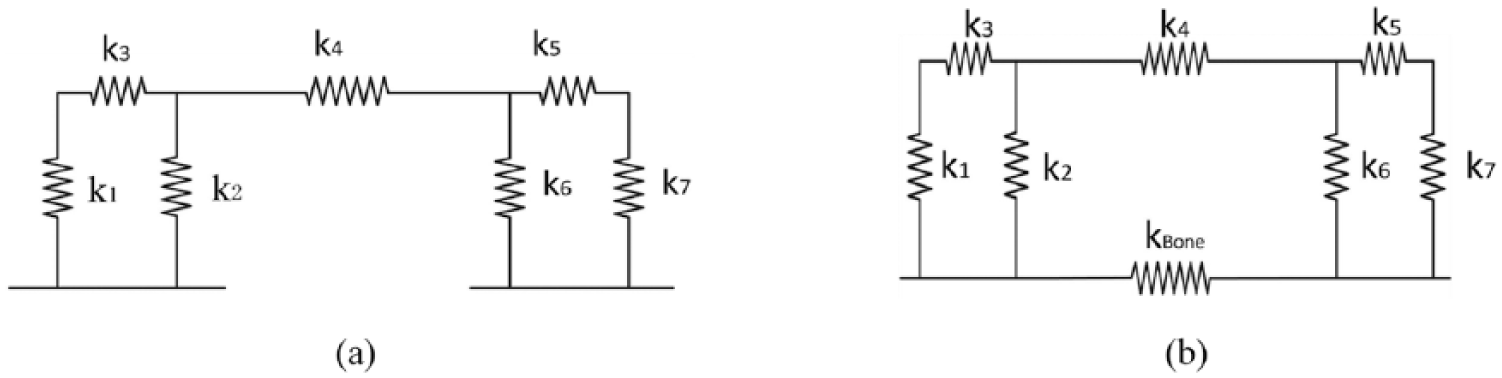
Elastic model of fixator system and fixator–bone system.
Based on the Castigliano’s theorem, axial stiffness of the fixator–bone system can be expressed as follows:
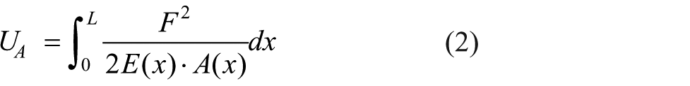
The axial force F was constant, the relative displacement, δA, can be obtained:
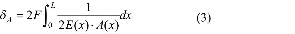
The axial stiffness (k = F/δA) was defined as:
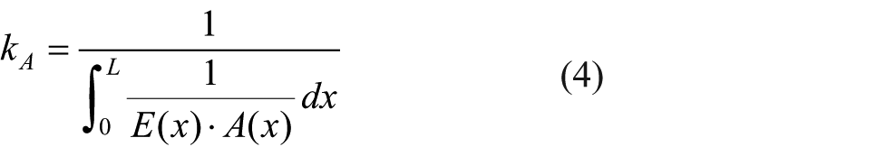
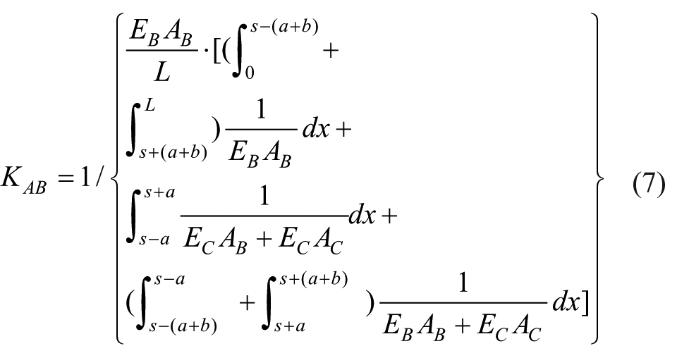
The stiffness for the corresponding intact bone is a constant value, which can be expressed as kBA1 = E(B)·A(B)/L. Thus, the effective stiffness of the fractured bone under axial load was defined as:
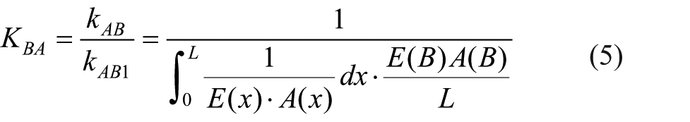
According to equations 2–4, the axial stiffness of bone can be solved by the following formula:
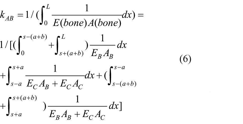
According to equations 2–5, the effective axial stiffness of bone was defined as:
The fixator system consists of 7 parts, the axial stiffness of proximal pin 1 and 2 can be expressed as:
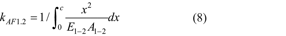
The axial stiffness of fixator bodies (equations 3–5) can be expressed as:
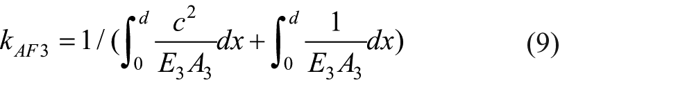
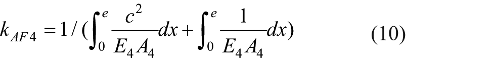
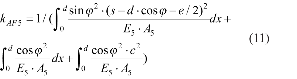
The axial stiffness of the distal pin (equations 6 and 7) can be expressed as:

According to the equations 8–12, the overall axial stiffness of the fixator system can be calculated as:
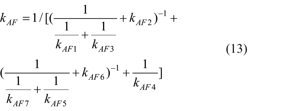
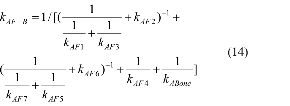
According to the equations 6 and 8–12, the axial stiffness of the fixator–bone system can be defined as:
The same method can be used to solve the effective torsional stiffness and effective bending stiffness of bone, as well as torsional stiffness and bending stiffness of the fixator–bone system. The detailed process can be seen in the supplementary material (Appendix 2.1.2).
Finite element analyses of the fixator–bone model
The fixator–bone model was established using CAD/CAM/CAE (computer-aided design/computer-aided manufacturing/computer-aided engineering), and was performed using FEA. The finite element meshes of the fixator–bone model are illustrated in Figure 3(b), which have about 800,000 tetrahedral elements. The simulations were performed in ANSYS (ANSYS Inc, Pittsburgh, USA) software. The tibia bone model had similar properties to real human bone and had been validated in a study. 25 The Poisson’s ratio was 0.26 for the callus and 0.34 for the intact bone. The convergence of the FEM was verified by checking the strain energy with about 600,000 elements.
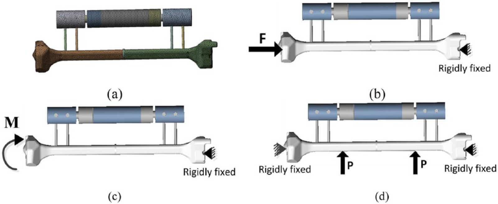
Finite element mesh, and loading and boundary conditions.
For axial stiffness, the distal bone end was fixed, and proximal bone end was subjected to an axial force (F = 600 N) (Figure 3(b)). For torsional stiffness, the distal bone end was fixed, and the proximal bone end was subjected to a torque (T = 15 N.m) (Figure 3(c)). For 4-point bending stiffness, the degrees of freedom at both ends of bone were fixed. The two loads (P = 500 N) were applied on the position 90 mm away from the fracture gap (Figure 3(d)). For these three load conditions, in order to avoid apparent stress concentration, the loads were applied onto the eight nodes surrounding the loading points.
Results
Results of the effective stiffness of the fractured bone
The effective compression stiffness, torsional stiffness and bending stiffness of the fractured bone are shown in Figure 4, which presented three stages, including the first stage (narrowing of the fracture gap) between approximately 0 and 5 weeks, the second stage (bony bridging of the fracture gap) between approximately 5 and 12 weeks, and the third stage (maturing of the callus) between around 12 and 15 weeks.
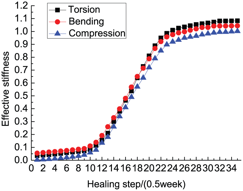
Variations of the effective stiffness of the fractured bone with healing time for three loading situations: torsion, compression, bending.
As shown in Figure 4, during the first stage between 0 and 5 weeks, the three curves exhibit a very slow upward trend; they almost reached 10%, owing to the callus comprising mainly connective tissue, and has a very low stiffness and Young’s modulus. In the second stage, initial tissue started to mature during step 10 to step 24 (5–12 weeks); the three effective stiffness curves rose quickly, reaching 95% at step 24 (12 weeks), indicating the fracture gap bridging during this period. The Young’s modulus of callus changed from 10% to 60% in this stage. In the third stage, from 12 to 15 weeks, the three stiffness curves rose very slowly after step 24 (12 weeks), predicting the completion of the second stage, when fractured bone stiffness is almost no longer increased, and the fractured bone is almost healed.
Results of stiffness of the fixator and the fixator–bone system
Figure 5(a)–(c) exhibits the change trend of compression stiffness, bending stiffness and torsional stiffness of the fixator and fixator–bone system when angle deviation exists. With an increase of deviation angle, the compression stiffness of the fixator and fixator–bone system shows an upward trend in Figure 5(a), while the compression stiffness of the fixator–bone system shows a gentle increased trend relative to that of the fixator, maybe owing to the increased Young’s modulus of callus. For Figure 5(b) and Figure 5(c), the bending stiffness and torsional stiffness of the fixator is higher than that of the fixator–bone system. With an increase of pin deviation angle, bending stiffness and torsional stiffness of the fixator–bone system exhibit a slower changing trend than that of the fixator. When the pin deviation angle changed by 1°, compression stiffness increased by 0.45 N/mm, bending stiffness increased by 0.25 N/mm, and torsional stiffness decreased by 5N.mm/degree, which indicates torsional stiffness of the fixator was more affected by the deviation angle.
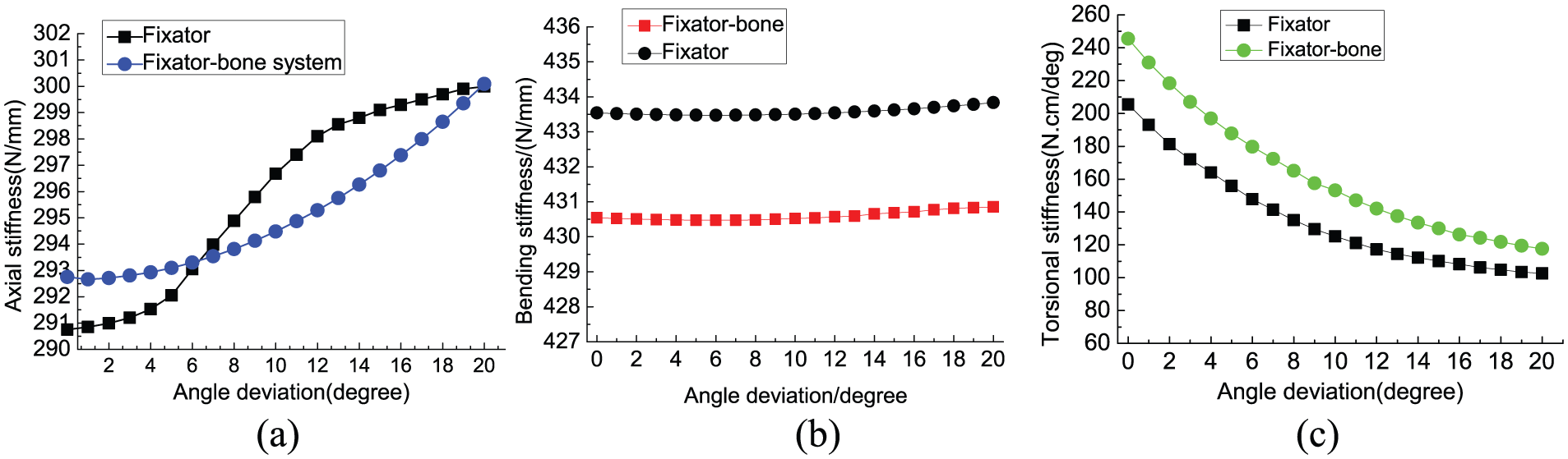
The variation of fixator and fixator–bone system stiffness when pin deviation exists.
Finite element analysis results
Figure 6 exhibits stress distribution of the fixator–bone system under axial load, according to the fracture healing time. In Figure 6(a), during the first stage, the callus is granulation tissue, so most weight is sustained by the external fixator, the highest stress value was 7.957e + 007N/m2, which occurred on the contact surface between the fixator and pin. During the second stage for Figure 6(b), the callus gradually matured, the load progressively transfers from fixator to bone, both fixator and bone bear the load, the highest stress exists on the contact surface between the fixator, and the pin is reduced, which is 3.3806e + 007N/m2. For Figure 6(c), during the third healing stage, the bone in the fracture gap is matured tissue, the maximum stress value is 2.2355e + 07N/m2, which occurred in the fracture gap region; the bone could bear most of the load at this bone maturation stage, meaning the fixator can be removed.
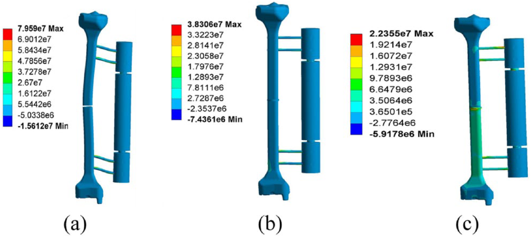
Stress distribution of the fixator–bone system under axial load.
Figure 7 exhibits the stress distribution of fixator–bone system under torsional load. Figure 7(a) is similar to axial load, under the action of 15 N.m torsional load; in the first stage, the maximum stress reaches 2.483e + 08N/m2, which occurred in the contact region of the pin and fixator. In the second stage, shown in Figure 7(b), with respect to the fixator, the bone undertakes a heavier load, indicating the load is transferred from fixator to bone. The maximum stress value of 3.1461e + 08N/m2 occurs on the contact surface between the bone and pin. In the third stage, after bone maturation, higher stress is mainly concentrated in the distal bone. Due to the smaller diameter of the pin, the maximum stress value of 8.8014e + 08N/m2 still occurs at the contact surface of bone and pin.
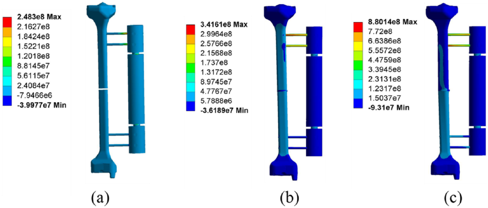
Stress distribution of the fixator–bone system under torsional load.
Figure 8 illustrates the stress distribution of the fixator–bone system under a bending load. In the first stage shown in Figure 8(a), the maximum stress value is 1.8789e + 07N/m2, which occurs on the surface of the pin. Because the callus at the fracture gap is granulation tissue, the stiffness of bone is very low, and large deformation occurs at the fracture site. Orthopedic patients are not suitable for a bearing load at the early stage of healing process. Shown in Figure 8(b), the bending load is transferred from fixator to bone, and higher stress appears at the bone surface near the pin. The maximum value of 1.4448e + 07N/m2 appears in the contact surface between the bone and pin. In the third stage, after bone maturation, the stress on the bone is increased and greater than that of the fixator, the maximum stress value of 2.5624e + 07N/m2 occurs at the fracture site.
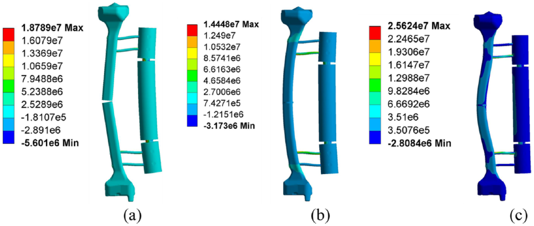
Stress distribution of fixator–bone system under a bending load.
Validation of theoretical results and finite element results
Figure 9 shows the theoretical results and finite element results of fixator–bone system for compression stiffness, torsional stiffness and bending stiffness in the healing process from 2.5 weeks to 12 weeks, in which Young’s modulus of callus changes from 0.0026 EB to 0.6 EB. For Figure 9 (a)–(c), with increased healing time, compression stiffness, torsional stiffness and bending stiffness of the fixator–bone system all show a slowly increasing trend. The three stiffness results of the finite element simulation are smaller than that of the theoretical calculation. Figure 9(d) shows the average values of three kinds of stiffness obtained from theoretical analysis, FEA and experimental data. In order to verify the theory and the finite element results, comparing these results with experimental data (Chen, 2016). 19 In experimental data, the average values of axial stiffness, torsional stiffness and bending stiffness are 290.75 N/mm,144.48 N/mm and 457.7 N.cm/degree, respectively. The boundary conditions in the experiment are consistent with the boundary conditions imposed in finite element simulation and the theoretical model: For axial stiffness, the distal bone end was fixed and the proximal bone end was subjected to an axial force (F = 600 N); for torsional stiffness, the distal bone end was fixed and the proximal bone end was subjected to a torque (T = 15 N.m); for 4-point bending stiffness, both ends of the bone model were fixed, the two loads (P = 500 N) were applied on the position 90 mm away from the fracture gap. Therefore, the correctness of the finite element and theoretical models can be verified by comparing the experimental results, the finite element and the theoretical results. The average values of axial stiffness, torsional stiffness and bending stiffness from theoretical analysis are 292.75 N/mm,195.4843 N/mm, and 430.542 N.cm/degree respectively; the average values of these stiffness obtained from finite element simulation are 273.34 N/mm, 185.1536 N/mm, and 420.901 N.cm/degree, respectively. Compared with the experimental results, the theoretical analysis errors are 6%, 28% and 9.5%, respectively, the finite element simulation errors are 6.8%, 28.04% and 11.56%, respectively. The correctness of the theoretical analysis and finite element simulation can be verified by these error results.
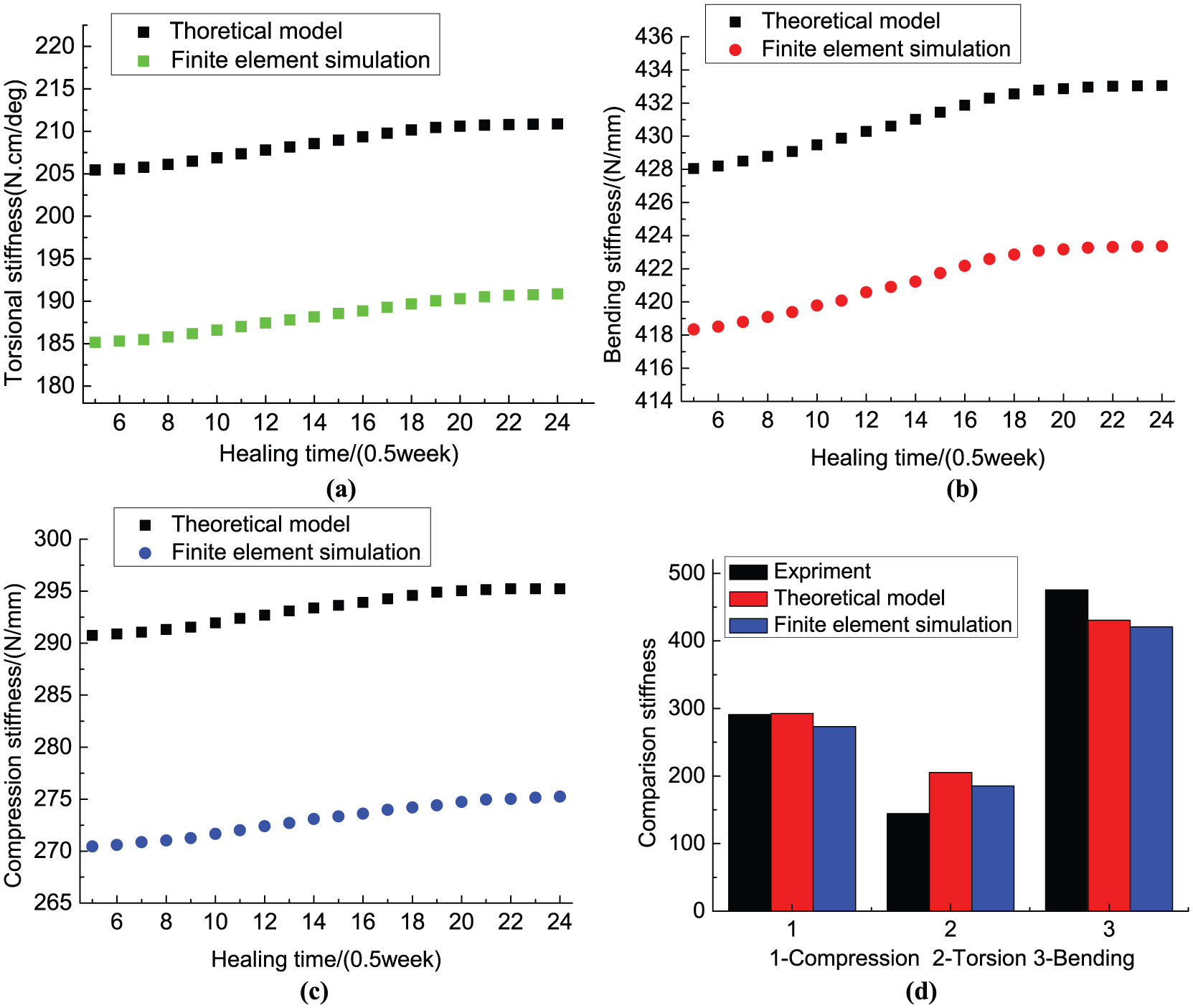
Comparisons of results for torsional stiffness, compression stiffness and bending stiffness obtained from the theoretical model, finite element simulation and experimental data (Chen, 2016), 19 with healing time from 2.5 weeks to 12 weeks.
Discussion and conclusion
In this work, we have proposed a new, energy-based analytical model to study mechanical characteristics of the fixator–bone system during the healing process, in particular, to quantify the stiffness of the fixator–bone system and bone, and predict bone growth trend. The method is an effective tool for studying biomechanical properties of the fixator–bone system in a mathematical model. In the theoretical analysis, the fixator behaves more like a multibody system rather than a single unit. Although there are some deviations between the experimental results and the theoretical calculation, the method is still a powerful tool for studying the stiffness characteristics of the fixator–bone system in a mathematical framework.
In the calculation of effective torsional stiffness, effective compression stiffness and effective bending stiffness of a tibia bone, finding they have similar prediction results for bone healing status, helps to explain the results reported by previous experimental test. 26 Due to the rapid increase of bone stiffness during the bridging-of-the-fracture-gap stage, and slow increase at the third stage, while callus stiffness increased, bone stiffness did not increase after bridging of the fracture gap, suggesting re-fracture of bones may occur after the external fixators are removed. When pin deviation angle increased, the bending stiffness and compression stiffness of the fixator was not apparent; torsional stiffness decreased rapidly because the change in the direction of the pin may cause the change of load direction acting on the fixator. This result is similar to that in a previous study. 27 Owing to the stiffness of the bone being less than that of the fixator, the stiffness of fixator–bone system is similarly lower than that of the fixator.
FEA can help us understand the biomechanical environment of bone and predict the load transfer between the fixator and bone in the healing process. Under action of three kinds of loads, the load transfer processes between the fixator and bone are similar. In the beginning stage, the callus tissue consists of fluid components and has very low stiffness. Owing to the bone stiffness being very low, the load is mainly carried by the fixator. The maximum stress occurs on the contact surface between the fixator and the pin. During the second stage, the callus grows into immature bone tissue, the stiffness of the bone increases, the load distribution between the fixator and bone changes, and stress begins to transfer from fixator to bone. In the last stage, stress is mainly concentrated on the bone, allowing the fixator to be removed, with bone able to bear a considerable part of the load. The results of this study are consistent with the in vivo test and simulation results obtained from previous researchers.27–29 In addition, for the three kinds of loads, the results of fixator–bone stiffness obtained from the theoretical model were verified by the finite element simulation.
The aim of this research was to develop a theoretical model and finite element method to compare three kinds of stiffness of the fixator–bone system during the healing process. The major limitation of the present work is that all calculations are based on a linear theory. Furthermore, as the algorithm of fracture healing is very complicated,30–32 the process of bone growth was simply represented by the increase of Young’s modulus during different healing periods regardless of the irregularity of callus shape. In addition, this work considers a less simplified healing process; but in the actual healing process, the factor that affects evolution of bone strength is not just stiffness, but the physiological environment inside the human body. Meanwhile, age and physical condition also have some influence on the healing process of bone. These limitations, however, do not jeopardize the importance and correctness of the results obtained in this paper; this study still provides a new and effective method and theoretical basis for the orthopedic doctors.
Supplemental Material
Supplementary_Material_PDF – Supplemental material for A theoretical analysis and finite element simulation of fixator–bone system stiffness on healing progression
Supplemental material, Supplementary_Material_PDF for A theoretical analysis and finite element simulation of fixator–bone system stiffness on healing progression by Jianfeng Li, Xia Zhao, Xiaojie Hu, Chunjing Tao and Run Ji in Journal of Applied Biomaterials & Functional Materials
Footnotes
Declaration of Conflicting Interests
The author(s) declared no potential conflicts of interest with respect to the research, authorship, and/or publication of this article.
Funding
The author(s) disclosed receipt of the following financial support for the research, authorship, and/or publication of this article: This work was supported by the National Natural Science Foundation of China under Grant No. 61273342 and No. 51675008, and by the Beijing Natural Science Foundation under Grant No. 3171001.
Supplementary material
Supplementary material is available for this article online.
References
Supplementary Material
Please find the following supplemental material available below.
For Open Access articles published under a Creative Commons License, all supplemental material carries the same license as the article it is associated with.
For non-Open Access articles published, all supplemental material carries a non-exclusive license, and permission requests for re-use of supplemental material or any part of supplemental material shall be sent directly to the copyright owner as specified in the copyright notice associated with the article.