
Abstract
Introduction:
Supporting rings are becoming more widely applied as an assistant structural support. However, during the engineering design and optimization process, many tests are necessary to understand the mechanical properties of different materials and the different section shape for supporting rings.
Methods:
The key problem is to measure the radial force caused by elongation under the axes’ pressure. This cannot be measured directly through the use of sensors. The previous, simple method was to position a transfer bar into the hole on the supported wall, or use a strain gauge, which changes the contact boundary. A new method called the “semi-ring method” is proposed.
Results:
The problem can be solved well and the feasibility of this method is shown from an example of its application.
Conclusions:
An innovative method is applied in test of mechanical performance for PTFE and butyl rubber material adopted in four kinds of section shape structure supporting rings. The results and analysis can provide some beneficial references for structure design.
Introduction
The structural supporting ring has broad engineering applications as a structural transition support, such as in machine tools, ships, automobiles, aircrafts, vehicles, and aerospace equipment.1–3 The principle of its action is as follows: the structure supporting ring is arranged in the relevant shape based on space requirements, and axial load is applied to the structural supporting ring, which results in radial expansion, ensuring the structure has the function of radial support. In this, rubber and other materials can also play a role in decreasing the vibration involved.4–6 In the structural design and optimization process, it is necessary to study the mechanical performance of the structural supporting ring through a range of laboratory tests.7–9
In terms of the mechanical properties of different materials, different section shape structural bearing rings are compared, such as axial compression with axial load and radial force variation with axial compression volume changes. The axial load, which is applied by material testing machine, can be measured directly by a force sensor, and the axial compression measured using a displacement gauge. The difficulty is measuring the radial force, which is bearing the ring radial expansion function to support the extrusion of the inner wall. Unfortunately, it is impossible to introduce the force sensor directly. There have been two traditional methods. One approach is to put a hole in the circumferential direction by the support member, and introduce a transfer bar, before the transmission rod end and the force sensor are connected and fixed by the support member. The other end extends into the circumferential direction of the hole, and the end face is flat against the inner wall of the support member. Radial expansion is caused by axial load, and the radial force on the transfer bar end is transferred to the force sensor. Thus, the radial force can be measured. The other way is to introduce a thin layer of pressure sensor between the support member and the inner wall of the supporting ring to measure the radial force directionally.10–12
However, these methods will change the contact boundary, and have their own shortcomings. For the first method, the main drawbacks are: the radial hole will change the contact boundary; the transmission rod installed cannot be precisely controlled, which will badly affect the measurement results. For the other method, the main drawbacks are: although the inter-layer pressure sensor is very thin, the sensor contact pressure will increase, so the specific impact cannot be determined; the support ring space is confined – in order to lead out, the hole needs to be opened, which will affect the support ring stress situation. To solve these problems, a new measurement method – the semi-ring measurement method – is proposed in this paper, and the mechanical properties of different materials and different section shape supporting ring are researched.
“Semi-ring” measurement method
The support member is processed as a two semi-rigid ring-type structure, as shown in Figure 1(a). The A, B shown in two directions are connected respectively with the two force sensors; there is certain preload action before installation, which is produced by the interaction in the two semi-ring joints, to ensure it becomes a whole ring-type structure. According to the test results of the two force sensors, the radial line semi-ring average distributed load can be obtained by conversion of the support ring, 7 as shown in Figure 1(b), where q is the semi-ring wall circumferential line load, R is the semicircle radius, and F is the radial force action on the semi-ring.
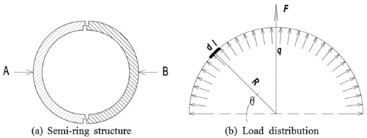
Semi-ring structure and load distribution.
Based on the mechanics of materials knowledge, the formulation will be
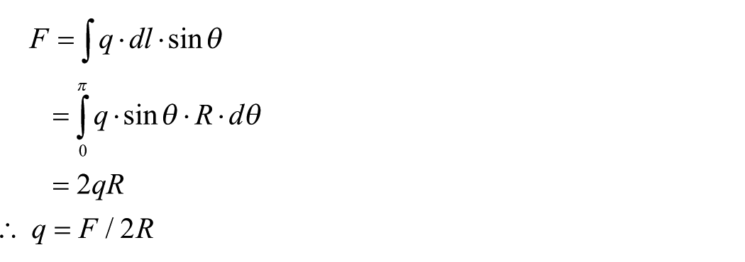
The preload applied to the semi-ring before it is installed should not be too large, and it is appropriate to enable the two semi-rings as a whole. The interaction force of the butt joint of the two semi-rings is denoted as F0. During the experiment, due to the increase of axial compression, the bearing ring radial expands to fill the gap. Once it is in contact with the inner wall of the semi-ring, there is radial load action on the support ring and semi-rings. With the increase of radial load, the interaction F0 acting on the two semi-ring interfaces decreases to zero. The force value measured by the two force sensors is equal to the radial load acting on the semi-ring and the supporting ring. The radius of semi-ring R is a known quantity; therefore, the inner circumferential direction line load can be calculated according to the force sensor measurement result needed for the support ring.
Using the above analysis, the new method was applied to assess the importance of the following issues. First, the stiffness of the connection between the semi-ring and the force sensor and stiffness of semi-ring must be satisfied. Second, the contact of semi-ring bottom end and the test machine platform should be smooth. Third, a pre-tightening force should be applied to the semi-rings before they are installed to make it complete. Lastly, the pre-tightening force should not be too large, and if the performance of the supporting rings sequence can be compared, the pre-tightening forces must be of the same value for each test in order to eliminate any influence.
Mechanical properties test of different materials for support structure rings
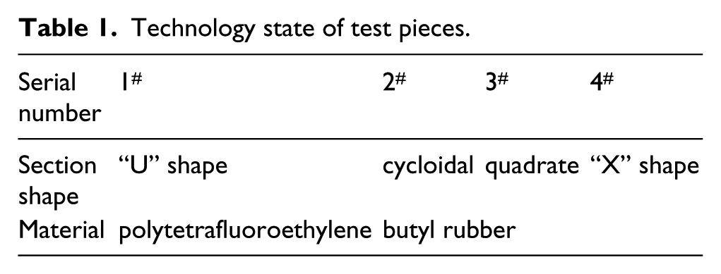
Four different section shapes of polytetrafluoroethylene (PTFE) and butyl rubber ring materials support structure rings were chosen for the mechanics performance test. The technical status of sample test pieces is shown in Table 1, and the test installation state is shown in Figure 2. In order to reduce the influence of friction, lubricating oil is applied to the contact surface between the half ring bottom surface and the mounting plate when installed. The semi-ring test measurement method presented in the previous paper is used to measure the radial force. The axial load was applied by material testing machine, and the axial compression is achieved by averaging the values of three axial displacement gauges.
Technology state of test pieces.
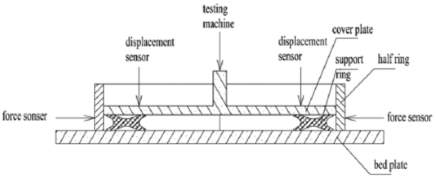
Mechanical property test of support ring.
The measurement test data of the radial force is obtained successfully. The method of radial force measurement of the fourth specimen is shown as an example in Figure 3(a), where P1 and P2 are the measurement values of the two force sensors installed pre-load after zero, respectively, and Pq is the mean value of P1 and P2. The curves in Figure 3(a) reflect the changing relationship of the radial force on the inner wall of the supporting ring and axial amount of compression. As there are certain initial gaps between the support ring and semi-ring inner wall, the radial force is always zero at the beginning of loading, corresponding to the axial compression amount 0–1 mm period in Figure 3(a). The radial forces start to increase once the initial gap is filled, and the growth rate also increases by the axial compression amount.
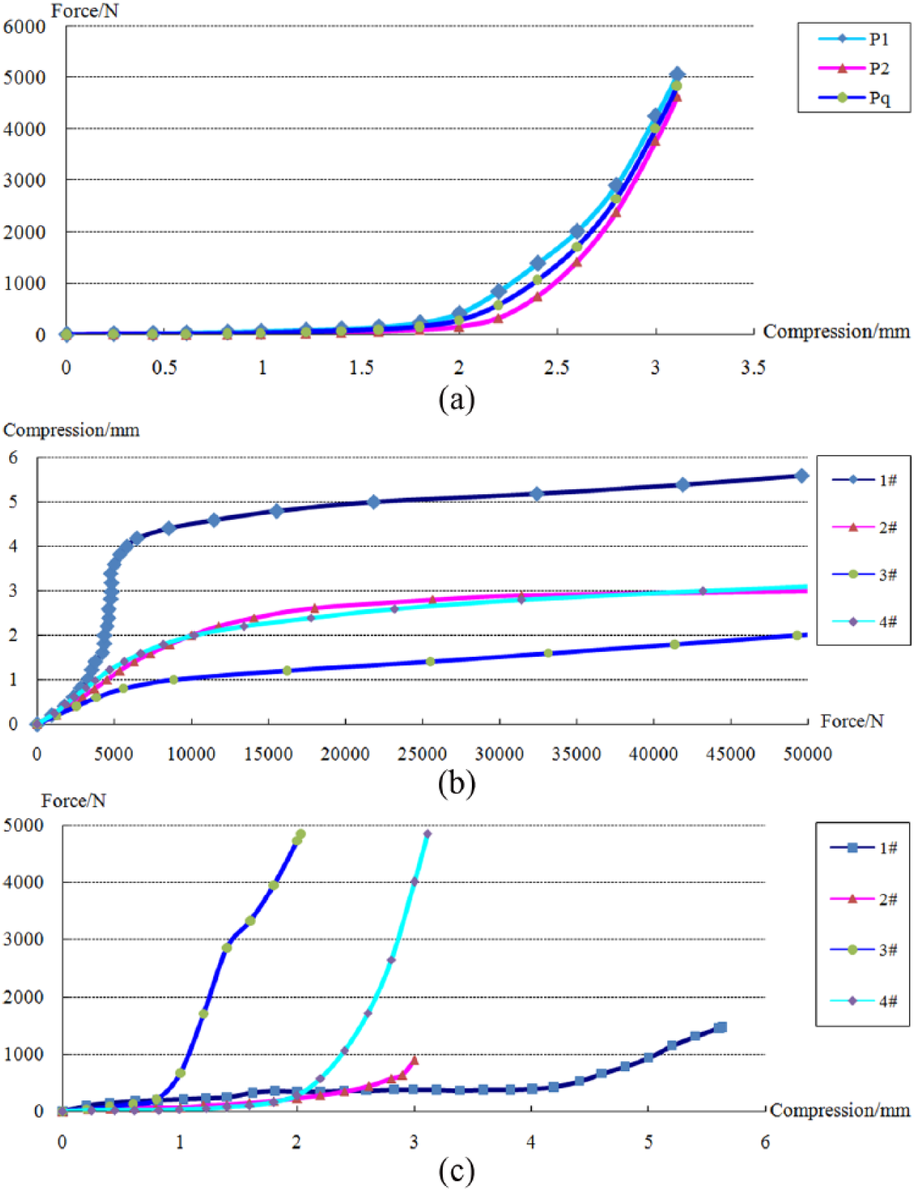
Results of mechanical property tests.
The performance curves of axial compressions changing with axial pressure are shown in Figure 3(b). The first specimen material is PTFE, with the hardness of the material itself being high. The axial compression amount is produced mainly through the deformation of the cross-section shape, so the outlet pressure initial axial compression is in a situation of significant and rapid change. For the same material of butyl rubber, the specimen axial pressure bearing capacity of the cycloidal section and “X” section is similar; the characteristics of the square section specimen are shown to be relatively harder.
Using the semi-ring method, the radial supporting force of every test piece can be measured, and the radial supporting force changing performance curve with the axial amount of compression is shown in Figure 3(c). In the first specimen, with the material PTFE, the axial compression amount is mainly caused by the deformation of cross-section shape, and radial expansion is very small. Therefore, the radial supporting force is visibly smaller. For the same material of butyl rubber, the test piece of square section and “X” section can generate a larger radial supporting force, but the cycloidal section shaped specimen radial supporting force is very small.
These results can be used to help select the material and section shape at the structure design stage. For example, if it is necessary to have anti-rotation and reduce vibration, a butyl rubber square section or “X” section should be chosen for its larger radial force, with the difference being that the axial compression amount of the “X” shaped section is larger.
Conclusions
A new method is proposed in this paper to measure the radial force of a supporting ring in mechanics performance tests. Compared with previous methods such as putting a hole in the circumferential direction by the support member to introduce a transfer bar, and fixing a thin layer of pressure sensor between the support member and the inner wall of the supporting ring, this method has the following advantages. The support ring and the contact condition of the inner wall of the support member are unchanged, thereby ensuring the authenticity of the force. In addition, problems concerning the leading measurement wire can be avoided.
This new method is applied in mechanics performance tests for PTFE and butyl rubber material for four kinds of section shape structure supporting rings. The results and analysis can be referenced for structure design.
Footnotes
Acknowledgements
The authors appreciate the valuable and constructive comments from the reviewers.
Declaration of Conflicting Interests
The author(s) declared no potential conflicts of interest with respect to the research, authorship, and/or publication of this article.
Funding
The author(s) disclosed receipt of the following financial support for the research, authorship, and/or publication of this article: This work was supported by the NSAF (grant number U1630120).