
Abstract
Introduction
DNA microarray technology has the potential to offer great benefits to those interested in genomics research and drug discovery. Applications for this technology include clone mapping, linkage analysis, highly multiplexed mutation detection, gene expression monitoring, and high throughput screening, among others. Although the value of microarray-based analysis is obvious, the technology for its use is still in its infancy.
The current state of the field has been nicely summarized elsewhere (Genome Research 7: 943–946; Nature Genetics 18: 195–197). Only a few laboratories have had significant experience with the technology, and standard protocols are lacking. The ability to obtain consistent results is clearly critical, Consistency is affected by a variety of factors including spotting instrumentation, surface characteristics and uniformity, efficiency of binding of spotted materials to surfaces, hybridization and wash conditions, and imaging systems. In order to study effectively all of the parameters which impact microarray analysis, there is a pressing need for broader access to open architecture systems.
The mechanism we have conceived and implemented to address these goals is based on surface tensions forces, and is described in detail below. Availability of an instrument based on this technology, along with an affordable high performance imaging system, will help drive the widespread use of microarray technology by individual investigators in genomics research and drug discovery. Moreover, as a general purpose tool, this instrument will find use in other fields such as cell biology, high throughput screening, and combinatorial chemistry.
Design concept
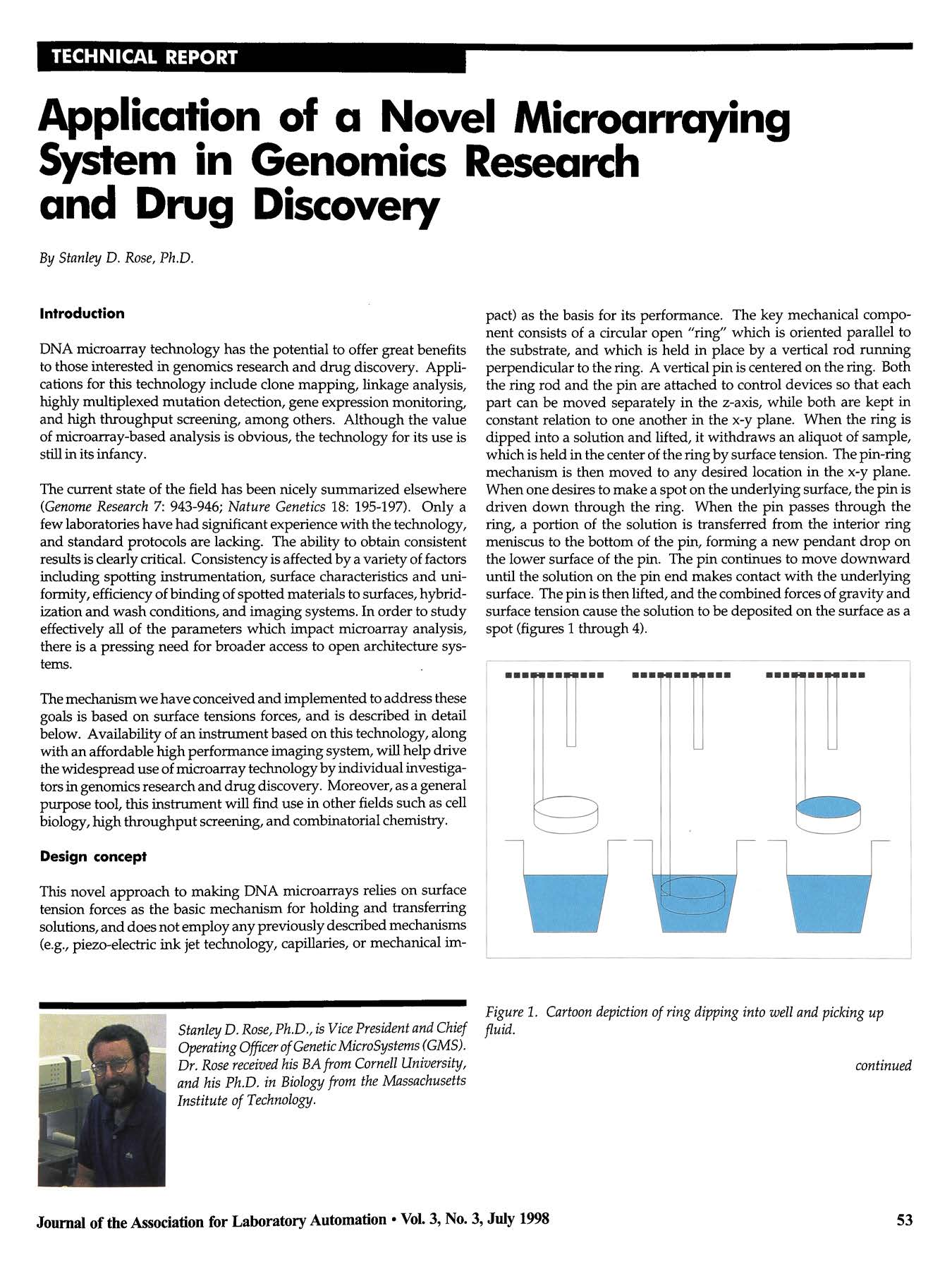
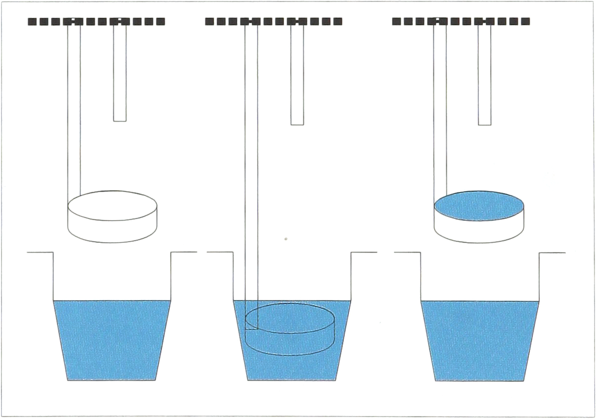
This novel approach to making DNA microarrays relies on surface tension forces as the basic mechanism for holding and transferring solutions, and does not employ any previously described mechanisms (e.g., piezo-electric ink jet technology, capillaries, or mechanical impact) as the basis for its performance. The key mechanical component consists of a circular open “ring” which is oriented parallel to the substrate, and which is held in place by a vertical rod running perpendicular to the ring. A vertical pin is centered on the ring. Both the ring rod and the pin are attached to control devices so that each part can be moved separately in the z-axis, while both are kept in constant relation to one another in the x-y plane. When the ring is dipped into a solution and lifted, it withdraws an aliquot of sample, which is held in the center of the ring by surface tension. The pin-ring mechanism is then moved to any desired location in the x-y plane. When one desires to make a spot on the underlying surface, the pin is driven down through the ring. When the pin passes through the ring, a portion of the solution is transferred from the interior ring meniscus to the bottom of the pin, forming a new pendant drop on the lower surface of the pin. The pin continues to move downward until the solution on the pin end makes contact with the underlying surface. The pin is then lifted, and the combined forces of gravity and surface tension cause the solution to be deposited on the surface as a spot (figures 1 through 4).
Cartoon depiction of ring dipping into well and picking up fluid.
Cartoon depiction of pin driving through ring, and transferring fluid spot onto a surface.
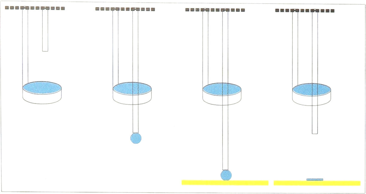
A single “pin-ring” mechanism, positioned over a 96-well microplate.
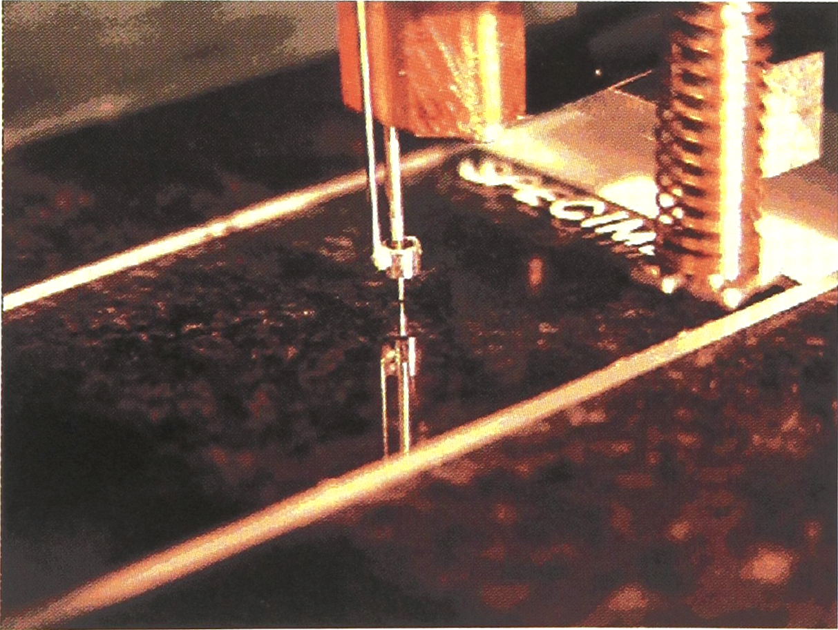
A single “pin-ring” mechanism, depositing a spot on a slide.
Neither impact nor mechanical contact between the pin and substrate are required for fluid transfer. Special mechanisms have been designed to achieve a balance between the need to rapidly move the pin in the z-axis, while at the same time minimizing the likelihood and extent of contact between the pin and the underlying surface. Movement of the pin through the ring's internal meniscus does not destroy the meniscus until enough aliquots of fluid have been removed such that some minimal volume threshold has been passed. Given the volumes present in the ring and on the pin, the pin driving process can be repeated many times, so that a very large number of similar spots can be created from a single moving ring. This consistency of spotting is perhaps the most important feature of the system. Rings currently in use hold approximately 1 μL, and the spots formed are estimated to be in the range of hundreds of picoliters. These rings are capable of lifting aliquots from wells containing less than 10 μL of sample.
Due to the open nature of this system, cleaning with solutions of water and alcohol, followed by air drying, is particularly effective. The ring is small enough to fit easily into the wells of either 96- or 384-well microplates. Spot size is dependent on pin dimensions, and thus can be controlled by available hardware. We have worked with spot sizes ranging from 50 to 300 micron in diameter. Fluid volumes transferred are roughly equal to the volume of a hemisphere with the radius of the pin (in the range of 50 pL to 5 nL, for pins used to date). The system appears to function well with a wide variety of fluid types, ranging from volatile organic solvents to viscous aqueous solutions. At least four pin-ring mechanisms can be operated independently or simultaneously on a single system, enabling spotting at a speed in excess of 4 spots per second. A 12 pin system has been developed in which all of the pins move in unison, providing greater speed at the expense of flexibility (i.e., giving up the ability to independently control each pin). A 48-pin system is currently being evaluated for ultra-high throughput, while maintaining consistency of spotting.
The “pin-ring” spotting mechanism has been incorporated into a fully-integrated arraying system consisting of an x-y robotic workstation which moves an adapter that currently is designed to hold as many as 4 pin-ring mechanisms (figure 5). The working platen includes space for 3 microplates (96 or 384 wells), a cleaning station (offering the option of a circulating water stream, a circulating alcohol stream, and a vacuum port), and 42 standard microscope slides. The system has been operated at a rate of 1 spot per second per pin, when spotting onto all 42 slides (this rate includes overhead time for cleaning). The 4-pin version will thus make arrays at a rate in excess of 4 spots per second. The system is controlled by a dedicated computer. A prototype Windows-based graphic user interface has been developed which enables the operator to easily program the instrument for parameters such as plate type, number of plates, number of wells within plates (if only a portion of a plate is to be spotted), number of replicate slides to spot, array density, location of array placement onto slides, and wash time. Results from recent experiments with this system are described below.
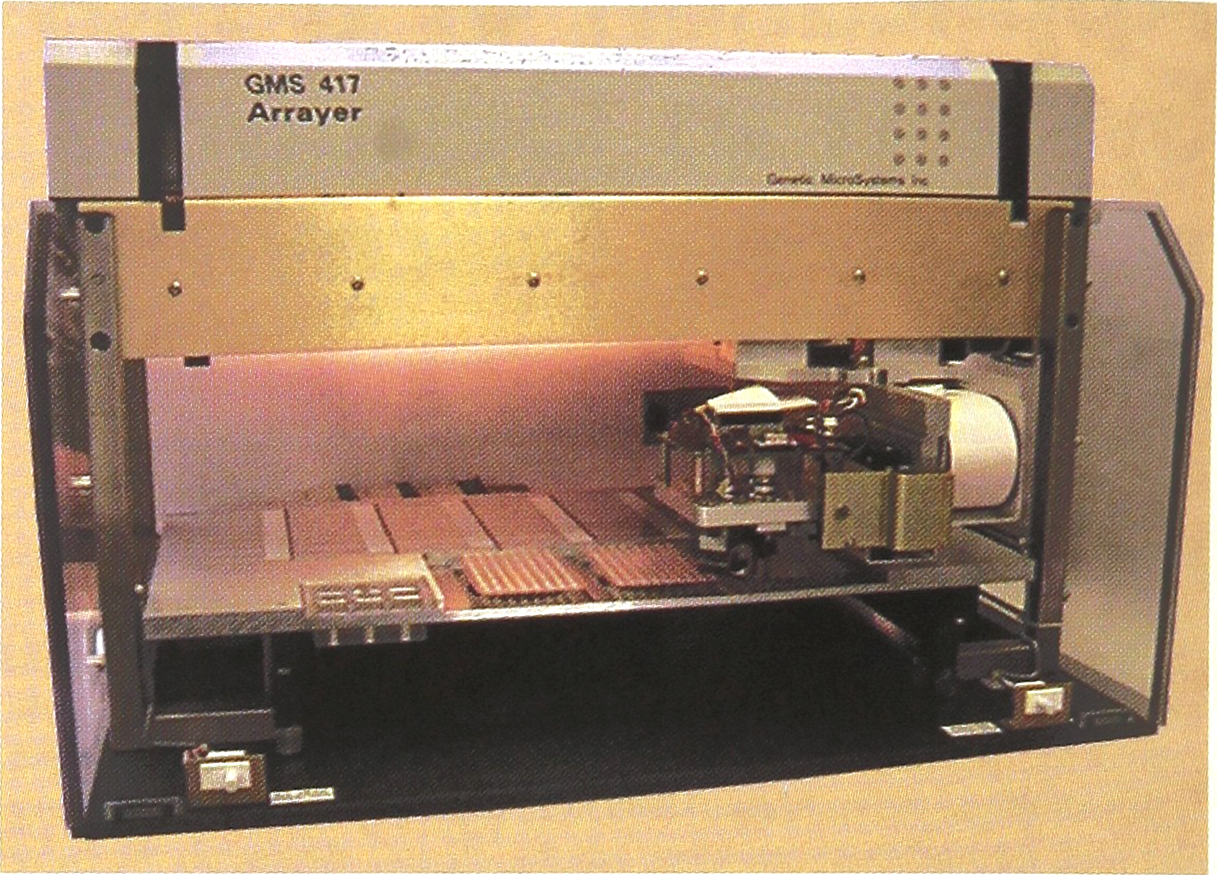
A prototype arraying instrument employing the “pin and ring” design.
Applications and Results
A simple model system was used that would allow us to obtain rapid results from relatively small arrays, without the use of complex scanning laser systems. Samples to be arrayed were 1:1 mixtures of a stock solution of anonymous plant DNA at a concentration of 500 ng/ μL, and a stock solution of eosin diluted 1:10 in 2x SSC. All the wells in each row of a 96-well polycarbonate “PCR plate” were each filled with 20 μL of various dilutions of this stock, as follows: A, B-stock; C, D −1:10 dilution; E, F-1:100 dilution; G, H-1:1000 dilution.
The eosin stain present at these concentrations can be seen with a fluorescent microscope equipped with a Mercury-Xenon lamp and a 532 run filter, so that performance could be assessed immediately. Slides were subsequently imaged with a scanning laser based system for presentation purposes. As can be seen in figure 6, spots produced with this system are very consistent in size and shape, as well as with respect to fluorescence intensity for each given dilution. Spot sizes were approximately 200 micron, and spots were place at 400 micron intervals, center-to-center.
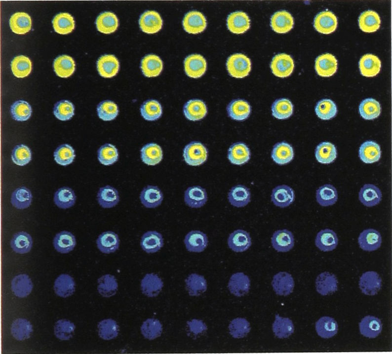
Portion of a typical array of serial dilutions of plant DNA stained with eosin.
A portion of a second array consisting of samples of plant DNA at five different concentrations, again stained with eosin, and randomly spotted, is displayed in figure 7. This array also contained spots of approximately 200 micron in diameter, placed at 400 micron intervals, center-to-center.
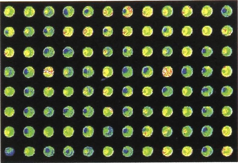
Portion of an array of samples of plant DNA, at 5 different concentrations, stained with eosin, and randomly spotted.
Discussion
Prior approaches to creating arrays can be roughly grouped into two categories: those involving in situ synthesis on a surface, and those involving placement of samples onto a surface.
The in situ synthesis, as developed by Affymetrix, is performed by a photolithographic process. The synthesis is slow and expensive, only becoming cost effective if very large numbers of identical chips can be manufactured. This approach involves the use of a service that can only be performed by the owner of the process, and requires a large up-front investment by the customer to create a specific array. As molecules are actually being synthesized, base by base, this procedure is limited to the creation of small nucleic acid fragments in any given spot on the array. Spot size is limited only by mask-making capabilities. Since spot density can be extremely high, this approach makes the most sense when the highest spot densities are required, and very large numbers of samples will be analyzed with the chips each carrying copies of the same array.
Spotting instruments we know of rely on either a) electrochemical reactions to attract negatively charged nucleic acids to particular locations on a sticky surface, b) capillary action to lift a sample into a tube, which is then expelled onto the surface, c) piezo-electric ink-jetting technology to draw a sample in from a reservoir and then “spritz” the sample onto a surface, d) precision micropipettes, and e) a quill-based system.
The electrochemical synthesis involves a very large up-front investment, and the use of complicated tools which cannot reasonably be made available to individual investigators. This approach has its greatest utility when lower density arrays are required. It is also more useful (compared with photolithographic synthesis) if longer DNA molecules are being used in the arrays.
The systems based on capillary action, quills and ink-jetting have been in development for many years without reaching wide commercial availability. It appears that a number of problems need to be resolved relating to the differences in size and shape of the spots which are placed (which can lead to differences in resulting signal intensity or overlap of spots), “missed spots” (where little or no sample is placed on the surface), and the overhead associated with cleaning and reloading. Minimal spot size with both of these approaches is a function of the working volumes of solutions that can be lifted and spotted. Array density is related to the spot size, as well as the capabilities of the x-y positioning mechanisms employed.
Thanks to the efforts of the Brown Lab (Stanford), the information required to make and use quill based spotters is available freely over the World Wide Web (http://cmgm.stanford.edu.pbrown) This system will cost $25 – $40,000 in parts and the cost, time and knowledge to build and debug the system. Commercially available instrumentation is either much more costly or more limited in flexibility and performance.
The most compelling feature of the Genetic MicroSystems arraying instrument is the consistency of spots which it creates. By virtue of design, spots made with this instrument have a high likelihood of being very consistent in size. Other attractive features of this unit include its speed, which at 1 spot per second per pin is competitive with other systems, and its unique degree of flexibility. Examples of the flexible nature of the system include the following: can use 1 to 4 independently activated spotting pins; can use 12 pins with simultaneous spotting (with 48 pin/ 384 well system currently in development); can control spot size, from 50 μm to 300 μm, through a simple hardware change; can control spot density with software; the entire slide surface is available for spotting, with the user determining where to place arrays; soft spotting enables use of coverslips, filters or alternative materials; long thin pins enables arraying on bottom of microwells; offers the ability to place different fluids in the same spot; offers the ability to “multi-spot” (to put more material in same spot).
Conclusion
A novel technology for creating DNA microarrays has been described which is based primarily on surface tension forces. The performance of a prototype automated system which utilizes this technology has been demonstrated. In terms of speed of spotting, performance of this system is comparable to that which can be achieved with other more costly instruments. In terms of consistency, this system offers superior performance. The use of an inherently gentle force to transfer fluids from pins to surfaces implies a long lifetime and high reliability. In fact, the original “proof-of-principle” instrument has been running in our laboratories for more than six months without a mechanical failure in the spotting mechanism. Other features of the system, such as interchangeable pins of different diameter, and software selection of array density, are intended to provide a unique degree of flexibility and ease of use in a versatile instrument designed for many different uses by individual investigators. The availability of an affordable, high performance arrayer will facilitate more widespread use of DNA microarray technology.
Footnotes
Acknowledgments
The author thanks David Bradbury, Wilfried Eggers, Peter Rowers, David Fullerton, Peter Honkanen, Wei Min Honkanen, Sokom Kim, Myles Mace, Jr., Greg McGuinness, Jean Montagu, Jeff Muller, Jim Overbeck, Frank Pagliughi, Jessica Pettit, Guy Praria, Bob Schenk, Tim Woolaver, Hub Yonkers, all of Genetic MicroSystems, whose hard work and dedication has made this publication possible. The author also thanks Elise Rose and Vivian Cheung for their comments, discussions, advice and assistance.