
Abstract
The release profile of active pharmaceutical ingredient (API) from its solid dosage form is an important aspect of drug development as it is often used to predict potential drug release characteristics of a product in vivo. In recent years, magnetic resonance imaging has emerged as a nondestructive technique that captures the physical changes of solid dosage forms during dissolution. An example that highlights this application is in the dissolution of modified-release tablet studies. As the tablet dissolves, API disperses in a hydrogel matrix within the tablet, and swelling of the hydrogel layer eventually leads to release of API over time. To achieve optimum signal-to-noise ratios, the tablet should be placed in the most homogeneous region of the magnet and remain there throughout the dissolution experiment. Moreover, the tablet holder must maintain the tablet position without interfering with the natural dissolution process, such as by crushing the softened tablet. This can be difficult because the size, shape, and rigidity of the tablet change during dissolution. This article describes the process, material, and manufacture of a novel device that meets these challenges, with emphasis on how additive manufacturing on a 3D printer enabled an efficient and inexpensive process of design improvements.
Keywords
Understanding the release of the active pharmaceutical ingredient (API) from a solid dosage form is important in ensuring the safety and efficacy of a drug. The most well-known in vitro experiment to determine the drug release profile is referred to as dissolution. Dissolution experiments are performed using specialized vessels, where tablets are submerged in a medium that is representative of the gastrointestinal tract. Aliquots of the dissolution medium are sampled at different time points, and the concentrations of the API in these solutions are determined by UV-Vis spectroscopy.1,2 Although the industry relies on dissolution experiments as a means of quality control and to predict bioavailability, the dissolution setup does not lend itself toward understanding the physical changes in the tablet while it dissolves. Although video or still images of the tablet can be captured during a dissolution experiment, inner structures cannot be probed unless the dissolution experiment is stopped and the tablet is sliced open.2,3
Magnetic resonance imaging (MRI) provides a noninvasive way to study physical changes of the tablet in real-time. This technique is well known for in vivo imaging, which differentiates types of tissues as a function of signal from hydrogen atoms (e.g., in water or fat).2–5 We used MRI to study water diffusion into modified-release (MR) tablets. The key element of the type of MR tablet we chose to test is the formation of an outer hydrogel layer when exposed to dissolution medium. 6 The thickness of the layer increases with time, and it determines the rate of API released. Characteristics of this release mechanism during the time course of an imaging experiment include tablet expansion during the formation of hydrogel layer, dissolution (thus a reduction in size), or a combination of both. The dissolution process and thus the time course of the imaging experiment can span several hours.
A variety of techniques have been described for tablet placement during dissolution experiments. Shiko et al. 7 performed dissolution studies carried out with the use of direct tablet placement on glass beads. Abrahmsén-Alami et al. 8 used a water-permeable glue to attach the tablet to a rotating disc. Butler and Nott 9 provided three types of designs in their study in which a snap ring was used to place the holder in the sample container, and the holder was a retaining band, plastic hook, or adhesive. Our aim was to produce a holder of a single universal design that could work effectively for tablets with a wide variety of properties, including different shapes and API release profiles. We thus created a holder that eliminates the need for adhesive and, instead of static plastic hooks that may impinge on the tablet as it swells, we use flexible compressed springs that can change dynamically as the tablet dissolves. Foremost, our tablet holder can actively maintain the tablet’s center point position. This design feature enables optimal signal-to-noise ratios during MRI analysis, as good images require the tablet to be positioned at the most homogeneous part of the magnetic field within the instrument and remain there during the time course of each experiment. 5 To validate and demonstrate the utility of our novel holder for MRI tablet dissolution studies, MRI images of an MR tablet were obtained during field testing using the final product.
Materials and Methods
Design Concept
The tablet holder is designed to be used in conjunction with a standard 50 mL Corning polypropylene sterile centrifuge tube that houses the tablet ( Fig. 1 ). The tube is then mounted in a sleeve known as a resonator, where signal detection occurs. The resonator and probe assembly are placed into position from the bottom of the MR magnet and secured into its fixed position ( Fig. 2 shows the different parts of the instrument, which are described in the Field Testing section). Therefore, the most basic purpose of the holder is to secure the tablet at the same position within the instrument to ensure reproducibility. In addition, the holder should allow for size changes of the tablet during dissolution. To achieve this, two mechanisms working in conjunction with one another are required: a clip (or fixed) portion that would secure the tablet at a predetermined height within the sample containment vessel and an active support section (or compressed springs) that can respond to tablet’s changes during the dissolution process, expanding and contracting with the tablet. Top and bottom holders are used for each experiment. The distance between the two parts is adjusted such that the tablet is lightly cradled between compression springs, allowing for swelling and dissolving of the tablet while still maintaining its reference position. Each holder is secured to the sides of the tube with a snap ring design, inspired by Butler and Nott, 9 which makes up the fixed portion of the holders. The spacer tail appendage provides a reference position from the bottom of the tube (see Fig. 1 ).
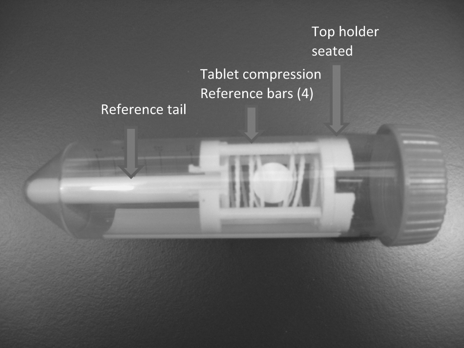
Tablet mounted between top and bottom holders in a 50 mL Corning tube.
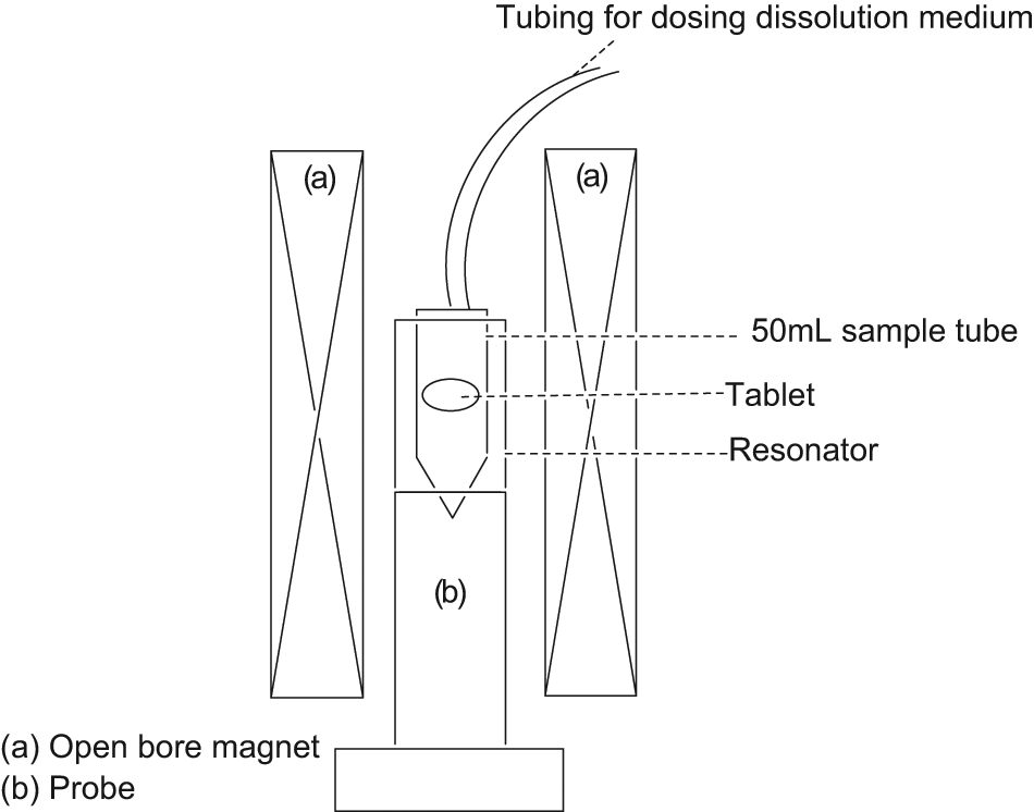
Scheme of the magnetic resonance imaging instrument showing the position of the tablet with respect to the probe and the magnet. Note that the magnet is open-bore, allowing access to the tubing for dosing dissolution medium.
Identifying the optimal spring force that could be exerted on the tablets to secure them, while simultaneously allowing changes in the tablet size and shape during dissolution, required multiple rounds of development improvements. Additive manufacturing facilitated this process; small adjustments to the springs, such as pitch, free length, helix, number of active coils, and coil diameters could be modified and tested within a single day. The load on the springs was adjusted by the distance between the top and bottom clips, once the optimal combination was determined; the fixed spacers were added to the bottom holder to provide repeatability. This design does not require any form of adhesive to hold the tablet in position; only a light opposing force from two sides is required. To minimize signal interference, the tablet holder should not obstruct the view of the tablet’s profile of interest.
Materials
The strong magnetic fields used in MRI imposed certain limitations in terms of the appropriate materials we could use to build our holder.2,10,11 For example, ferromagnetic material is not an option, and diamagnetic metals would be cost prohibitive to manufacture, even if it were possible to build them to the same standards each time. Finding the perfect spring expansion and compression strength required numerous attempts that could be proven only by actual physical testing, and the time and cost of doing this with conventional manufacturing techniques prevented this testing from being a viable option. We thus used the SolidWorks 3D solid modeling CAD program to facilitate our design process. Fused deposition modeling (FDM Technology), which is an additive manufacturing process performed on a uPrint rapid prototype system, addressed the issue of manufacturability and material suitability.12,13 The uPrint uses two materials when building a part: a soluble support material that supports the subsequent layers during the build process along with the build material, which is an ABSplus (acrylonitrile butadiene styrene) thermoplastic that makes up the final part. The plus indicates that the ABS has some preparatory additives used to promote layer adhesion.
Method
The FDM Technology uses ABSplus modeling material and soluble support material fed from autoloading carriers in the material bays up to the print head. The materials are then heated to a semi-liquid state, fed through dual extrusion tips, and precisely deposited onto the modeling base in extremely fine layers. The print head moves in X-Y coordinates, and the modeling base moves down in the Z-axis as the model and its support material are built from the bottom up, layer by layer. After the build is complete, the support material is dissolved away, and the part is ready to use. 12 Figures 3 and 4 show the tablet holder assemblies before and after the support material was removed. Requirements that the holder be hydrophobic, nonmagnetic, easily manufactured, and reproducible were fully met using this technology.
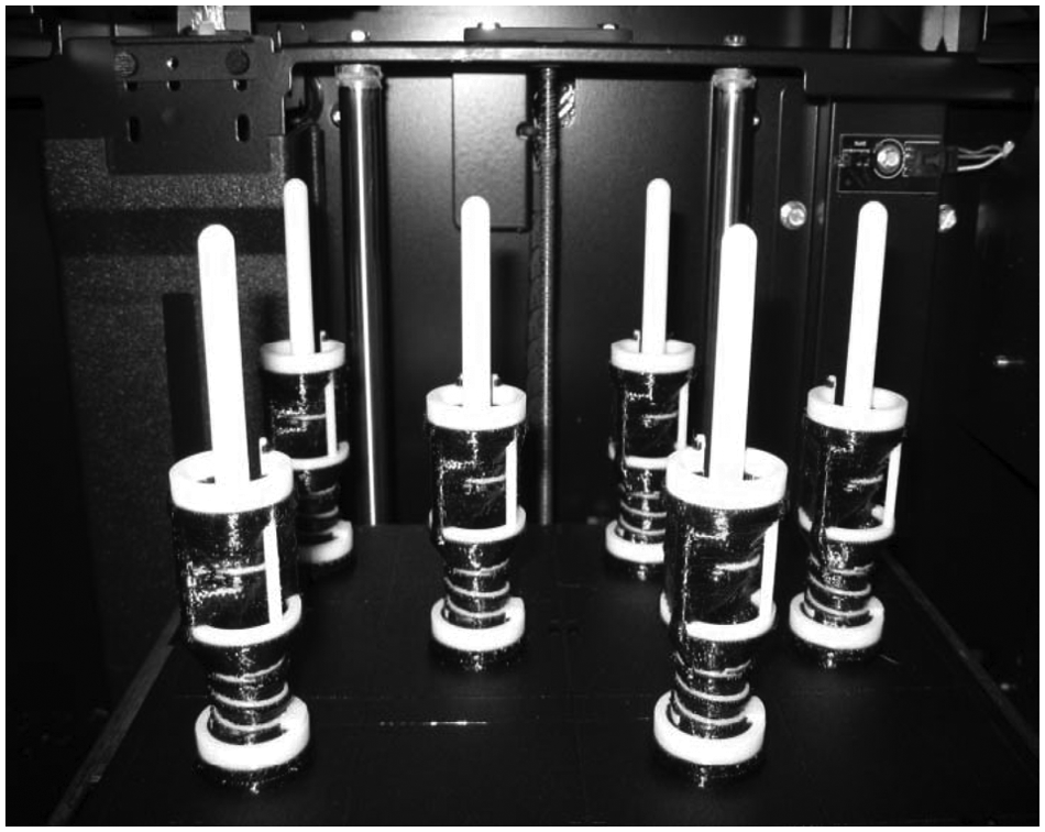
Tablet holder assemblies after overnight build on the uPrint. Top and bottom holders were built as assemblies for demonstration purposes.
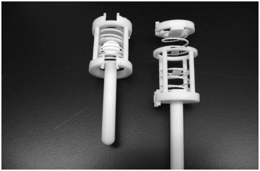
Assemblies after support material removal and with tablet installed.
Field Testing
The scheme of the tablet holder within the MRI instrument is as follows. The sample tube fits within the resonator, which is the part of the MR probe used for signal detection. The probe is placed inside a vertical open-bore magnet such that the top of the sample tube can be accessed through the top of the magnet (refer to Fig. 2 ). Preacquisition steps of probe tuning and shimming were performed using a sample tube filled with dissolution medium of sodium dodecyl sulfate solution at pH 6.8 dosed with Magnetvist to reduce wait time in between signal acquisition. Once the preacquisition steps were completed, the tube of dissolution medium was replaced with a tube containing the tablet mounted in its holder without any dissolution medium. Image acquisition was commenced simultaneously as the dissolution medium was dosed through tubing connected to the top of the sample tube. Images were acquired using the spin-echo pulse sequence performed on a Bruker spectrometer, equipped with an Ultrashield 500WB magnet (proton resonance frequency = 500 MHz, 89 mm bore size) and a micro 5 imaging probe. To accommodate for the rate of gel formation, images were acquired every 2 min.
Results
To accomplish our goal of developing a universal tablet holder for MRI dissolution studies, two criteria had to be met in field testing. We needed to confirm that the tablet holder did not interfere with the physical changes of the swelling tablet, and more importantly, we had to demonstrate that the presence of the holder’s ABS material in close proximity to the sample did not create any image interference in terms of the MRI signal. In our case, the MRI signal is due to the presence of hydrogen in water molecules; thus, the brightness of each pixel is a function of water concentration. Regions with no water should be dark; Figure 5 shows cross sections of two images of the tablet at 2 min and 16 h in dissolution medium. The dark region in the middle of the first image is the solid tablet with no water penetration. The cross section of the tablet holder is also dark, showing the springs and the cradle holding the tablet. We demonstrated that the holder did not physically interfere with tablet and that the quality of the images is not compromised by the presence of the ABS on the tablet by introducing artifacts. Figure 6 shows a more quantitative view of the results. The signal intensity in a region of interest was plotted with respect to time from t = 2 min to t = 120 min of the total dissolution process. The region chosen was at the interface of the tablet and dissolution medium. This is a dynamic region where there is no water intrusion into the tablet and a gel layer is formed. The image at t = 2 min shows a clear boundary between the dry polymer core, which is the initial state of the tablet, and the dissolution medium. As the tablet was exposed to the dissolution medium, a decrease in water content was observed at this boundary region. This is due to the formation of a diffusion front eventually leading to a clear gel layer as the dissolution medium interacts with the polymer. This decrease was measured quantitatively over 2 h. As shown in the graph, we observed a monotonic decrease in water signal, indicating that the tablet is swelling, displacing more water from the region of interest. The quantitative plot underpins that the images are of good quality and free from interference.
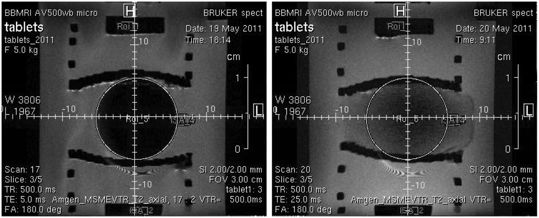
Cross section of tablet at time = 2 min and time = 16 h. Brightness corresponds to water concentration; dark regions correspond to absence of water signal.
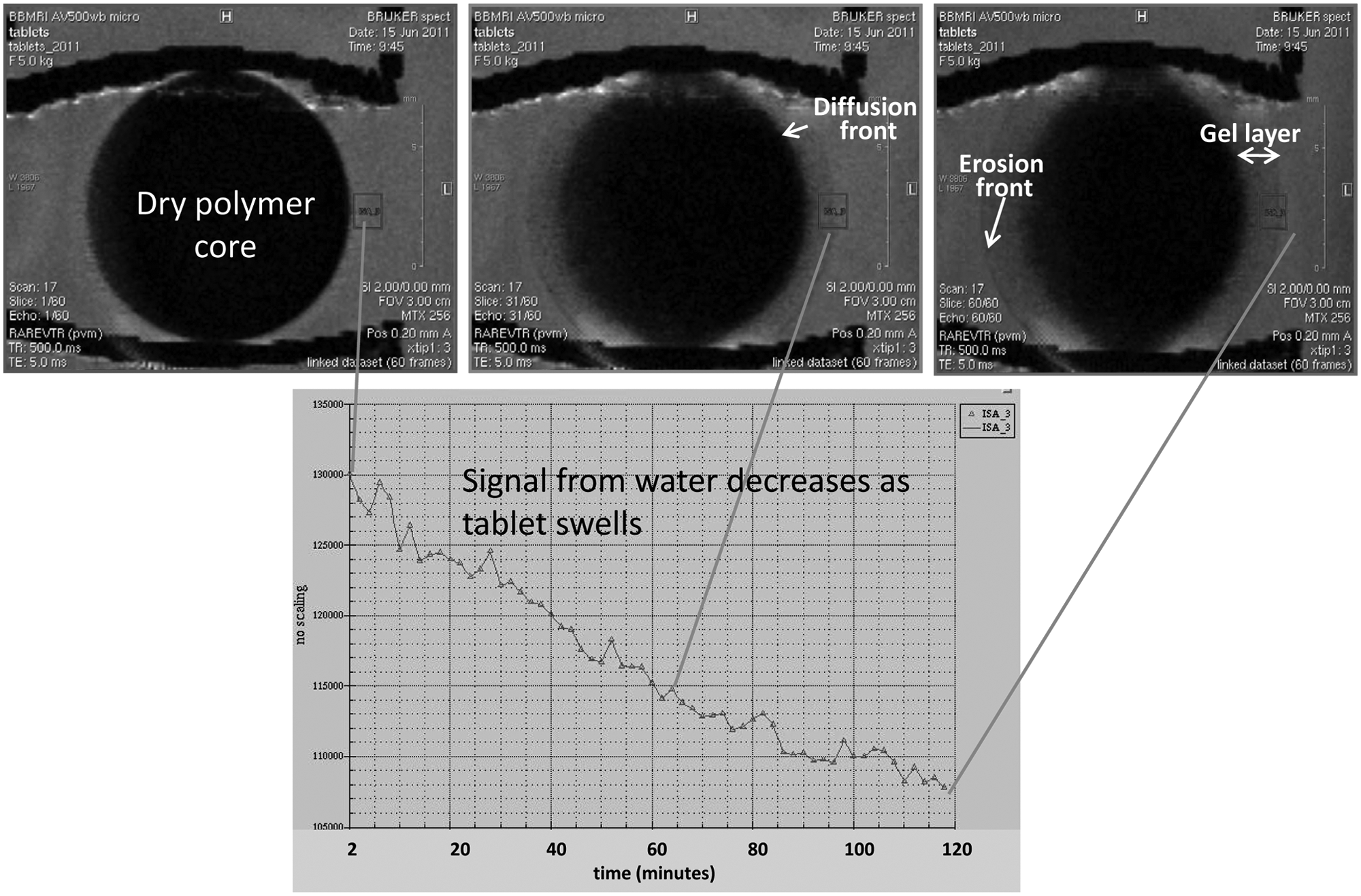
Signal intensity from water in a specified region of interest (marked by the green rectangle) with respect to time during the first 2 h of dissolution.
Conclusions
We have identified fused deposition modeling using ABS as a suitable manufacturing method and appropriate working material that met all of our requirements for a tablet holder compatible with MRI. Images of an MR tablet exposed to dissolution medium were obtained during field testing. Formation of a gel layer was followed by quantitative water concentration measured over a period of 2 h. These results demonstrated that the presence of ABS did not cause any interference to the tablet images. In addition, the design was able to accommodate for the changing size and texture of the tablet during dissolution. We plan to implement continuous flow of dissolution fluid during imaging. This will allow us to employ a T-junction to sample the dissolution medium at different time points. These samples can be analyzed for API concentration using more traditional offline techniques such as UV-vis spectroscopy, allowing us to gain a more holistic understanding of the solid dosage form of interest.1,2
Parts made of thermoplastic material are often not durable enough to hold up as finished parts and are more suitable for conceptual renderings, serving to prove fit, form, and function. 12 However, in this work, the use of thermoplastic material in the final product was beneficial because of its compatibility with MRI analysis. The ability to prototype and test designs quickly and inexpensively promotes further innovation and improvement. More importantly, this basic design can be modified to accommodate for changing criteria that may arise from different tablet types, shapes, and dissolution rates.
Footnotes
Acknowledgements
We thank Saaussan Madi at Bruker Biospin (Billerica, MA) for providing instrument time for field testing and MRI expertise. We acknowledge Violeta Yu of Amgen for her careful review of the article and Craig Schulz of Amgen for his support on this project.
Declaration of Conflicting Interests
The authors declared no potential conflicts of interest with respect to the research, authorship, and/or publication of this article.
Funding
The authors received no financial support for the research, authorship, and/or publication of this article.