
Abstract
Many of the therapies for personalized medicine have few dosage options, and the successful translation of these therapies to the clinic is significantly dependent on the drug/formulation delivery platform. We have developed a lab-scale integrated system for microdosing of drug formulations with high accuracy and precision that is capable of feedback control. The designed modular drug dispensing system includes a microdispensing valve unit and is fully automated with a LabVIEW-controlled computer interface. The designed system is capable of dispensing drug droplets with volumes ranging from nanoliters to microliters with high accuracy (relative standard deviation <1%). We have determined that the system is capable of accurate dosing and in-line real-time gravimetric control.
Introduction
Precise dosage formulation is a key component of controlled drug delivery that permits enhanced control and prediction of the diffusion rate of the drug out of the carrier system and into the targeted area for therapeutic application. Unfortunately, these designs are usually complex and involve large-scale manufacturing processing to obtain the resultant drug delivery system. One of the most promising and forward-thinking technologies that can be employed in the design of controlled-release delivery and precise dosage formulations for small-scale manufacturing systems is drop-on-demand (DoD) technology.
Presently, in drug development, most automated liquid handling tasks are accomplished via displacement-type devices that use a syringe/plunger coupled to a metal or plastic tip. 1 Typically, these devices can dispense over the range of microliters to milliliters. As an interim solution to provide dispensing, syringe pipettes can be configured to produce a small drop on the tip that can be touched to a dry surface for dispensing (touch-off dispensing).
In the past decade, various microfluidic systems have been developed that address the problem of dispensing nanoliter to picoliter quantities of different kinds of fluids. Some of them are quite similar to inkjet print heads and use DoD technology for ejecting single liquid droplets in the nanoliter range.
A broad range of diverse technologies fall into the DoD category. The physics and the methods employed within this group may differ substantially, but the end result is consistent generation of small droplets of fluid. 2 Authors identified three types of distinct methods that can collectively be classified as inkjet printing. These methods include deposition of drop via continuous inkjet (CIJ) or DoD printing. CIJ printing entails the continuous printing of droplets, and DoD indicates that droplets are only printed as needed (i.e., on demand). DoD printing can be done using thermal inkjet (TIJ), piezo, or bubble jet. 3 In CIJ, the liquid stream jet is broken up in the presence of external forces to generate droplets of equal and size and to retard or suppress the formation of satellite droplets. 2 Piezo-type DoD works by the utilization of a glass capillary tube connected to a piezoelectric transducer or attachment of sleeve. Application of a negative or positive voltage will cause the capillary tube to expand or contract, respectively. Droplet generation can be achieved by the application of appropriate waveforms; however, precise application of this method involves vast amounts of experimentation to determine the ideal values of waveform parameters to deter the formation of satellite drops. 2
Most all drug development activities that employ the DoD/inkjet printing approach involve similar principles but with some modifications specific to the desired application. In general, a bio-ink, macromolecule, or drug is loaded into a cartridge of an inkjet printer, and the drug is released in a controlled manner via thermal, piezoelectric, or pressure means. Inkjet technology has proven to be useful in the pattern formation and printing of cells, DNA arrays, microchips, and other biomaterials; transdermal delivery; and precision dosing of drugs.4,5 In addition, the ability of inkjet printing to maintain control over spatial parameters while printing 2- and 3D structures indicates that it has great potential toward advanced tissue engineering applications such as organ printing. 6 Even greater opportunities exist for inkjet printing of controlled drug delivery systems and precision dosing. 7 Research has shown that inkjet printing has the potential to increase efficiency and bioavailability, as well as decrease overall waste8,9 of pharmaceutical compounds. The use of inkjet dispensing technology generally provides several advantages over syringe pump-based liquid handling. As a noncontact printing process, the volumetric accuracy of inkjet dispensing is not affected by how the fluid wets a substrate, as is the case when positive displacement or pin transfer systems “touch off” the fluid onto the substrate during the dispensing event. 10 In addition, the fluid source cannot be contaminated by the substrate, as is the potential during pin transfer touching. In addition, as for a noncontact printing, delivery of the drop to a small location is not limited by the mechanical size of the tip. The ability to free fly the droplets of fluid over a millimeter of more allows fluids to be dispensed into wells or other substrate features (e.g., features that are created to control wetting and spreading).
In this article, we present a newly developed lab-scale modular system for a microdosing application of pharmaceutically relevant compounds. Using DoD technology, the developed system allows small-scale fabrication of unit dosages with high accuracy and flexibility. The system is linearly scalable by the addition of a number of microdosing units.
Several material properties such as surface tension, viscosity, and elasticity have been shown to affect the printing performance on inkjet inks. 11 The fluid dynamics involved in drop formation and spreading plays an important role in colloidal ink design. Successful drop formation occurs when the ratio Re/We has a value between 1 and 1012:

where
In inkjet printing, droplets are formed from the breakup of liquid jets by surface tension. These jets and droplets are formed at extremely high speeds with the liquids experiencing very high shear rates. The fluids often contain significant amounts of polymer and/or particulates and so have complex rheological properties under these conditions.
The main research needs in realization of this approach are to modify existing small-scale microdosing equipment to include the DoD capabilities, and formulation materials need to be researched to create formulation platforms that can be used to generate small numbers of product units with precisely controlled in vivo performance. Important technology requirements for the DoD system include the following (see also Fig. 1 ):
ability to predict the desired formulation for active pharmaceutical ingredients (APIs) to achieve desired drop formation and solidification;
ability to predict optimum conditions required to form drops with specific size required by dosage performance targets;
accurate prediction of droplet impact, spreading phenomena, adhesion, and drug penetration;
understanding and control of the final microstructure and stability of the splat;
real-time process management capability.
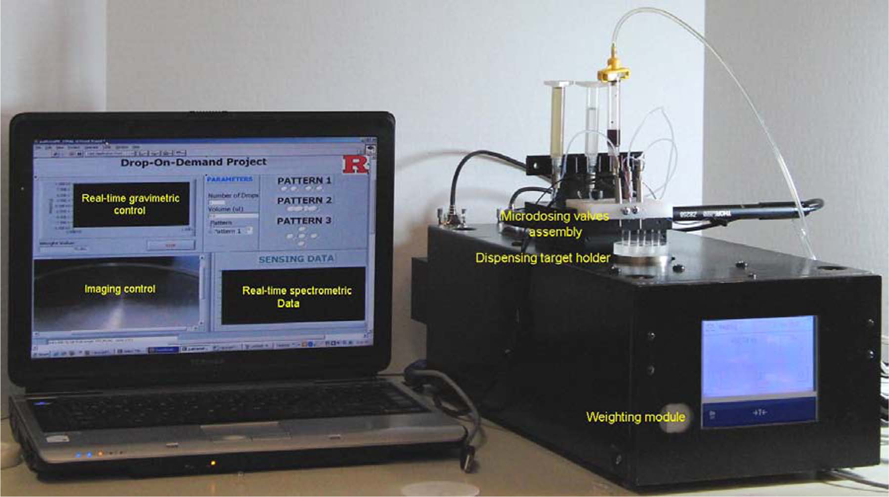
Overall automated drop-on-demand system with real-time gravimetric control design and key elements.
Experimental Details: DoD System Design and Integration
Mechanical Design
The dispensing system consists of a pressurized fluid reservoir, which is connected to a pressure-regulated gas source using a barrel adapter assembly and to the VHS microdispensing unit (The Lee Company, Westbrook, CT). The microdosing valve is computer controlled via a driver module that provides an operating voltage by converting a transitor-transitor logic (TTL) control signal into a spike and hold voltages that can be used to generate droplets. The initial voltage spike is necessary to decrease valve-opening time but too high for continuous operation and therefore must be reduced after the valve has been actuated. The TTL signal is generated via a digital port on the digital input/output card (National Instruments, Austin, TX). The system is operated via a LabVIEW-controlled computer interface. The gas inside the reservoir pushes the solution out through the dispensing valve when it is in an open position.
There are three ways the dispensed volume can be changed:
Interchangeable dispensing nozzle
Input pressure that directly affects the volume dispensed
Precise control of valve-opening time
All of these variables can be adjusted to find the best dispensing conditions for a specific fluid. Figure 2 shows a schematic of a DoD inkjet system.
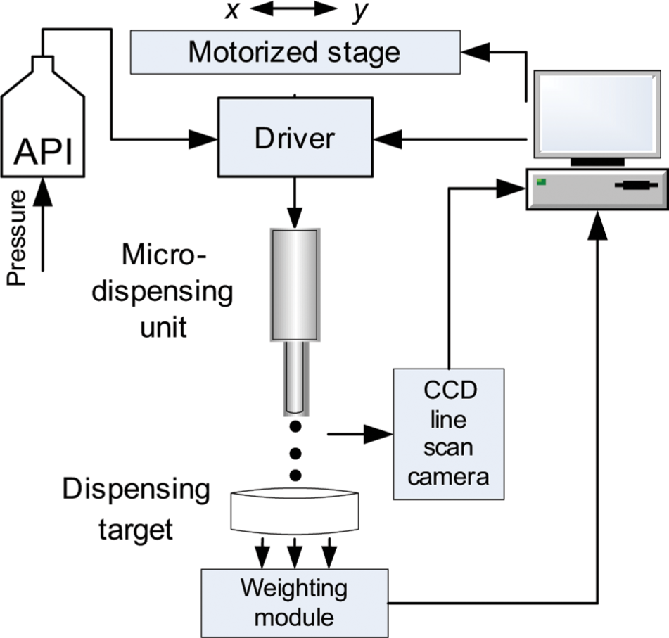
Schematics of a drop-on-demand microdispensing system. API, active pharmaceutical ingredient.
Located beneath the valve, a weighting module (WM; WXSS205DU; Mettler, Toledo, OH) interfaces with a PC for automated weight recording and real-time gravimetric control. Installed line-scan camera (not shown) allows automated image acquisition and control of the process. The weighting module and dispensing system may be placed inside an enclosure for better control of the environment and overall microdosing process performance.
Weight Measurement
The gravimetric control program module configures WM, controls the measurement process, and continuously takes dynamic weight measurement every 250 ms until the programmatic or user-initiated end of process. The user-defined input parameters are environment, measurement release, and auto-zeroing. Measurement release specifies how fast the balance will consider the measured value as stable. The repeatability of the measurement is lower with a higher speed of measurement. Environment specifies the stability of the surroundings with respect to temperature fluctuations and vibration. Auto-zeroing zeroes the scale before every measurement. The weighting module has control over the RS232 serial port. Once the serial port has been called, it configures to function with the weighting module and opens the port for communication using the Virtual Instrument Software Architecture (VISA) command. Later, a sequence of commands pertaining to the measurement setup, as defined by the user, is sent to the module. Finally, the measured weight is read as an array and stored in a user-specified worksheet.
The system can be operated in two modes. In the filling mode, the fluid ejected by the valve is collected into a small container (capsule, vial, syringes, etc.) mimicking the operation of the filling or compounding equipment at small dispensaries or labs. The container is placed into a plastic holder that is mounted on the top of the weighting module. As the API formulation is ejected based on user-defined settings of pressure and valve-opening time (τ), the actual mass of dispensed drug is measured and recorded in real time. In the printing mode, the fluid is ejected in single droplet form and is deposited (i.e., “printed”) on a target substrate (films, tablets, etc.). The system parameters such as opening time of valve, printed pattern, and pressure are manipulated to obtain printed drops of drug solution of desired quality. Using the weighting module, the actual mass of the droplet can also be monitored in real time.
Software Design
The measuring process is fully automated by the data acquisition and experiment control program. Developed GUI allows full control over unit dosage processing. Software schematics and data flow are depicted in Figure 3 . The control software was developed using LabVIEW G-Language. The program consists of three modules: valve control, weight measurement, and motion control.
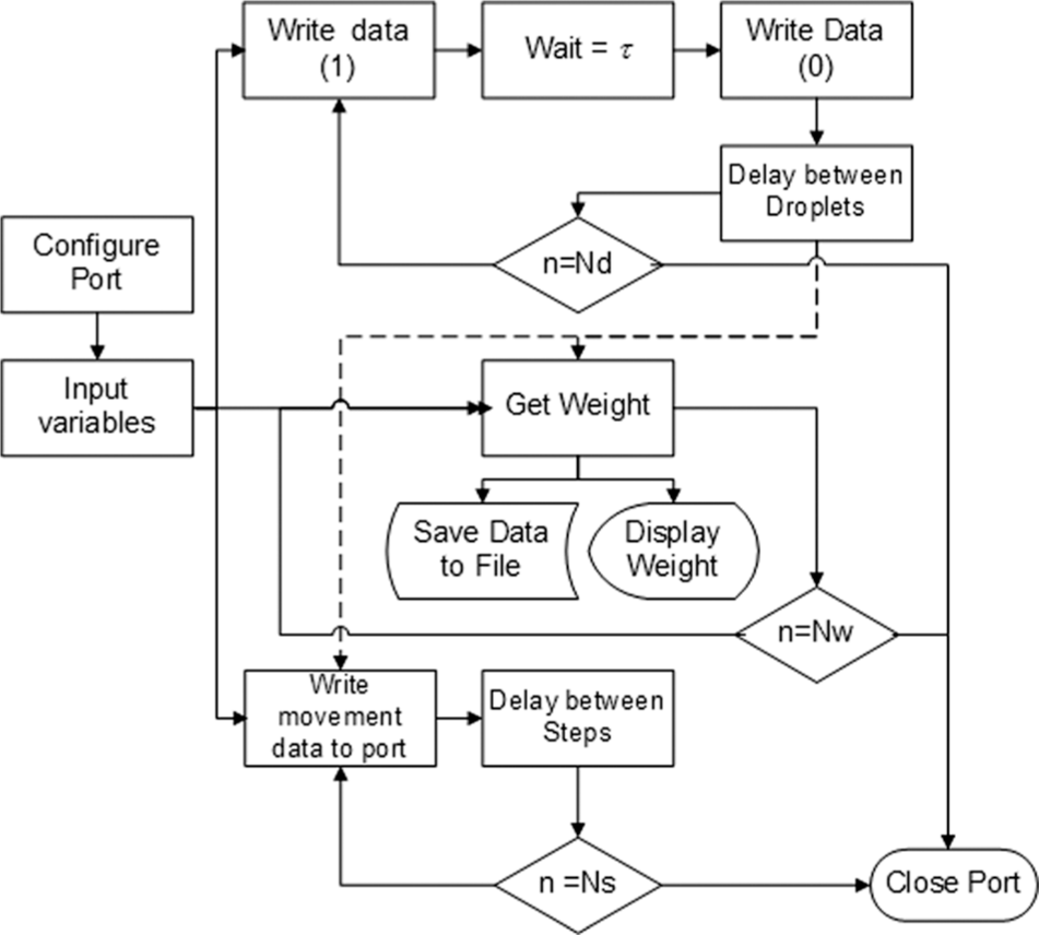
Control software and data flow block diagram.
Driving Waveform and Dispensing Valve Control
Precise control of signal waveform is required to produce accurate volumes of dispensed fluid. The driver module converts a TTL control signal into complex input waveform. The valve requires a short burst of power for actuate dispensing process, reducing its response time. Duration of initial high-voltage spike can be tuned 1.5 ms, and it is set to 2 ms. After the valve has opened, the voltage must be reduced to its minimal value sufficient for coil operation but to prevent its permanent damage due to generated Joule heat. Once the TTL control signal ends (value “0” on digital port output), the hold voltage is removed and the valve closes. Typical voltage waveform for the dispensing of single droplet is shown in Figure 4 .
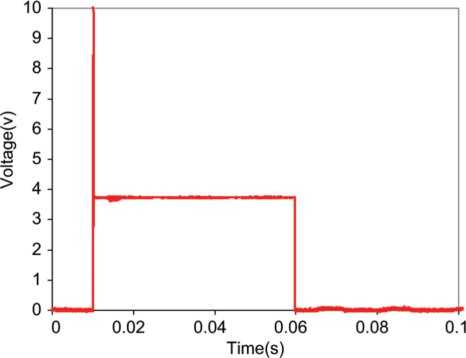
Acquired time history of voltage signal used to dispense droplets of various mass.
Pulse Generation for Multidroplet Continuous Operation
The valve needs to be opened and then closed within a set period of time. The system allows a set of user-defined variables such as “Pulse Duration” and “Number of Droplets.” When the task is initialized, it opens a loop that encloses all parts of a program that opens and closes the valve a specified number of times, with a delay for the motion control execution if necessary. This dynamic structure is represented by two parts: first, it generates a digital pulse, and second, it attaches an “on/off” signal to this pulse and sends it to the valve. To address a specific line on the port, we create a virtual channel, adding it to a task. The instances of this block correspond to the input/output (I/O) type of the channel, such as analog input, digital output, or counter output. In this instance, the block creates a channel to generate digital pulses that frequency defines. Because the valve opening and closing need to be very accurate, a hardware clock is used to time these pulses, and its address is supplied as input to the block. DAQmx Start transitions the task to the running state to begin the generation. This block is required because data are written to the channel multiple times in a loop. Without the presence of a start block, the task starts and stops repeatedly, which reduces the performance of the application. The next block within the structure is DAQmx Write, which writes samples to the task or specified virtual channels. The data written are Boolean: “1” opens the valve, and “0” closes it. A wait block is added to introduce delay between drops, which waits the specified number of milliseconds and continues execution of the program. Finally, the program returns into the main loop and checks whether it has executed the set number of times.
Motion Control
Motion control is an important part of the system, permitting full control over printed patterns and expanding its application capability. The motorized stage is operated via a serial port. Two subVI routines are used to configure the port and move the stage. Once the port is configured, the virtual instrument (VI) for stage movement is called. In this VI, the variables are number of sttif (Ns), movement on the x-axis, movement on the y-axis, and delay between each step that allows smooth operation of stage mechanics. The displacement of the stage in x- and y-directions is determined by the user and sent to the port using the VISA command. This sequence repeats movement in the same direction, depending on the variable for number of sttif. The VI can be used to make basic movements in x- and y-directions. The displacement is relative to the previous position of the stage.
Results and Discussion
Discrete (Single-Droplet) Operation Regime
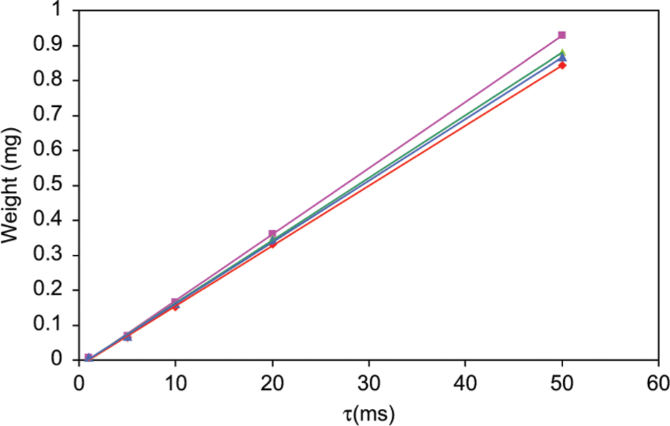
Dispensing of a single droplet is a dynamic process that depends on both the ambient pressure of the dispensed fluid as well as the length of time the valve is open. As the drop leaves the valve, it hits the target’s surface and transfers the momentum, causing dynamic perturbation of the WM output signal. This momentum force is given by
Dynamic response of the weighting module for the single droplets generated at various valve opening times: ▲ - τ = 20 ms, ● - τ = 30 ms, ♦ - τ = 50 ms.
Continuous (Multidrop) Operation Regime
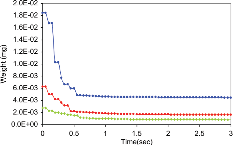
The precision of the dispensing system is tested by recording the mass of aliquots as they are collected. Figure 6 depicts time history of the polar solvent droplets (readings are collected every 250 ms). The different lines in the figure correspond to different times used to keep the valve opened. The longer the opening period for the valve, the larger the mass of liquid dispensed.
Mass of model fluid dispensed systematically into target container (vial) using different valve opening times: □ - τ = 5 ms, ♦ - τ = 10 ms, ▲ - τ = 20 ms, ● - τ = 30 ms, ■- τ = 40 ms.
Testing the System With Pharmaceutical Formulations
Finally, the microdispensing system is used to administer model drugs, with a solution of drug, solvent, and polymer that are relevant compositions for many pharmaceutical processes. We have prepared a set of pharmaceutically relevant model fluids as described in Table 1 .
Model Drug Formulations.
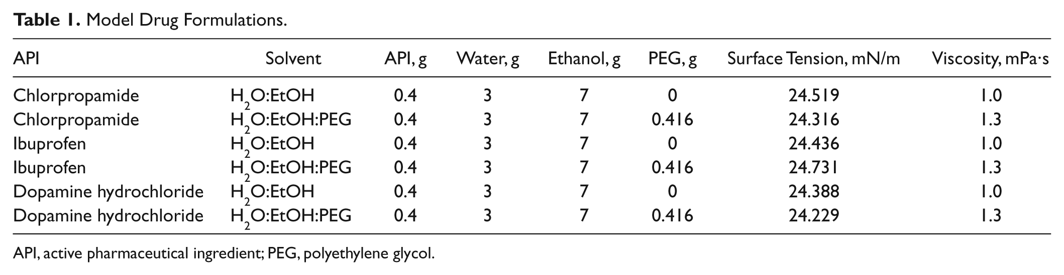
API, active pharmaceutical ingredient; PEG, polyethylene glycol.
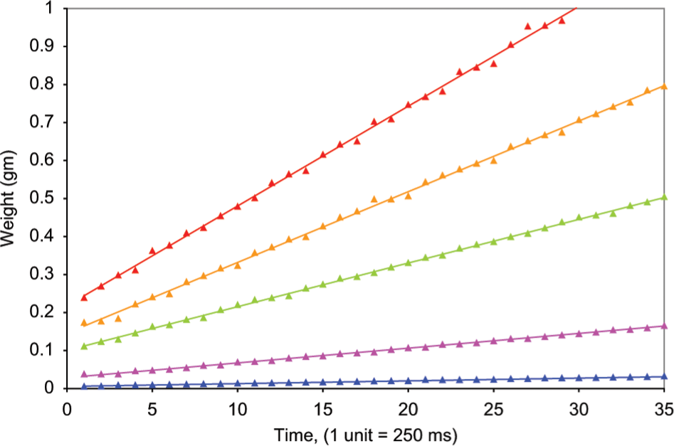
The linear correlation between the opening time for the valve and the mass of solution dispensed after 100 cycles is depicted in Figure 7 . Different amounts of the different fluids pass through the valve while it is open for a specific period of time. The mass of liquid dispensed increases from chlorpropamide/polyethylene glycol (PEG) to an H2O/ethanol one. A correlation can be seen between the viscosity and the mass of fluid dispensed. The correlation between valve-opening time and mass dispensed in 100 cycles for all fluids is near perfectly linear with R2 = 1, which is in good agreement with the theory. 12
Correlation between opening time of the valve and fluid mass dispensed after 100 cycles: ◊ - chlorpropamide (H2O:EtOH), ▲- chlorpropamide (H2O:EtOH:PEG), ○ - dopamine hydrochloride (H2O:EtOH) and ■ - dopamine hydrochloride (H2O:EtOH:PEG).
System Repeatability
The capability of the system to administer dosages with high repeatability is tested. To accomplish this aim, each experimental condition (i.e., 100 cycles with a specific time of opening for the valve) is tested 10 times. The standard deviation of the 10 dosages is estimated as well as the relative standard deviation (RSD).
Our data indicate that the standard deviation of dosage mass increases linearly with the time used in the protocol for the opening of the valve. In this experiment, dosages are made of 100 aliquots dispensed at different valve opening times. Figure 8 depicts that the RSD first decreases and, for larger opening times, (>30 ms) stays at a constant value. For the operating system and the hardware used in these experiments, RSD is generally better than 1% for the valve-opening times.
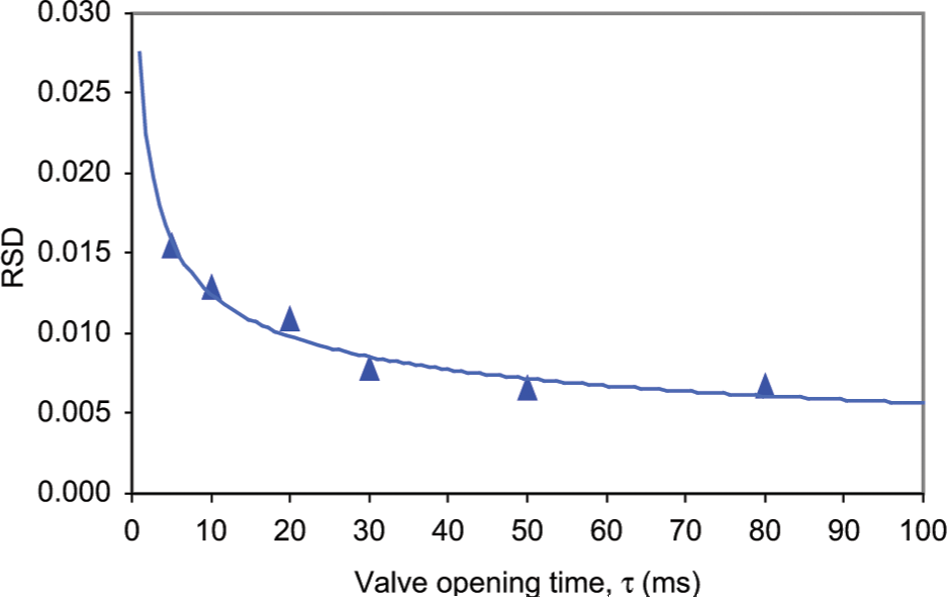
Relative standard deviation of the dosage mass for printed ibuprofen in the H2O:EtOH system.
Figure 8 can be used as a calibration curve for the dispensing system and to establish the dosage error for a protocol with a specific time of opening for the valve, respectively. To minimize the RSD of larger doses beyond 0.6% while still keeping a high throughput, it may be possible to use a protocol that combines large and small aliquots. However, the optimum combination of aliquots for a specific dosage is a matter of an additional experimental study.
Unit Dosage Application: Filling Mode
For a given opening time of the valve, every fluid portion dispensed into the receiving container should increase the total mass by a constant value, and the WM reading should increase linearly. Therefore, the aliquot reproducibility is assessed by measuring the deviation of the balance recording (total fluid mass vs the number of aliquots dispensed) from a straight line. The results show that, in general, the gravimetric readings fit a straight line with an R2 ≥ 0.995.
We have assessed an ability of the system to dispense any desired amount of model fluid with the appropriate combination of cycles and opening time of the valve (see Fig. 9 ). The opening time of the valve is a critical parameter in the design of a dosage expending protocol. For example, using the system for 100 cycles and different opening times of the valve, a correlation between the latter and the fluid mass dispensed can be established. Our data show that the mass of water dispensed after 100 cycles increases linearly with the time used for the opening of the valve. The correlation between valve opening time and the fluid mass dispensed in 100 cycles is perfectly linear with R2 = 1 (data not shown). Therefore, it is possible to design a microdispensing operation with the high level of accuracy and reproducibility.
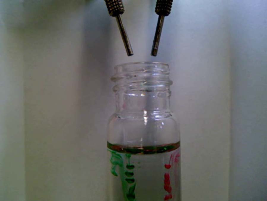
Filling vial with drug formulation via two-nozzle microdispensing setup. Pharma-grade coloring agents have been added for visualization purposes.
Unit Dosage Application: Printing Mode
Another application evaluated is the ability of the system to print precise and reproducible amounts of drug solutions onto varying substrates. This ability is necessary in the design of a drug delivery system (DDS), which entails precision dosing, time-dependent dosing, or other advanced delivery modes (e.g., matrix drug delivery in controlled DDS). In printing mode, the system parameters such as opening time of valve (τ), column and row distance, and pressure are manipulated to obtain printed drops of drug solution of desired quality. To ensure that the desired product is obtained, it is critical that all system parameters are accurate and easily controlled.
Variation of key parameters of the system enables the production of printed solutions and DDS with desired properties. In some instances, reproducibility and accuracy are desired, whereas in other applications, droplets with varying properties are produced. Figure 10 depicts drug printing with variations in impingement substrate and/or process parameters.
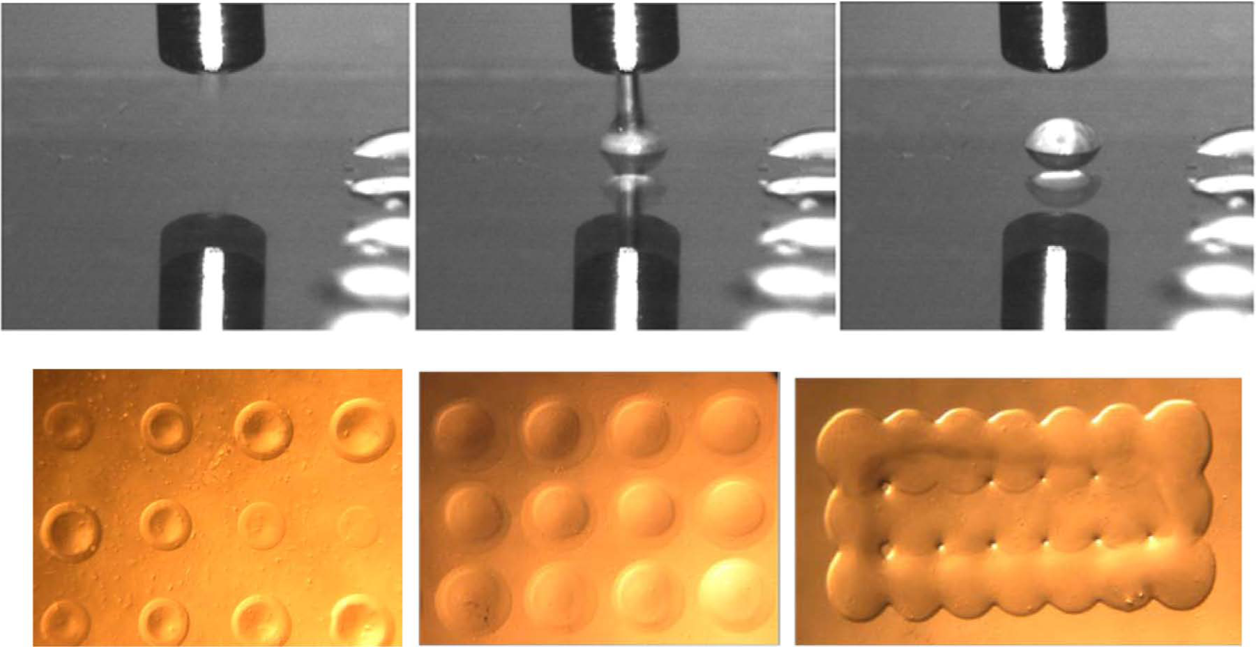
High-speed imaging of the dopamine hydrochloride printing and resulting surfaced patterns produced through manipulation of key process parameters: ramp of variable valve opening times τ, regular square lattice array pattern, and printed array with overlapped active pharmaceutical ingredient elements.
To test the accuracy and robustness of the system, two experiments were undertaken. In the first experiment, a single drop of dopamine hydrochloride solution was deposited onto a biopolymeric substrate at increasing τ, resulting in increased droplet volume. The droplet diameter at each τ was then measured for six trials to determine the robustness and repeatability of the DoD system in printing mode. In the second experiment, 25 droplets of approximately 4 × 10⁻⁴ mL were deposited simultaneously to measure the droplet weight. The average weight and the standard deviation can be seen in Table 2 .
Droplet Diameter and Droplet Weight.
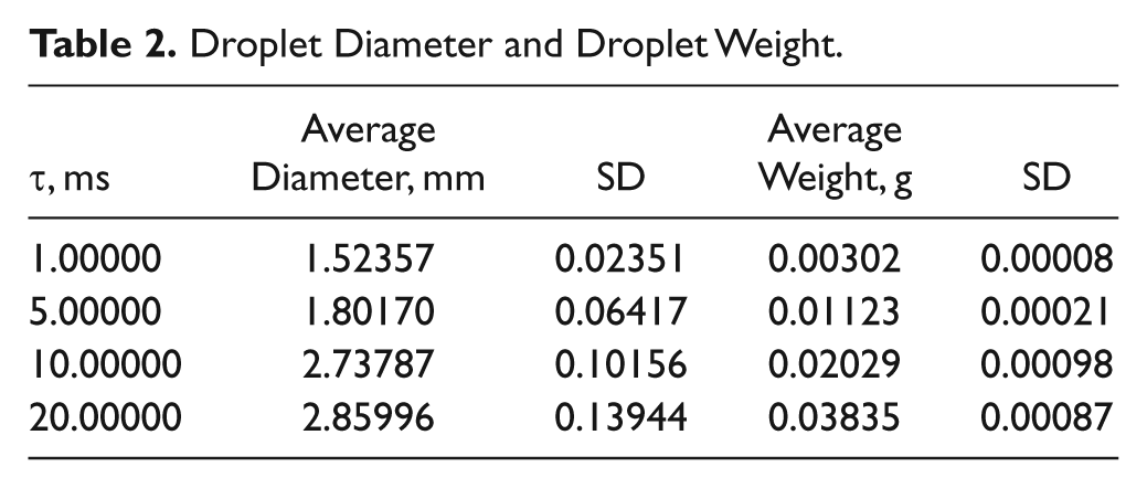
We have found that in printing mode, the system is robust, precise, and accurate. It enables for the production of advanced drug delivery systems through automation. Varying types of drops using different drug solutions are able to be printed within exact range. Furthermore, the system provides increased efficiency and allows for easy adaptation in the printing of different types of drug patterns, droplet diameters, and drug type.
Conclusion
Droplet generation is an essential step in DoD system operation, as a droplet is the basic unit of filling/printing operations. A reliable operation is important because the volume of each droplet is determined in the generation step. An all-automated method to generate droplets train for filling or printing a pharmaceutically relevant solution allows a self-sufficient portable mini-manufacturing platform for customizable dosage formulation. We have successfully designed and implemented hardware and software for the real-time feedback control, in combination with the drop-on-demand generation with solenoid actuation and real-time gravimetric control. The all-electrical feedback control system has potential for practical applications. We show the possibility of the generation of varying volumes of droplets on a given pattern in printing mode. Proposed feedback control system parameters and an algorithm can be easily programmed with a PC. The former can improve device reliability by compensating for the uncertainties in the dispensing nozzle, dispensing fluid properties, and operation conditions, whereas the latter allows a new flexibility in fluidic operations, such as a high-order solution dilution. More sophisticated and advanced feedback control algorithms, supported by detailed modeling of the nonlinear droplet pinch-off process where still a lot of research needs to be done, are expected to improve convergence speed, stability, system error, and robustness of the control system. Through automatic system identification or neural network studies, the feedback controller may be improved in the future to self-calibrate for different solutions and devices without human intervention.
Footnotes
Declaration of Conflicting Interests
The authors declared no potential conflicts of interest with respect to the research, authorship, and/or publication of this article.
Funding
The authors disclosed receipt of the following financial support for the research, authorship, and/or publication of this article: This work was financially supported by the USDA NRI grant and NSF ERC for Structured Organic Particulates.