
Abstract
A rod-and-pedicle screw construct is a common and effective surgical technique in posterior spinal instrumentation. Percutaneous pedicle screw (PPS) systems can be used in various conditions such as degenerative conditions, trauma, and malignancy. Compared to traditional open surgery, minimally invasive spine surgery (MISS) is proposed to have the advantages of less intraoperative blood loss, lower iatrogenic injury, wound complication rate, and a quicker return to daily activities. However, the contouring of rods has long been a technical challenge, especially for long constructs. Several technologies have been described to overcome this surgical difficulty, including utilizing a computer assisted method and augmented reality method for rod bending. In this article, we describe a novel technique to obtain patient-specific, prebend rods preoperatively by applying three-dimensional (3D) printing technology in a case of PPS fixation in MISS. This could save operation time and provide an alternative method for rod bending, in particular when other methods are not available. To our best knowledge, the implementation of 3D printing technology for rod-bending in minimally invasive spine surgery has never been reported before.
Introduction
The application of percutaneous pedicle screw (PPS) system in minimally invasive spine surgery (MISS) can be dated back to 2005. Since then, it has been gaining popularity across the world. Over 40% of spinal fixation surgery in Japan (by 2017, from Yano Research Institute Ltd, Tokyo, Japan) and the United States (by 2014, from North American Spine Society) were performed using PPS system. 1 MISS is proposed to have the advantages of less intraoperative blood loss, infection rate, postoperative pain, and a quicker return to daily activities. 2
Despite the potential benefits of MISS, Sclafani et al. 3 suggests that there was a certain learning curve that spine surgeons must overcome, before which there may be increased complication rates. For multilevel PPS fixation construct, rod contouring presents an important challenge.4,5 As such, we proposed a method to utilize the three-dimensional (3D) printing technology for rod contouring and preoperative preparation.
Case report illustration
A 48-year-old woman with newly diagnosed carcinoma of right breast has multiple bone metastases including the L1–L3 vertebrae. X-ray and plain computed tomography of the lumbosacral spine showed pathological L2 vertebral collapse of around 50% with erosion of one-third of the body and bilateral posterior elements (Figures 1 and 2). There were also lytic lesions over L1 and L3 pedicles, sparing the vertebral bodies. There was no cauda equina compression in the magnetic resonance imaging (MRI) study. The Spinal Instability Neoplastic Score (SINS) System score is 15.
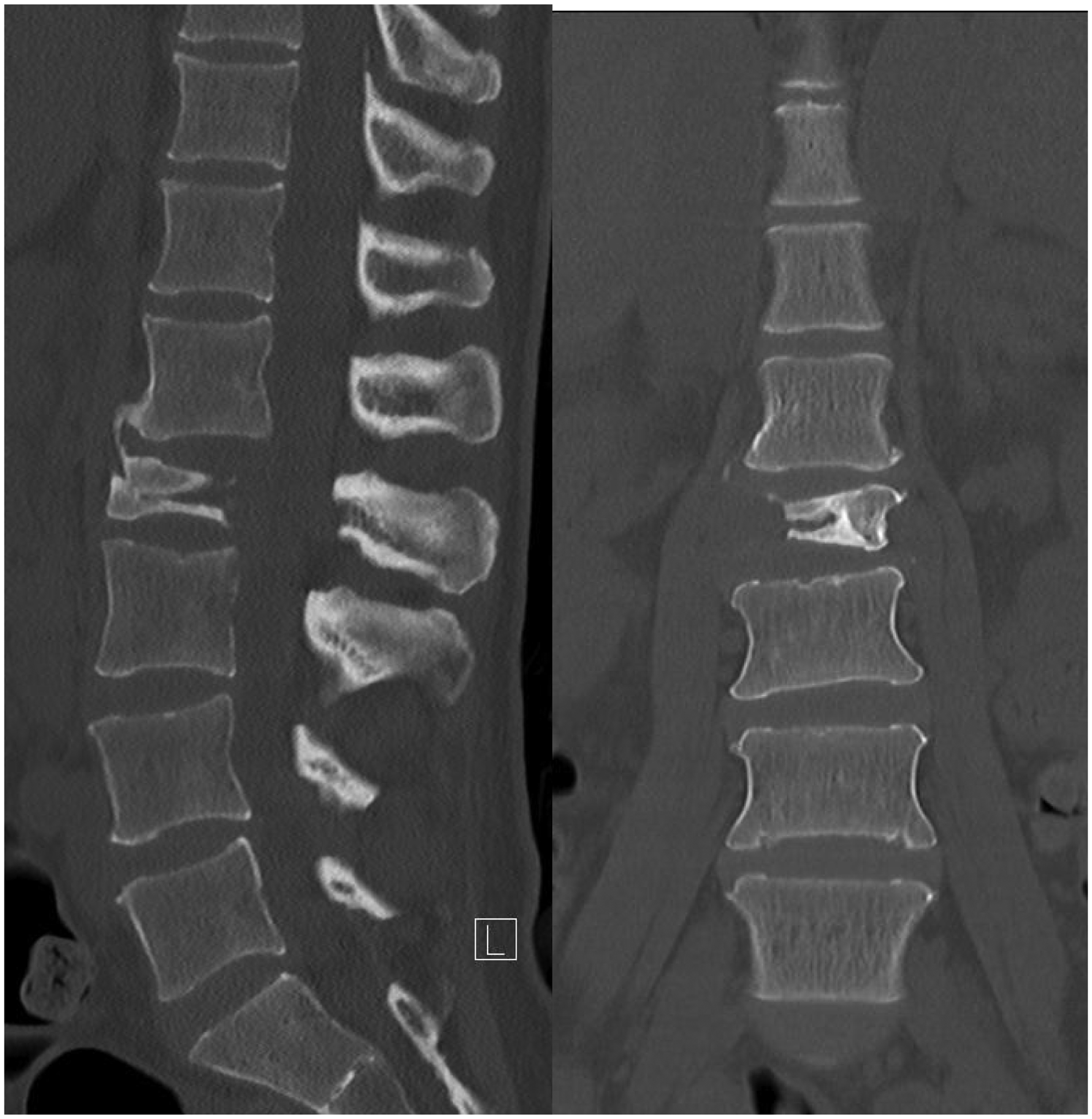
Plain computed tomography of the lumbosacral spine showing L2 pathological erosion (left: sagittal view; right: coronal view).
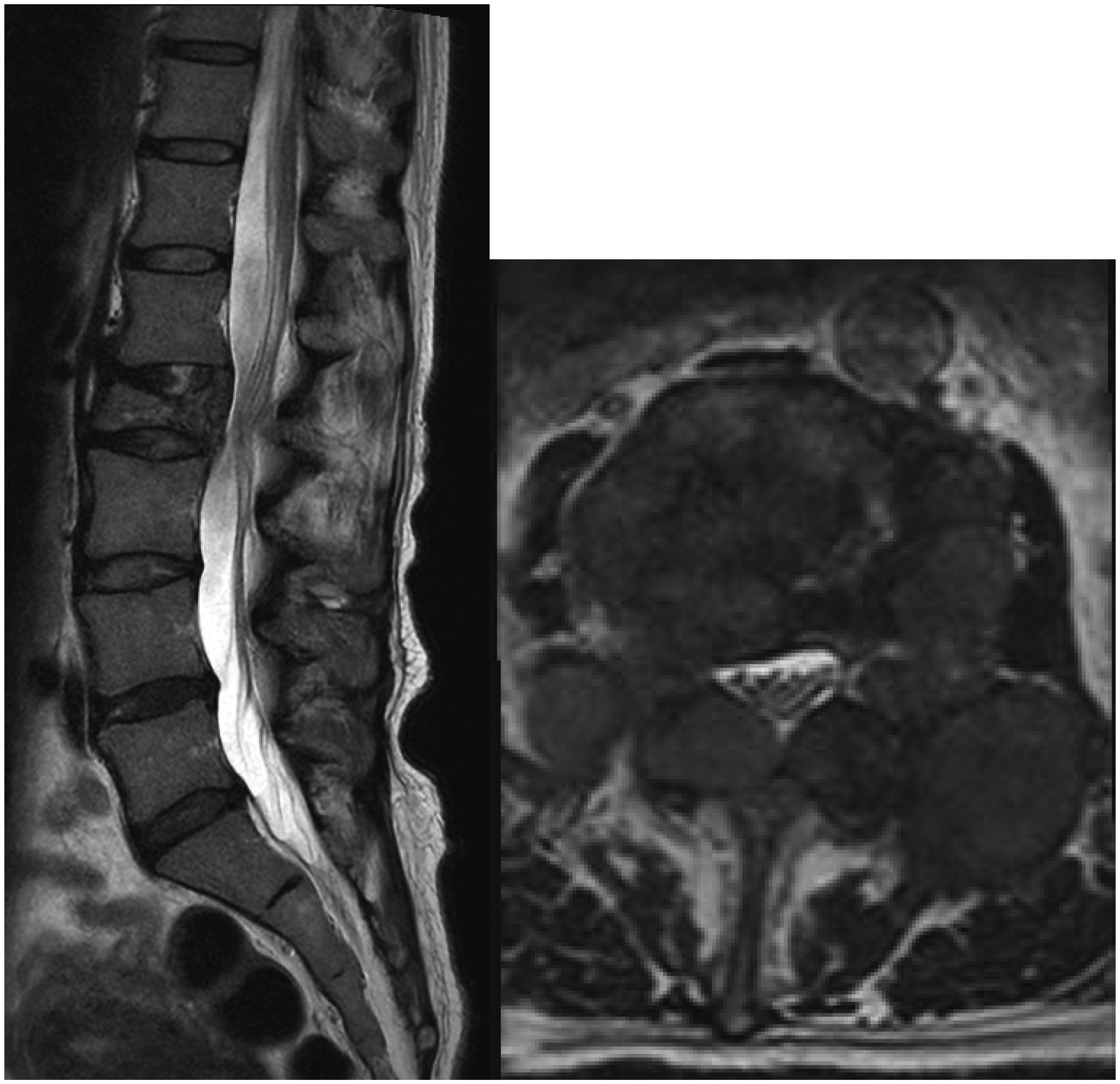
T2-weighted magnetic resonance image showing tumor invasion of L2 with no cauda equina compression (left: sagittal view; right: axial view across L2).
For surgical planning, in view of metastatic disease, palliative surgical stabilization was performed for spinal instability and mechanical back pain. Minimal invasive spinal surgery with PPS fixation for L2 pathological fracture was planned to reduce surgical morbidity, facilitate wound healing and hence early oncological treatment such as radiotherapy and chemotherapy. Reduction and decompression were not performed due to acceptable alignment and absence of neural compression. Vertebroplasty was not performed due to erosion of the posterior wall. As there were partial lytic lesions over L1 and L3 pedicles, posterior PPS system stabilization on three superior and three inferior vertebral levels from the lesion, spanning from T11 to L5, was planned. A long construct PPS fixation appeared particularly beneficial to this patient with comorbidities and limited life expectancy, as it provided greater primary stability for potential unstable lesions and averted the future need of revision procedure. This also allows the patient to mobilize early and return to usual life.
Technical Notes on 3D printing
A 1:1 ratio 3D-printed spine model from T11-L5 vertebrae and pedicle screw head tulips were needed for preoperative preparation. For the spine model, patient specific spine plain CT image (Figure 3) was acquired for segmentation. Targeted spinal vertebrae (T11-L5) were segmented using semi-automated Hounsfield intensity threshold value. Segmented data was refined and constructed into a visualized solid 3D virtual spine model (Figures 4 and 5). For the screw head tulips, pedicle screw of the spinal system was scanned by a 3D scanner. Virtual model of screw head tulip was then isolated and segmented from digital image of pedicle screw. The respective 3D virtual models with semi-automated support structure generation were printed by a fused deposition modeling (FDM) 3D printer, which took around 15 to 20 hours.An additional 30 to 60 minutes was required for model segmentation and verification. Measurement and dimensions of 3D-printed spine and screw heads models were verified by digital caliper.
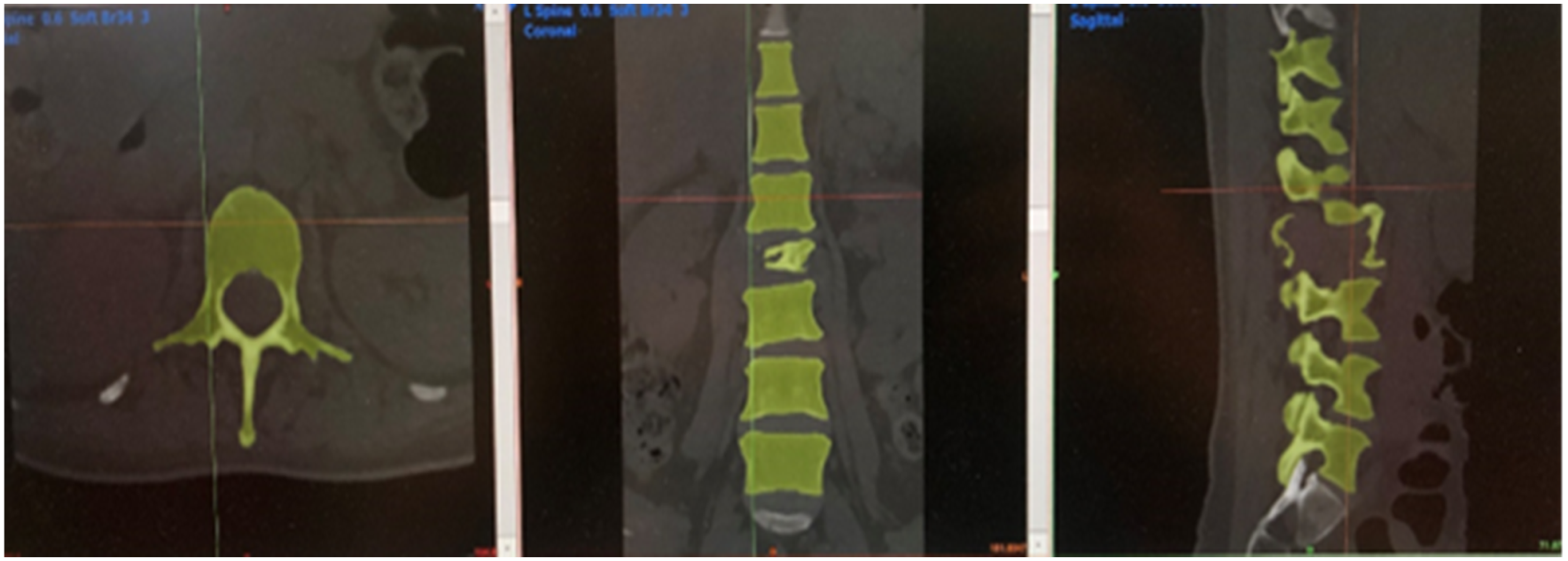
DICOM file with patient-specific plain computed tomography spine image (left: axial; middle: anteroposterior; right: lateral).
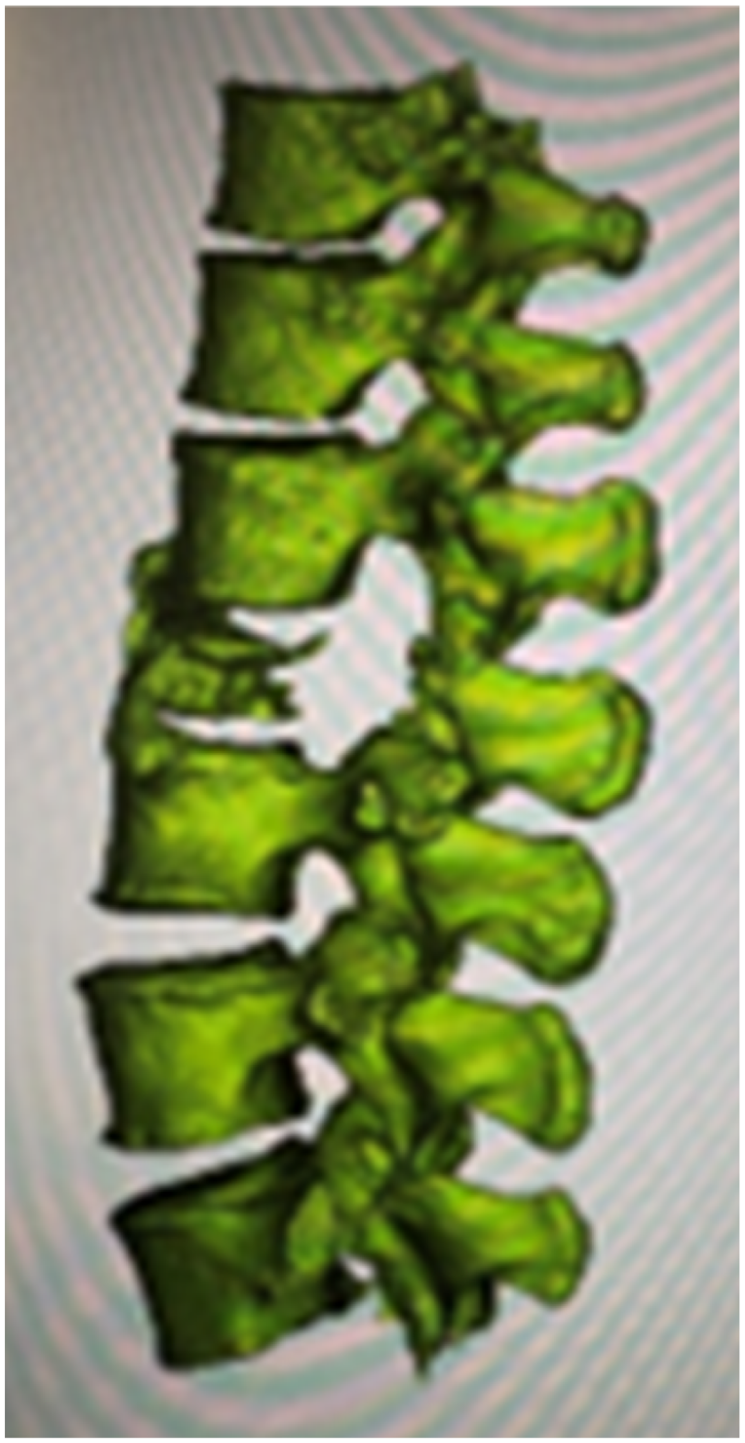
(Left) Visualized solid three-dimensional virtual spine model.
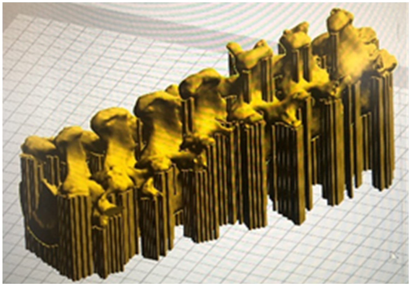
(Right) Visualized solid three-dimensional virtual spine model with support structure generation in printing bed.
The 3D-printed spine model and pedicle screw head tulips were assembled and secured with putty-like adhesive (Blu-Tack, Bostik), at the entry site of pedicles as if the pedicle screw were inserted. The thickness of the adhesives was made as thin as possible to keep the tulip in place. The degree of freedom of tulips was determined by examining the selected pedicle screws, mimicking the 15 degree poly-axial character of screw heads. The connecting titanium rods were cut and bent, labeled with serial number printed on the implants. This process took about 70 minutes. Subsequently the rods were autoclaved for intraoperative use (Figures 6 and 7).
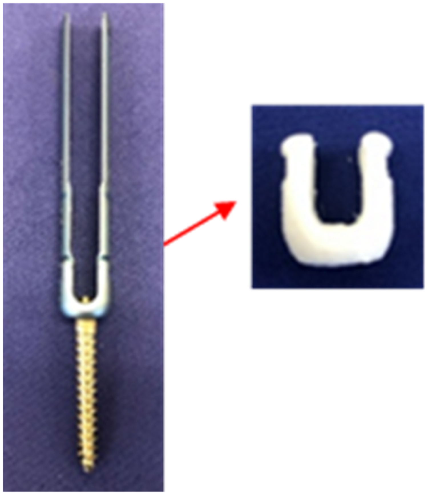
Three-dimensional printed pedicle screw head tulips.
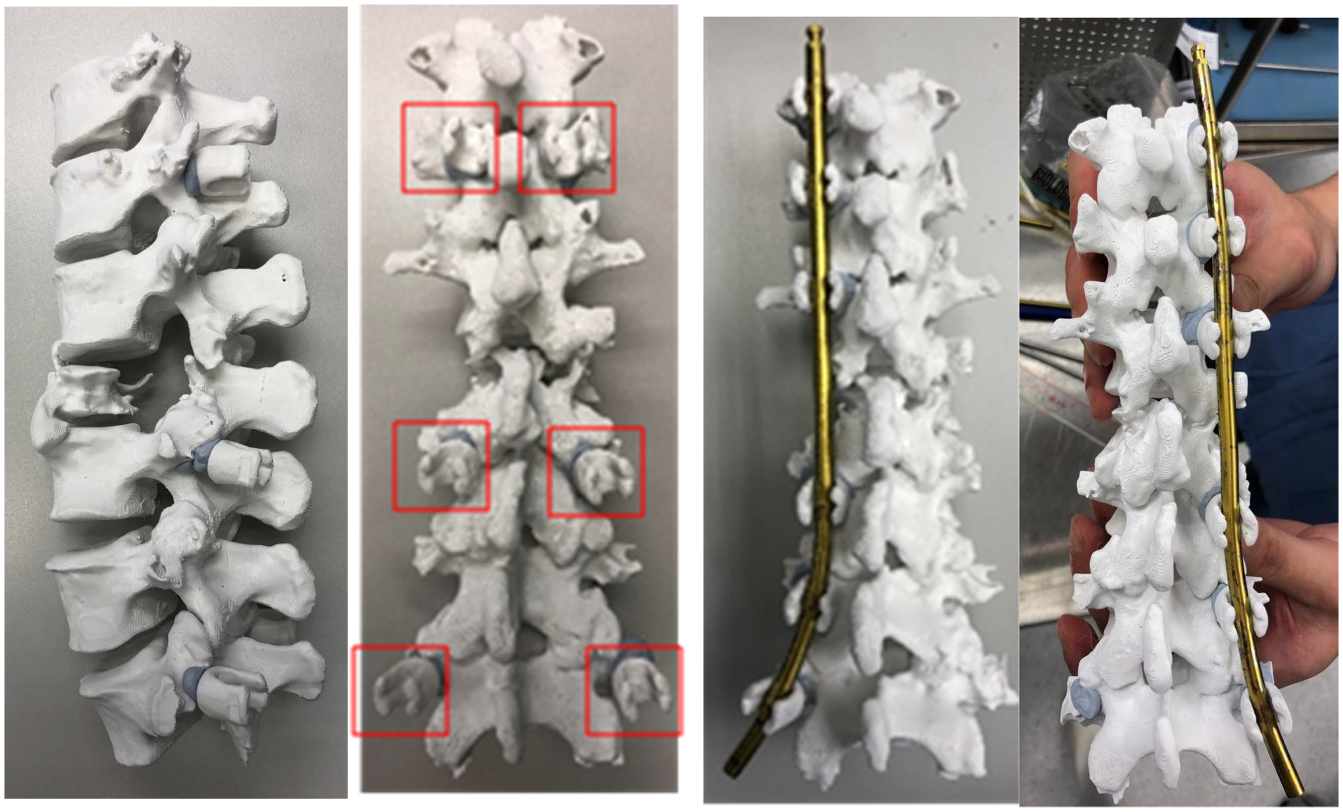
Three-dimensional printed spine model from T10-L5 (left: lateral view; middle: posterior view with some screw head tulips anchored; right: prebend rod anchored).
Operation was carried out with the Stryker Nav3i navigation and Stryker ES2 pedicle screws system. Navigation tracker was anchored to the L4 spinous process, for pedicles screws insertion over L3 to L5 percutaneously under 3D fluoronavigation guidance. The procedure was repeated for T11 to L1 pedicle screws with navigation tracker attached to T12 spinous process. Subsequently, the prepared titanium rods, 5.5 mm in size, were inserted percutaneously. The passage of the rods was smooth and in a single pass. Further adjustment for rod contour and length was not required. Fluoroscopy confirmed well-contoured rods fitted into all pedicle screw tulips.
After the operation, the patient could walk with a frame the next day with satisfactory pain level. On subsequent follow up of 6 weeks later, the patient could walk unaided with no back pain or lower limb neurology. All wounds were healed. Radiotherapy to vertebrae and pelvis metastases had commenced. XR showed that sagittal alignment was maintained with no pull-out of screws (Figures 8 and 9).
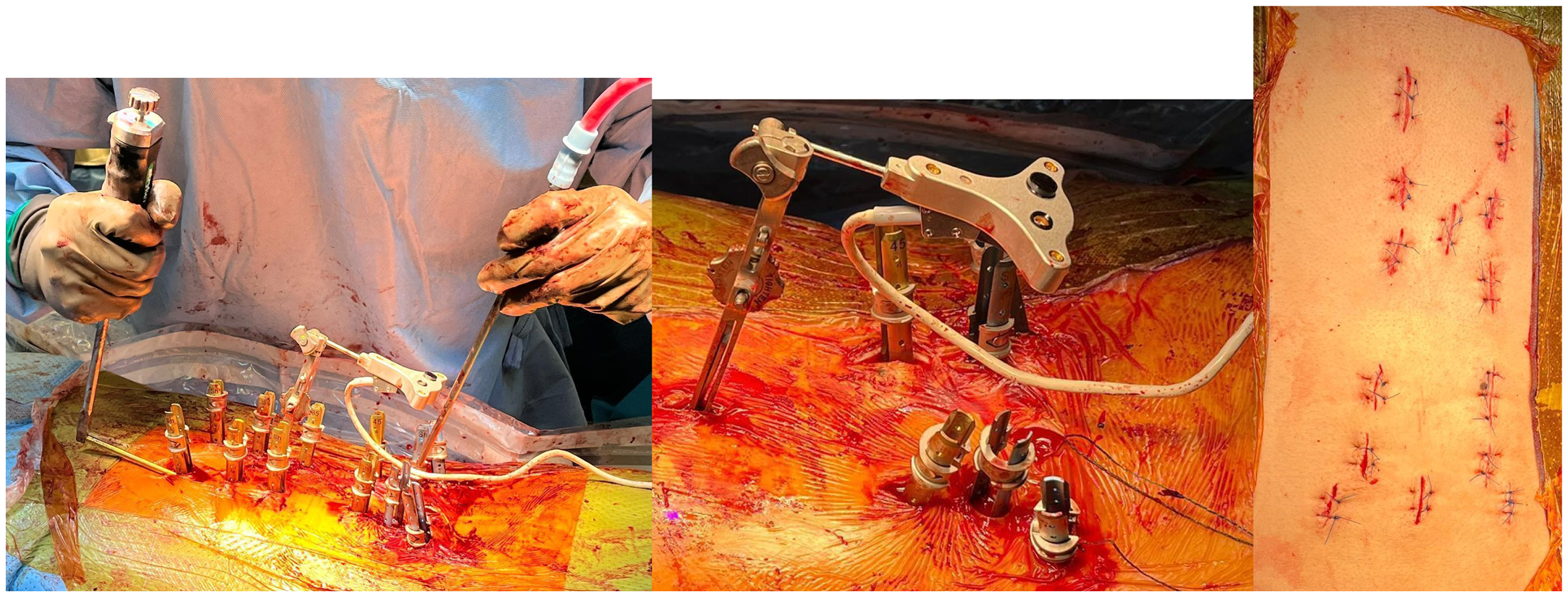
Intraoperative photos (left: rod insertion; middle: showing navigation tracker and extended tab of pedicle screws; right: wound after closure).
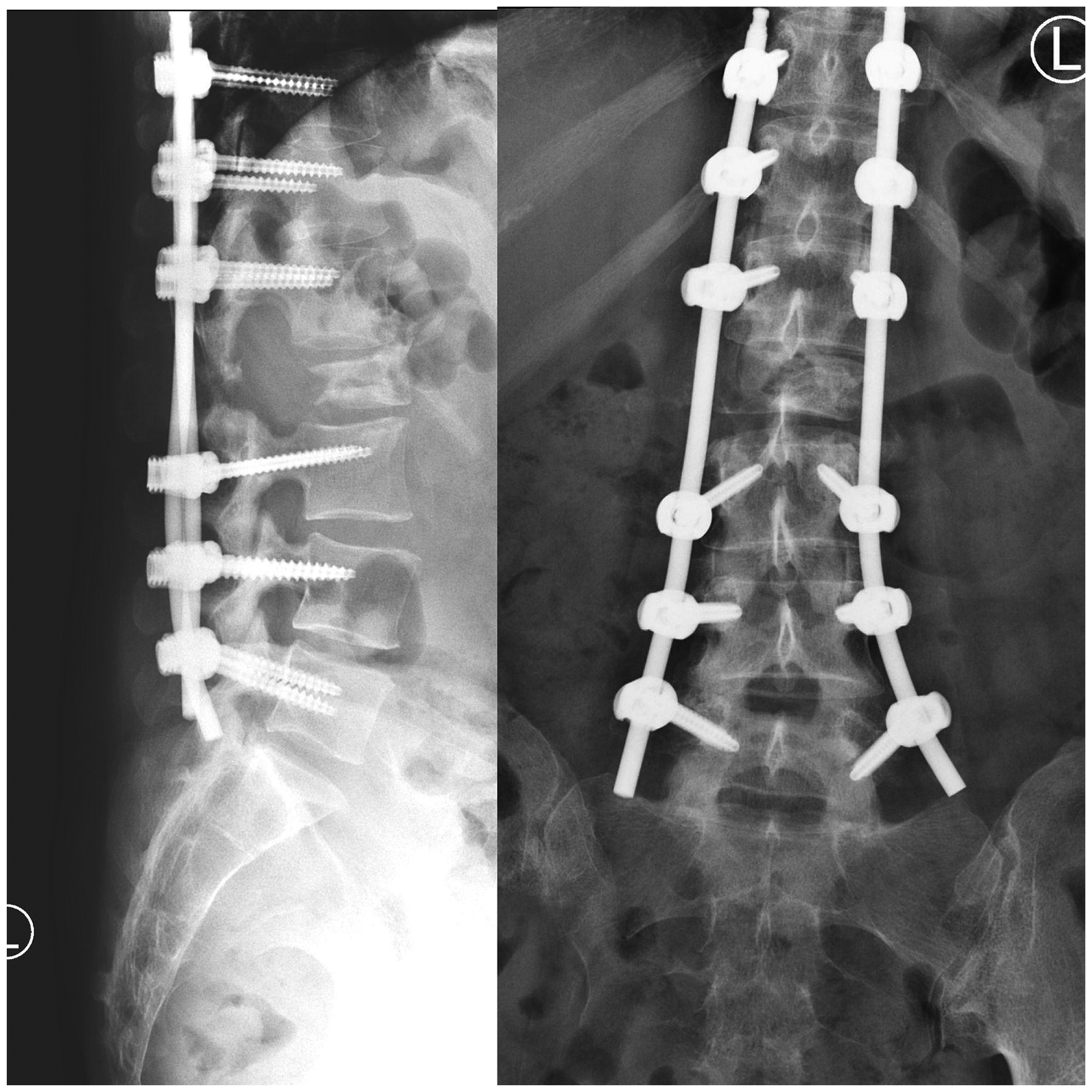
Postoperation X rays.
Discussion
Following the development and popularity in PPS fixation surgery, there are a number of systems flourishing in the market with emerging advancement, from the first generation SEXTANT® PPS system (Medtronic), which is mainly used for 1 to 2 vertebral level fusion; to the second generation which features stronger extender assembly to screw head to enable powerful reduction, and are able to link to navigation systems; to the third generation with addition of an extended tab to facilitate slippage correction. Recently, the fourth generation, which eliminated the need for conventional guidewires, was introduced from 2019 onwards. With the advancement of PPS systems, aided rod introduction is made possible. Many systems feature extenders with slots that lines up with each screw head, allowing hand control of screw head rotation for passage of rods and subsequently secured with set screw caps. There are pedicle screw heads designed with 15 degree polyaxial feature, to permit some degree of flexibility in screw heads alignment for rod passage. Despite the emergence of the aforementioned design, it is still essential to achieve accurate rod contouring for rods to be successfully anchored within screw heads and without exerting an undesirable pull-out load. A mal-contoured rod may exert an undesirable biomechanical load, increasing the risk of screw pull-out and inducing soft tissue deformations. 6 Therefore, the significance in precise rod contouring should not be underestimated.
Precurved lordotic rods are commercially available for short segment lumbar region fixation. While for thoracic or thoracolumbar fixation, freehand contouring is often required. Furthermore, the difficulty of rod bending and percutaneous rod insertion increases with more levels of vertebrae involved,4,5 due to the specific contour of spinal curvature and pre-existing deformity. While there have been continuous advancements to overcome various challenges in PPS system, the realm of percutaneous rod contouring remains under-explored.
In traditional open surgery, rods contouring could be performed under open visualization of anatomy, direct manipulation of the screw heads and fine adjustment with an in situ rod bender. However in the PPS system, the working and visualization fields are limited. Rod contouring relies on the surgeon's knowledge on anatomy and experience, the tactile feedback between rods and screw heads, as well as fluoroscopy estimation of spinal curve comparing with the rod curve. This indirect bending could lead to multiple trial-and-errors on inserting and removing rods through subcutaneous and subfascial path for contour adjustment, leading to undesirable iatrogenic muscle injury and false tracts. Fluoroscopy-guided adjustment exposes the surgical team and the patient to increased radiation dose. Furthermore, study has demonstrated rod contouring will reduce rod yield strength and stiffness in all kinds of materials. 7 Thus, the repeated trials of rod bending may create undesirable detriment on mechanical properties of rods. Surgical time and hence intraoperative bleeding may also be increased.
Considering the complexity and individuality, several methods to achieve rod contouring in PPS fixation were developed. Ohba et al. 8 suggested a computer assisted system, utilizing digitizer to locate the screw heads and capture their positions by an infrared motion tracking camera. Rod bending is then performed with instructions including distance, rotation, and bend angle. Atzigen et al. 9 suggested an Augmented Reality-based navigation to achieve rod bending in PPS. A stereo neural network is trained from the stereo video streams of the Microsoft HoloLens to digitize screw head positions and calculate optimal rod shape to guide the surgeon step-by-step. These two focus on advanced navigation systems for intraoperative rod-contouring.
Ishikawa et al. 10 developed a preoperative prebend rod system for adolescent idiopathic scoliosis (AIS) open corrective surgery. It traced rod contour information in previously operated patients with AIS and used a computer-aided design operator, to manufacture a more anatomical prebend rod before operation. This technique generates a more suitable rod model for patients with AIS due to theoretically less intra-operative rod bending and fine tuning. It demonstrated the merits and emphasized the essence of generating a prebend rod for distinct or difficult cases.
In this literature, we introduce a de novo method utilizing 3D-printing technology as an alternative for rod bending, to manufacture a personalized, patient-specific rod model for PPS fixation. Concerning the 3D-printing technology for spine surgery, the common applications lie in generating 3D models for education purposes, pre-operative planning such as molding of patient-specific jigs or guides to optimize instrumentation placement; manufacturing individualized implants and for off-the-shelf modification of implants. Our method demonstrated an innovative direction of application, which is to preprint a patient's anatomical model to use as a guide for molding implants in the preoperative period.
This method is proposed to have several advantages. Firstly, it was done in the preoperative period, sparing operation time and associated morbidity in prolonged surgery. Secondly, it generates individualized implants according to the patient's unique anatomy and deformity. The technique produces a rod with contour that can fit in the screw head percutaneously, followed by minor adjustment with polyaxial screw heads and rod flexibility. This ensures minimal internal stress within the construct. Thirdly, it overcomes the bottleneck with current PPS systems, which is a lack of pre-bent thoracic curve rods by most manufacturers; only lordotic curve rods are generally available. This method enables selected patients who require a long construct extending to thoracic levels to be done in MIS. Moreover, it can serve an educational purpose for junior spine surgeons who are in the beginning of their learning curve, eliminating the stress in real operation.
Nonetheless, the technique described in this article has its limitations. This approach requires the use of navigation technology in order to be accurate and effective. The accuracy of the pre-bent rod can be affected by multiple factors. The technique mentioned should be reserved for patients who require minimal correction of deformity. If an operation involves deformity correction prior to stabilization procedure, preoperative printed 3D model of the patient's spine would not match with the curvature after operative correction. Furthermore, the pathway for rod insertion is determined by pedicle screws’ entry site and trajectory in the actual operation. Thirdly, the printed tulips could not fully mimic the degree of freedom of the real tulips, despite being only adhered with adhesives.
To overcome these shortcomings, a desired model of deformity correction with proper pedicle screws position could be simulated during the preoperative planning. This stimulated model could be 3D printed with contemplated pedicle screw entry sites marked, and anchored by screw tulip model with an additional hole at the bottom, for secure attachment onto the 3D spine model. The hole in the bottom of the 3D screw tulip model can mimic screw head polyaxial property. Subsequently, a pre-bent rod could be generated with reference to patients’ anatomy, planned deformity correction and pedicle screw insertion sites.
As the popularity of MISS flourishes, continuous advancement and progress is needed to support its stride. This de novo method for preoperative preparation of rod in PPS system with 3D-printing technology may improve accuracy, efficiency, and safety of instrumentation in PPS fixation surgery.
Footnotes
Declaration of conflicting interests
The authors declared no potential conflicts of interest with respect to the research, authorship, and/or publication of this article.
Funding
The authors received no financial support for the research, authorship, and/or publication of this article.