
Abstract
Study Design
Basic science (finite element analysis).
Objectives
Pedicle subtraction osteotomy (PSO) at L5 is an effective treatment for sagittal imbalance, especially in select cases of patients showing kyphosis with the apex at L4-L5 but has been scarcely investigated. The aim of this study was to simulate various “high-demand” instrumentation approaches, including varying numbers of rods and sacropelvic implants, for the stabilization of a PSO at L5.
Methods
A finite element model of T10-pelvis was modified to simulate posterior fixation with pedicle screws and rods from T10 to S1, alone or in combination with an L5 PSO. Five additional configurations were then created by employing rods and novel porous fusion/fixation implants across the sacroiliac joints, in varying numbers. All models were loaded using pure moments of 7.5 Nm in flexion-extension, lateral bending, and axial rotation.
Results
The osteotomy resulted in a general increase in motion and stresses in posterior rods and S1 pedicle screws. When the number of rods was varied, three- and four-rod configurations were effective in limiting the maximal rod stresses; values approached those of posterior fixation with no osteotomy. Maximum stresses in the accessory rods were similar to or less than those observed in the primary rods. Multiple sacropelvic implants were effective in reducing range of motion, particularly of the SIJ.
Conclusions
Multi-rod constructs and sacropelvic fixation generally reduced maximal implant stresses and motion in comparison with standard posterior fixation, suggesting a reduced risk of rod breakage and increased joint stability, respectively, when a high-demand construct is utilized for the correction of sagittal imbalance.
Introduction
Adult spine deformities frequently involve a forward tilt of the trunk that is commonly assessed radiologically by measuring the sagittal vertical axis, ie, the distance between the C7 plumbline and the posterior superior corner of the S1 endplate. 1 This posture, commonly named “sagittal imbalance”, is a complex phenomenon that involves degenerative changes in bone and discs that may determine a loss of the lumbar lordosis potentially in combination with increased thoracic kyphosis, as well as compensatory mechanisms aimed at restoring a global alignment compatible with gait and daily activities. 2 It has been demonstrated that sagittal spine deformities are associated with pain, disability, and loss of quality of life, especially in severe cases.3,4
An approach for the surgical treatment of sagittal imbalance aims at creating a locally high lordosis in the lumbar spine by means of a wedge-shaped osteotomy known as a pedicle subtraction osteotomy (PSO). 5 This technique, most commonly performed at L3 or L4, 6 has gained prominence since it allows for a high degree of local correction up to 30°, 5 and clinical studies have shown that the restoration of a physiological lordosis results in a spontaneous correction of the compensatory mechanisms and significantly improves the quality of life. 7 Per Berjano and Aebi, posterior fixation spans from two levels above to two levels below the PSO and often involves the pelvis when fixation must extend into the sacrum. 6 While a PSO has been an effective means of correcting sagittal imbalance, the technique inherently creates instability requiring its own correction with additional hardware. 8 Complications include pseudarthrosis and rod breakage.9-14
Though less common, PSO at L5 has also been performed to treat sagittal imbalance (Figure 1). Although clinical outcomes evidence is scarce, one clinical case series concluded that PSOs in L5 are an effective means of treating sagittal imbalance
15
while a recent paper advocated the use of PSO in L5 in select cases of patients showing kyphosis with the apex at L4-L5.
16
Perhaps more so than PSOs performed at higher regions of the lumbar spine, PSOs at L5 pose additional challenges given the higher loads experienced at the lumbosacral junction
17
and fewer caudal levels in which to place posterior fixation. Specifically, while L5 and S1 are available for posterior fixation if the osteotomy is performed at L4,
6
only the sacrum (and possibly the pelvis) can be exploited to provide stability to a PSO in L5. Clinical implementation of a pedicle subtraction osteotomy at L5 (left – lateral view; right – AP view).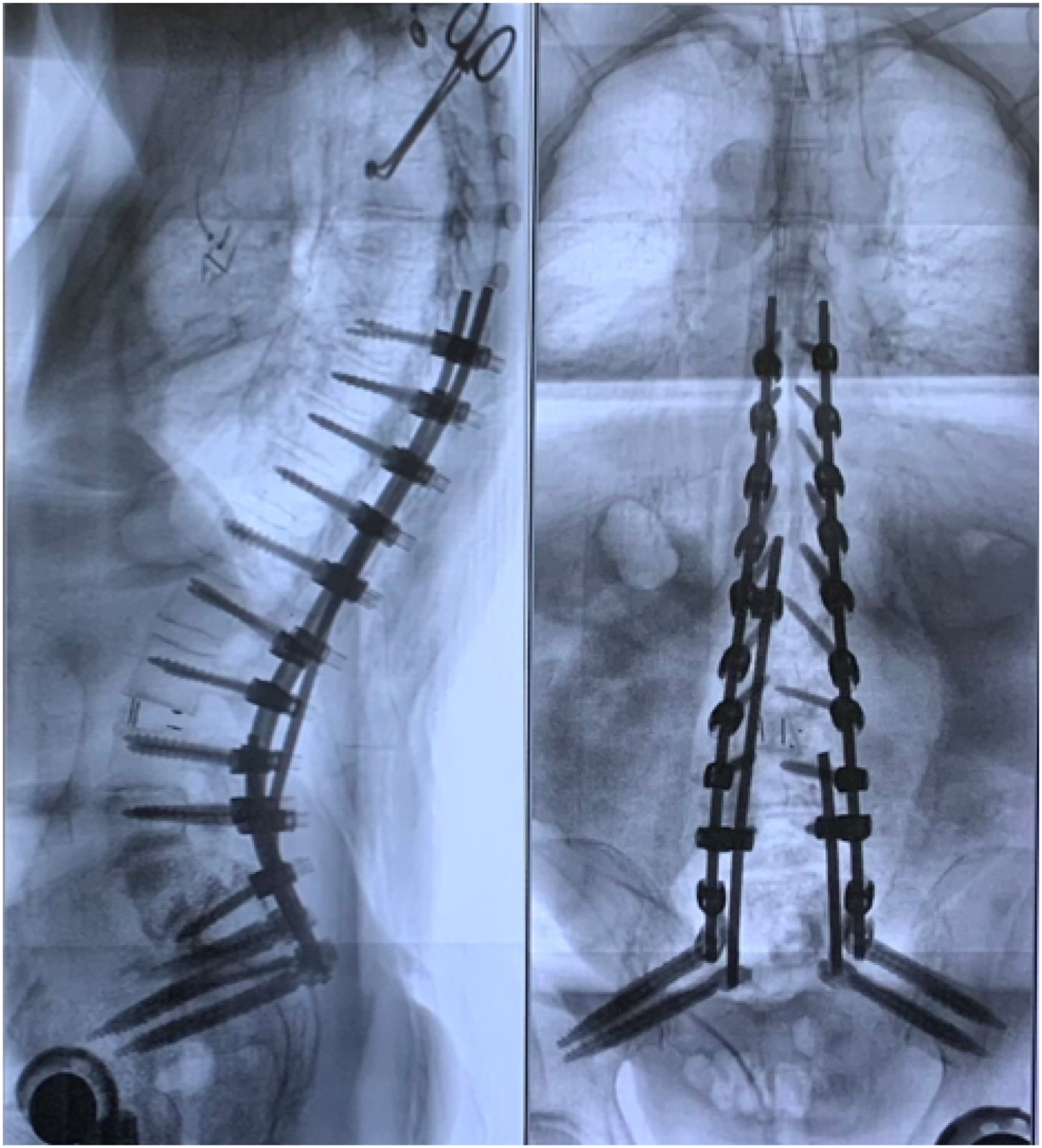
Since non-negligible instrumentation failure rates have already been reported for PSO in L4 and L36,18 and taking into account the challenging biomechanical scenario presented by an L5 PSO, fixation in order to provide additional stability deserves to be investigated.
Using finite element modelling, this study investigated various instrumentation approaches, including varying numbers of rods and sacropelvic implants, for the stabilization of a PSO at L5, what this work deems as a “high-demand” construct. Evaluated metrics included the ranges of motion across the PSO (L4S1) and at the sacroiliac joint (SIJ) and maximal instrumentation stresses, which were considered a representation of stability and the risk of mechanical failure of hardware, respectively.
Materials and Methods
Baseline Models
A finite element model of T10-pelvis developed and validated in a previous study was employed as a starting point to develop several instrumented configurations.19,20 In brief, the model was built based on computed tomography (CT) scans and included vertebrae, all major spinal and sacropelvic ligaments, and intervertebral discs. All solid structures were modelled by means of linear tetrahedral elements, while ligaments were represented by tension-only nonlinear springs with calibrated properties. 21 Facet and sacroiliac joints were modelled using gap elements. From this intact model, two instrumented models were developed and are described below; these represented the baselines against which to compare.
Posterior fixation was implemented in the model by adding pedicle screws and rods from T10 to S1 (model PED, first baseline). Pedicle screws had a length of 40 mm and a diameter of 6.5 mm; rods had a diameter of 5.5 mm. The material properties of titanium alloy (elastic modulus of 110 GPa, Poisson ratio of .3) were assigned to the implants, which were meshed with linear tetrahedral elements. Kinematic couplings were used to ensure no relative motion between the tulips and rods. The interaction between screws and bone in the T10-L5 region was modelled employing embedded elements, which join the degrees of freedom of the screw nodes that lie within the bone with the closest node in the biological tissue. Regarding pedicle screws in the sacrum, the interaction was implemented with “partially embedded elements,” which uses spring elements that connect the external nodes of the implant surfaces with the closest nodes in the bone tissue. This method, introduced in a previous study, 20 allows for the representation of physiological micromotion that was calibrated based on experimental observations.
The model was then modified to reproduce a PSO at L5 with an angle of approximately 30° (model PED-PSO, second baseline). The osteotomy was simulated following the methods described by Ottardi and colleagues 22 in which a standard contact allowing sliding and separation was modelled between the two sides of the cut. The pedicle screws in L5 were removed according to the surgical technique, and the posterior rods were reshaped by increasing the lordotic angle in L4-S1 in order to fit the adjusted positions of the tulips.
Sacropelvic Fixation and Multi-Rod Models
The effect of sacropelvic fixation was simulated starting from the PED-PSO model by adding a novel porous fusion/fixation implant (PFFI) across the SIJ (iFuse Bedrock Granite, SI-BONE Inc., Santa Clara, CA), which had a diameter of 10.5 mm and a length of 85 mm and a tulip to allow for connection with standard rods. The PFFIs were positioned in five different configurations, in different numbers and orientations with or without employing multi-rod constructs (Figure 2). In model 2PFFI-2ROD, PFFI were implanted bilaterally in a S2 alar-iliac trajectory, and each was connected to a posterior rod. Model 4PFFI-2ROD was similar to 2PFFI-2ROD but also included a second PFFI in an alar-iliac trajectory cephalad to each of the existing PFFI such that two PFFI were connected to each posterior rod. Like the 4PFFI-2Rod model, model 4PFFI-4Rod included two PFFI through each SIJ but also implemented a four-rod construct, with accessory rods connected to the primary rods at the L4 level by means of dominos. On each side, the medial rod was connected to the caudal PFFI while the lateral, primary rod was connected to the cephalad PFFI. In the 3PFFI-3ROD model, the left side was fixed with a single PFFI in a S2 alar-iliac trajectory, whereas an accessory rod and a second PFFI were implanted on the right side in the same way as in the 4PFFI-4ROD model. Finally, the 4PFFI-3ROD included two PFFI with the same orientation on the left side, such as in 2PFFI-2ROD, whereas the accessory rod was simulated on the right side in the same manner as 4PFFI-4ROD and 3PFFI-3ROD. The interactions between PFFI and bone tissue were modelled by means of “partially embedded elements” as was done for the S1 pedicle screws. The five models implementing sacropelvic fixation and multi-rod constructs: (A) 2PFFI-2ROD = PFFI implanted bilaterally in a S2 alar-iliac trajectory with each connected to a posterior rod; (B) 4PFFI-2ROD = same as (A) but with an additional PFFI in an alar-iliac trajectory cephalad to each of the existing PFFI, two PFFI connected to each posterior rod. (C) 4PFFI-4ROD = two PFFI through each SIJ, each PFFI connected to a posterior rod with two posterior rods per side; (D) 3PFFI-3ROD = single PFFI implanted through the left SIJ connected to a single posterior rod, and two PFFI implanted through the right SIJ with each connected to a posterior rod; (E) 4PFFI-3ROD = two PFFI placed through each SIJ, with a single posterior rod connected to the left PFFIs and one posterior rod connected to each PFFI on the right side. Abbreviations: PFFI, porous fusion/fixation implant; SIJ, sacroiliac joint.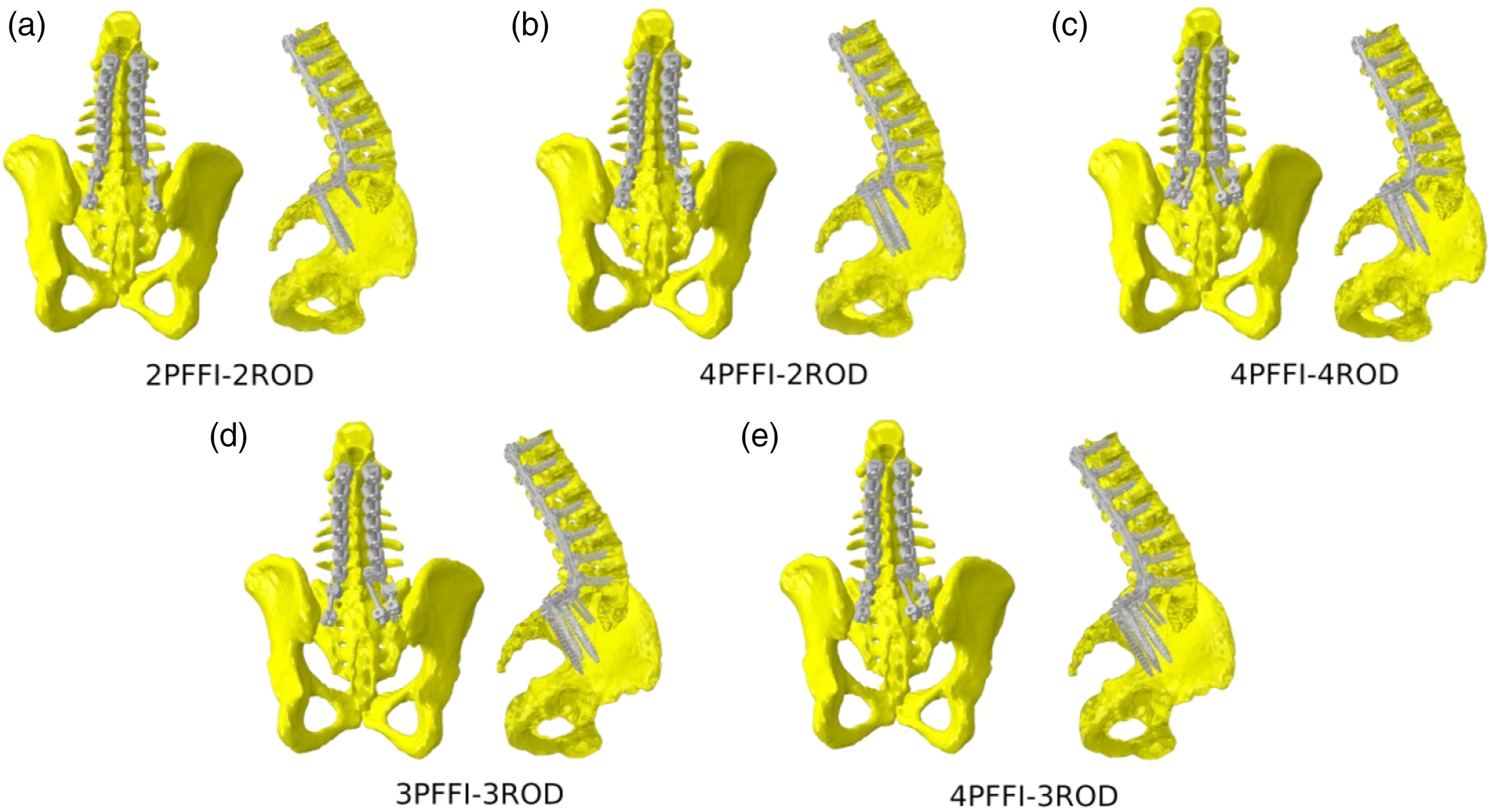
Loading and Boundary Conditions
For all models, pure moments of 7.5 Nm in flexion, extension, left and right lateral bending, and left and right axial rotation were simulated. 21 The moments were applied to the upper endplate of the T10 vertebra through a set of rigid beam elements. Double leg stance was simulated by constraining all nodes belonging to the bilateral acetabula of the finite element models. Therefore, six simulations for each configuration were run resulting in a total of 48 simulations.
Metrics
In order to compare the instrumented configurations, the following variables were calculated: (1) range of motion of L4S1 and of the SIJ; (2) maximal stresses in the S1 pedicle screws; (3) maximal stresses in the posterior rods, including the accessory rods whenever relevant; (4) maximal stresses in the individual PFFI. Each metric was examined in two ways: (1) effect due to the (1) number of implants and (2) number of rods.
Results
Maximum Stresses (MPa) for Left and Right Instrumentation.
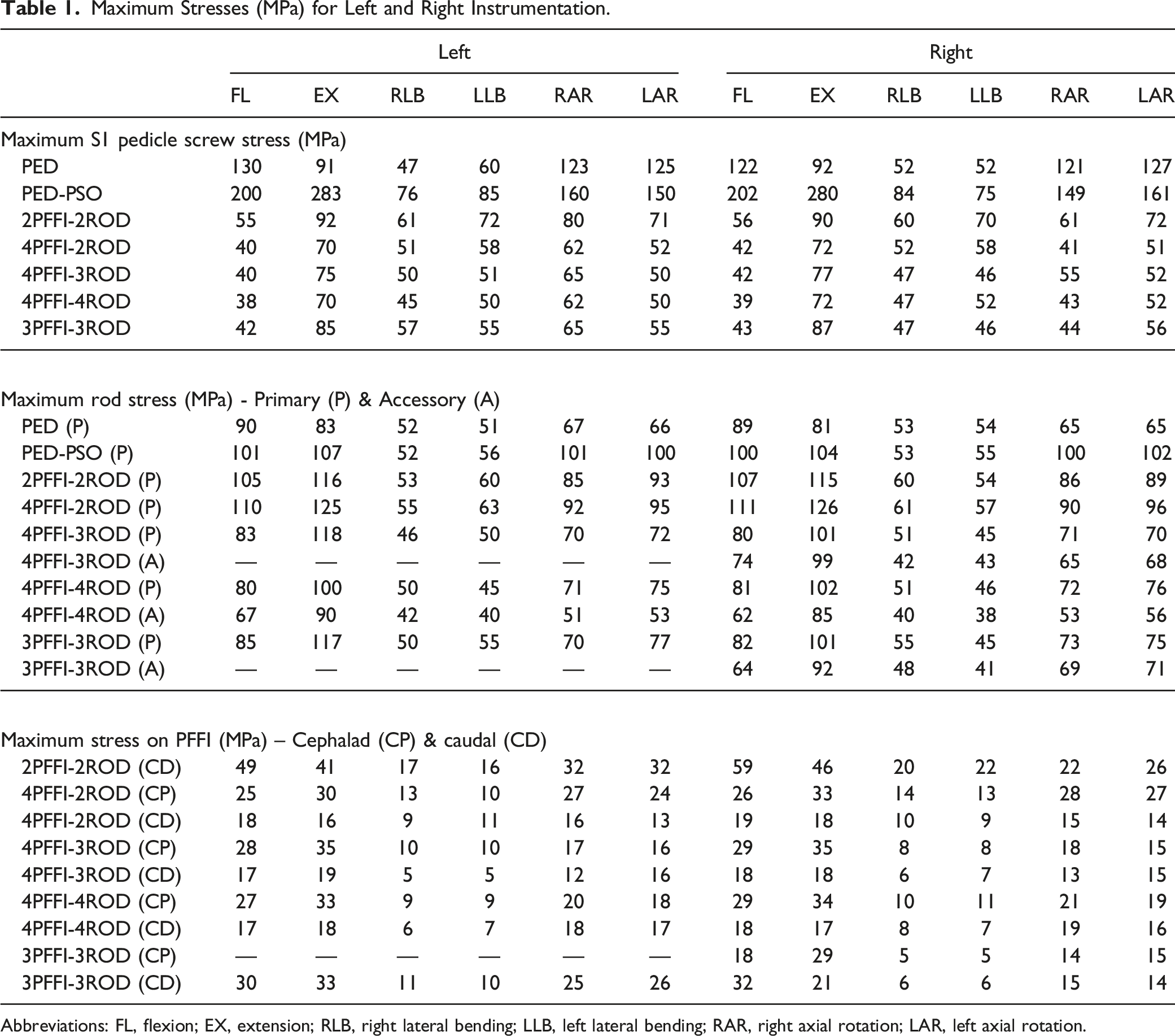
Abbreviations: FL, flexion; EX, extension; RLB, right lateral bending; LLB, left lateral bending; RAR, right axial rotation; LAR, left axial rotation.
Effect of Varying Number of Rods (2 vs 3 vs 4)
L4S1 and SIJ Range of Motion
Inclusion of the L5 PSO resulted in increased range of motion in flexion/extension and lateral bending (Figure 3). When comparing instrumented models with sacropelvic fixation accomplished via four PFFI and two, three, or four rods (4PFFI-2ROD, 4 PFFI-3ROD, and 4PFFI-4ROD, respectively), all demonstrated reduced L4S1 and SIJ ranges of motion relative to PED and PED-PSO (Figure 3(A) and (B)). Reductions among the three configurations were similar with the highest variation in L4S1 motion, .2°, observed in flexion/extension. Reductions in SIJ motion among the three models were similar within any given motion. Effect of varying the number of rods and implants on ranges of motion of the L4S1 region (A and C, respectively) and of the sacroiliac joint (B and D, respectively).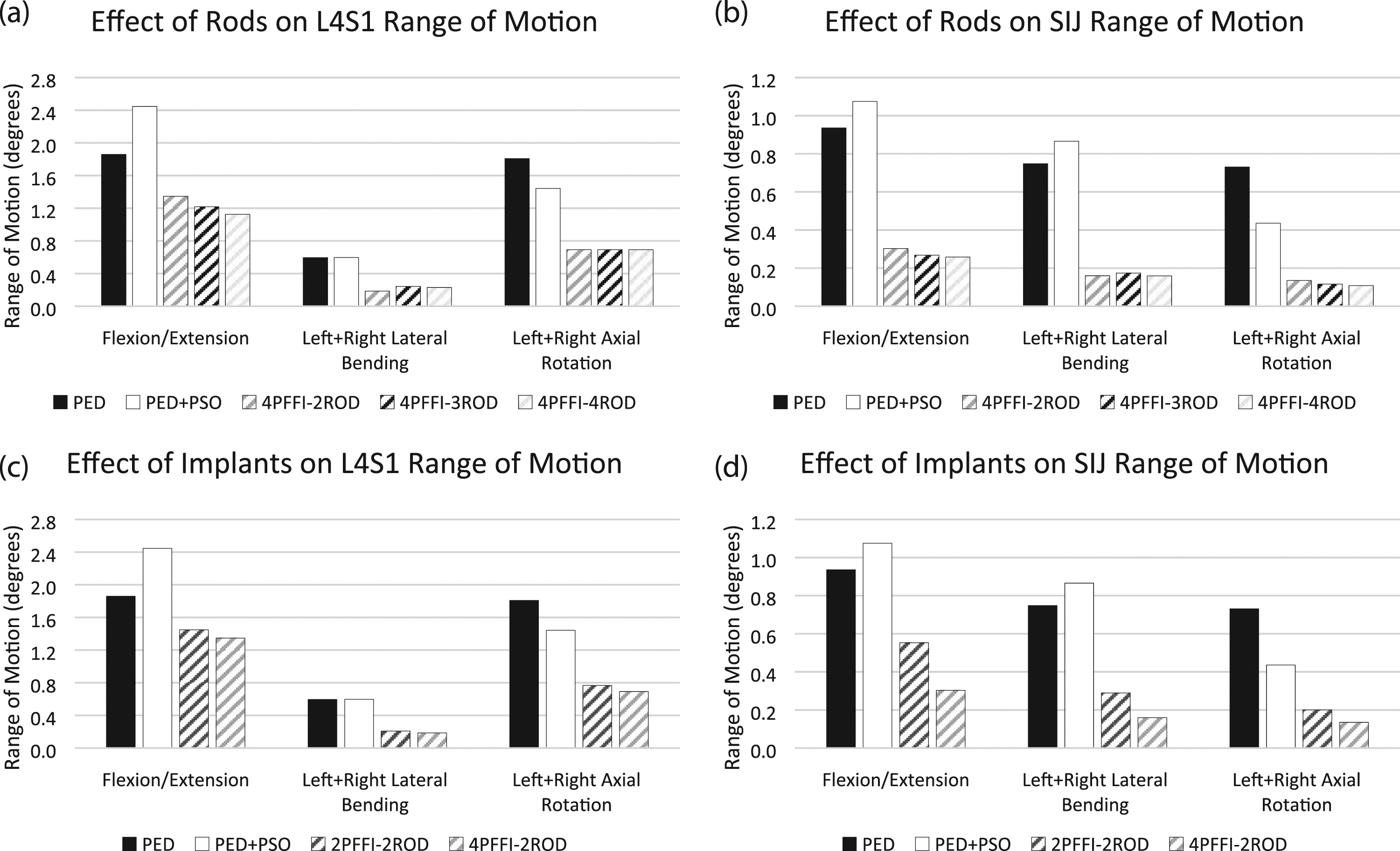
S1 Pedicle Screw Stress
Per Table 1, the addition of the PSO into the PED model (ie, PED-PSO) generally increased the stress on the S1 pedicle screws with a maximal value of 283 MPa calculated in extension. Sacropelvic fixation with four PFFI and two, three, or four rods decreased the stresses to a level near or below the PED model; minimal differences were noted among these configurations in any given motion.
Rod Stress, Primary and Accessory Rods
Relative to PED, inclusion of the PSO resulted in an increase in rod stresses as much as 29%, 10%, and 52% in flexion/extension, lateral bending, and axial rotation, respectively, as well as a shift of the location of maximum stress from the middle of the construct to the level of the PSO (Table 1). Following the addition of sacropelvic fixation, the location of the maximum stress remained the same for all configurations. Rod stress further increased relative to PED-PSO in all motions except in axial rotation for 4PFFI-2ROD; the highest increase was 21% (Figure 4, Table 1). Adding a third (accessory) rod to the construct (ie, 4PFFI-3ROD) generally reduced stresses (as much as 31% in axial rotation) relative to PED-PSO; stresses in the primary rods approached levels observed in PED (Figure 4, Table 1). Maximum stresses in the accessory rod were similar to or less than those observed in the primary rod and carried anywhere from 65%-95% of the maximum stresses observed in the primary rods of PED-PSO. The inclusion of a fourth rod (ie, 4PFFI-4ROD) resulted in similar maximum stresses in the primary rod as those observed for the primary rod in 4PFFI-3ROD (Figure 4, Table 1). The accessory rod, however, had lower maximum stresses than those calculated in the accessory rod of 4PFFI-3ROD (Table 1), and carried between 50%-84% of the maximum stresses calculated in the primary rods of PED-PSO. Percent of maximum rod stress relative to PED-PSO due to varying the number of rods (A – left side; B – right side). Note that in the 4PFFI-3ROD configuration, the accessory rod is placed on the right side.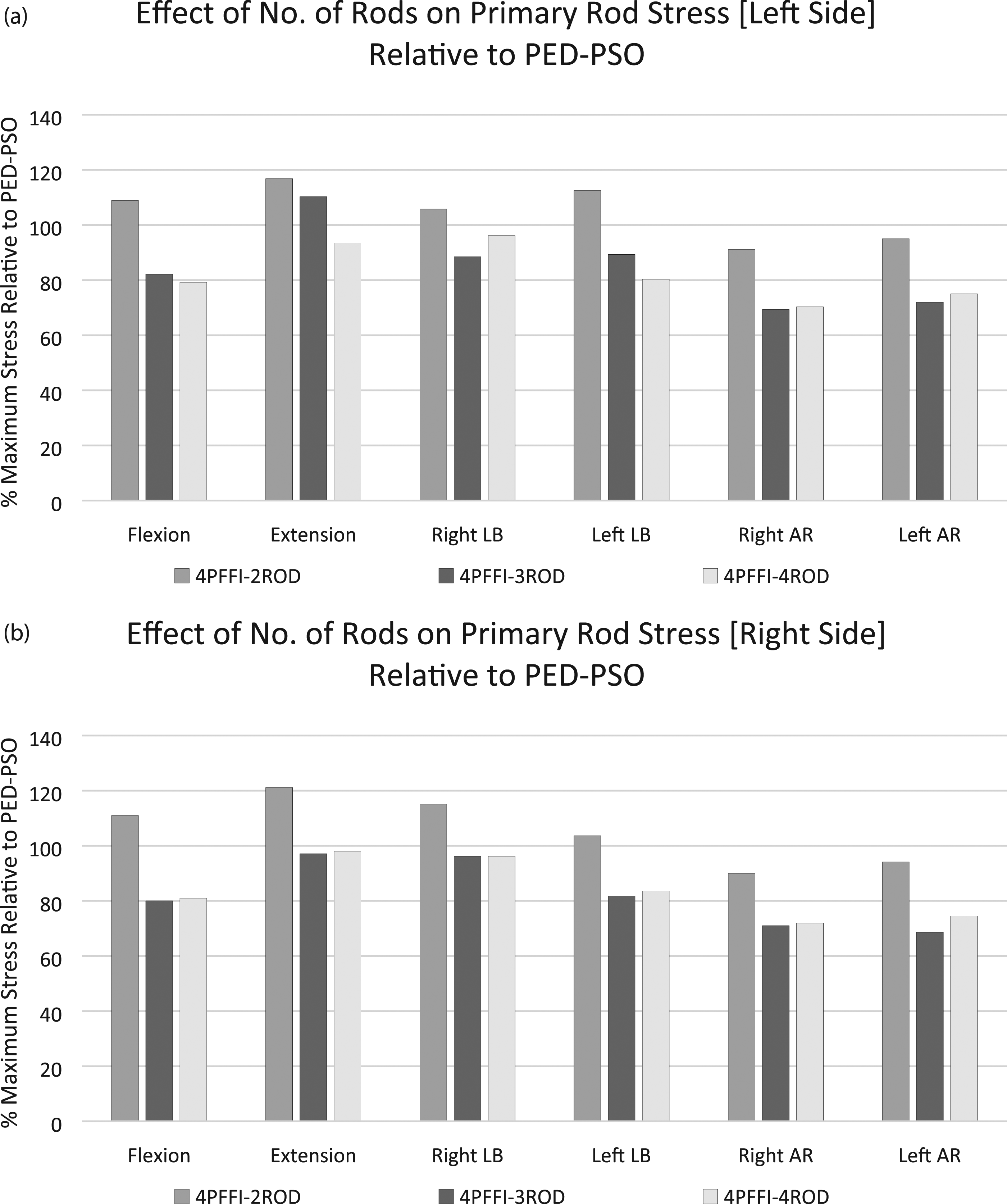
PFFI Stress
The maximal stresses in the PFFI were generally low in all loading conditions, far from the yield stresses of the material (795 MPa 23 ) (Table 1). Maximum stresses varied at most by 12 MPa (left axial rotation, right cephalad PFFI), and the highest stresses (35 MPa) were observed in 4PFFI-3ROD in extension. Generally, implants in the cephalad position had higher stresses than those located caudally.
Effect of Varying Number of Implants (2 vs 4, 3 vs 4)
L4S1 and SIJ Range of Motion
In comparison to PED and PED-PSO, the L4S1 ranges of motion were similar though trended downward with increasing number of PFFI (Figure 3(C)). A more pronounced decreased was noted for SIJ range of motion when the number of PFFI increased (Figure 3(D)).
S1 Pedicle Screw Stress
Inclusion of the PSO in the PED model resulted in an increase in S1 pedicle screw stress regardless of the motion. Following sacropelvic fixation with two or four PFFI and secured with two rods, reductions in stress were noted relative to PED-PSO. When considering 2PFFI-2ROD and 4PFFI-2ROD, four PFFI resulted in lower stresses in all motions (Table 1).
Rod Stress, Primary Rods
Rod stresses increased relative to PED and PED-PSO regardless of the number of implants (two or four PFFI) for flexion, extension, and left/right lateral bending (Table 1). In extension, PED-PSO registered the highest stresses followed by 4PFFI-2ROD, 2PFFI-2ROD, and PED.
PFFI Stress
Flexion and extension resulted in the highest stresses in PFFI for 2PFFI-2ROD. Specifically, a maximum stress of 59 MPa was noted in the right porous fusion/fixation implant in 2PFFI-2ROD in extension. Adding a second PFFI cephalad to this implant (ie, 4PFFI-2ROD) resulted in a decrease in the caudal PFFI stress in all motions (Table 1). When comparing the 3PFFI-3ROD and 4PFFI-3ROD, the unpaired PFFI generally had the highest stresses.
Discussion
As previously stated, PSOs have been shown to be an effective means of correcting sagittal imbalance as they allow for a large local restoration of the lumbar lordosis with good clinical success and a relatively low incidence of biomechanical complications. 6 Lumbar PSO is most commonly performed at L4. 24 Osteotomies at L3 or upper levels are also relatively common, especially in cases of lumbar kyphosis with the apex in the upper lumbar spine. Nevertheless, L4 is generally preferred since most of the physiological lumbar lordosis belongs to the L4-S1 region, and a correction in L4 or below therefore allows for obtaining a more natural and harmonic sagittal profile. 6
Although effective, PSOs can result in complications including pseudarthrosis and instrumentation failure; early reports of PSO in combination with a standard posterior fixation showed instrumentation failure rates up to 39%. 18 To stabilize the osteotomy, posterior instrumentation is extended to levels above and below the PSO. 6 For example, a PSO at L4 leaves two caudal levels available for fixation, ie, L5 and S1, allowing in most cases for a solid fixation without the involvement of the SIJs or pelvis. Several papers describe in vitro8,10,25,26 and finite element models11,12,14,27,28 in which spine specimens with a PSO and concomitant instrumentation were investigated, either by means of standard posterior fixation or with multi-rod constructs. Interestingly, in a study evaluating PSO at L3 and L4 Luca et al 12 calculated stress values in the posterior rods in close agreement with those of the present study, with maximal values in correspondence with the level of the osteotomy under flexion loading, as well as a very similar impact of the use of multi-rod constructs. In an experimental test, La Barbera et al 8 also showed very similar trends in the results, although this study presented strain measurements since the direct quantification of stresses in in vitro tests is not technically feasible.
Though rare in comparison to L3 or L4 PSOs, performing an osteotomy at L5 may be theoretically beneficial in cases of segmental kyphosis at L4-L5. 16 As evidenced by the lack of literature on the topic, further study regarding means of stabilization of the L5 PSO is warranted. Thus, in the current study, multi-rod constructs and sacropelvic fixation with porous/fusion fixation implants were used to stabilize a L5 PSO. To the authors’ knowledge, this is the first biomechanical study in which a PSO was simulated at the L5 level.
Varying the number of rods while keeping the sacropelvic fixation constant (ie, four PFFI) resulted in similar reductions in L4S1 and SIJ ranges of motion among all three configurations relative to PED-PSO and PED. The same observation was true among these configurations when S1 pedicle screw stresses were calculated. Stresses in the sacropelvic implants (PFFI) were generally low and tended to be higher in the cephalad implants than in the caudal implants. However, when rod stresses were examined, it was noted that the addition of one or two accessory rods spanning the PSO (eg, 3- or 4-rod constructs) reduced the stress in the primary rod to levels near the PED model in which no PSO was included. This result suggests that the addition of accessory rods to a high-demand construct offers protection to the primary rods and potentially reduces the risk of rod failure, a finding that is in agreement with previous studies.8,12,25,28
When the number of rods were kept constant, in this case two rods, and the number of PFFI were varied (two vs four), decreases in the L4S1 and SIJ ranges of motion were observed with the latter being more prominent. With regard to the number of PFFI in the construct, increasing the number of implants across the SIJ resulted in decreases in S1 pedicle screw and PFFI stresses. These results collectively suggest an increase in joint stability and a decreased risk of screw breakage when more than two PFFI are implanted below the lumbosacral junction. These results are aligned with previous studies demonstrating the added stability lent by two implants rather than just one across the SI joint.19,20
This study is not without limitations. First, the model is based on the CT scan of a single subject in which a PSO at L5 was simulated though not clinically indicated. The decision to use this model was based on its previous, comprehensive validation19,20 and comparability with existing data including those from our previous studies on sacropelvic fixation. Additionally, starting from an individual anatomical model would have implied obtaining results which depended on the specific pathological and degenerative features, thus hindering generalizability. It should also be noted that the instrumented baseline models, PED and PED-PSO, refer to configurations which would not be optimal from a surgical standpoint, and should be considered as the reference for the comparison of the other constructs rather than as potential alternatives to them. Furthermore, also for the sake of comparability, simplified loading conditions were applied as done in several previous studies12,28 while it is well known that physiological loads are more complex and depend both on muscles and spinal alignment. 29 The baseline finite element model itself includes several simplifications and assumptions which have been discussed elsewhere.19,20 Additionally, given that this FEA study simulates t = 0, it does not consider the effects of fusion that may be attributed to the design of the PFFI. It is reasonable to assume that ranges of motion would be further reduced, suggesting increased joint stability, due to the fusion capability of the PFFI. Also, given that studies on L5 PSOs are rare, direct comparison of the findings from this study with previous investigations was not feasible; however, findings were generally in agreement with other studies utilizing multi-rod constructs and sacropelvic fixation. Finally, while several configurations with posterior instrumentation were explored, interbody stabilization was not simulated despite being documented in several clinical6,30 and biomechanical papers.8,11,31 However, its exclusion was made in efforts to simulate worst case loading on the construct.
In conclusion, the results of this study showed that when a PSO was modelled in L5, the addition of accessory rods reduced stresses on the primary rods within the long construct while multiple sacropelvic implants decreased joint range of motion, particularly for the SIJ. These results suggest a reduced risk of rod breakage and increased joint stability, respectively, when a high-demand construct is utilized for the correction of sagittal imbalance. Such findings would require confirmation via clinical investigation.
Footnotes
Acknowledgments
The study was partially supported by the Italian Ministry of Health (Ricerca Corrente). The authors would like to thank Mr Francois Follini for providing a 3D model of the porous fusion/fixation implant for use in this FEA study.
Declaration of Conflicting Interests
The author(s) declared the following potential conflicts of interest with respect to the research, authorship, and/or publication of this article: RDC, DPL, and SAY are employees of and have stock/stock options in SI-BONE, Inc. DWP is a consultant of SI-BONE, Inc. FG received funding support for this study from SI-BONE, Inc.
Funding
The author(s) received no financial support for the research, authorship, and/or publication of this article.