
Abstract
Study Design
Simulation study.
Objective
Pelvic incidence (PI) should be considered during surgical planning. The ideal patient position with both hip centers perfectly aligned for a lateral radiograph is rarely obtained. It has been suggested that a radiograph with axial and coronal rotation up to 20° is acceptable to obtain a measured PI within 6 degrees of the actual PI. We seek to: (1) evaluate the effect of variations in PI and patient malpositioning on measured vs true PI, and (2) determine whether the presence of one hip center within the bony acetabular rim of the contralateral hip can serve as a simple clinical decision rule on the accuracy of measured PI.
Methods
Published anthropometric three-dimensional pelvic landmark coordinates were used in this study. Radiographic projections were generated using linear algebra for combinations of axial and coronal rotation from −20° to +20°. True and measured PIs were compared.
Results
Rotation to 20° cannot be uniformly accepted as decision rule. Pelvises with higher PIs are more sensitive to malpositioning with greater PI deviation with smaller amounts of rotation. Diagnostic performance of the hip center rule demonstrated a sensitivity of 25.58% and a specificity of 100.00%.
Conclusions
Rather than assessing the quality of radiographs for PI measurement by magnitude of malpositioning, we recommend clinicians use the “hip center rule.” As long as at least one hip center is contained within the bony acetabular rim of the contralateral hip, there is high confidence that measured PI will be within 6° of true PI.
Introduction
The delicate anatomic balance needed to maintain efficient posture is strongly influenced by pelvic incidence (PI).1-3 Consequently, matching sagittal alignment to PI is an important surgical consideration that influences patient reported outcomes and the incidence of several post-operative complications.4-6 As there is great variation in PI, it is crucial that surgeons measure this parameter accurately. 7
It may be difficult to obtain a perfect lateral radiograph for PI measurement because of challenges in clinically identifying a patient’s pelvic landmarks by radiology technicians and limb length discrepancy, and native pelvic obliquity. It has previously been suggested that measured PI may be inaccurate if the patient is malpositioned in the axial or coronal plane by over 20°.8-11 These findings are not generalizable because the normal range of physiologic PIs, bidirectional rotation (clockwise and counter-clockwise), and two-plane malpositioning (combined axial and coronal rotation) were not studied. Furthermore, previous work is difficult to apply in a clinical setting because a practical decision rule to assess the quality of a radiograph for measuring PI has not been proposed.
The objectives of this study are 2-fold. The first is to systematically evaluate the accuracy of measured PI over (i) a range of physiologic PIs, and under (ii) bidirectional rotation, and (iii) two-plane malpositioning. The second is to develop a simple clinical decision making rule for predicting PI accuracy based on the degree of hip overlap. We hypothesize that the PI deviation will be within the acceptable range of 6° as long as at least one hip center is contained within the bony acetabular rim of the contralateral hip.
Methods
Overview
This study utilizes publicly available three-dimensional pelvic coordinates. Algebraically, we project 3D pelvic coordinates onto a 2D X-ray plate. The measured PI is then measured, as well as the locations of the hip centers. These calculations are repeated for combinations of coronal and axial rotation up to 20° in .25° increments. This algorithm yields a total number of 25 921 simulations which are used to calculate the sensitivity and specificity of accurately measuring the PI based on the positive hip center rule.
Data
Data from the United States Highway Traffic Safety Administration and Federal Aviation Administration were used for this study. 12 This dataset contains the mean three-dimensional (3D) coordinates on 1419 adult male anatomic specimens of average height (between the 25th and 75th percentiles with mean height and weight 173.7 cm and 74.8 kg, respectively). Bony surface landmarks on the sacrum, sacroiliac joints, acetabulum, and ilia were digitized using a diagraph with a mean accuracy of ±0.5 mm. This dataset contains the most complete spatial data on the human pelvic and has been used to develop several anthropometric test devices or “crash test dummies.”12-14
For this study, we generalized these data to the 6 morphologic groups based on PI described by Barrey et al.
1
These groups are important because the apex and inflection point of lumbar lordosis varies with group. To adjust the PI of the 3D data, the innominate bone was rotated through the SI joint about an axis passing through the midpoint of the middle of the S1 superior endplate to achieve a PI corresponding to each of the 6 morphologic groups (Figure 1). The pelvic thickness was adjusted for PI applying a Pearson correlation coefficient of −.37°/mm.
15
To model the S1 superior endplate in detail, we applied the morphometric data reported by Hall et al. on the shape of the S1 endplate.
16
Technique for modifying the PI for a given set of pelvic landmark coordinates. The red axis is the mid-sagittal plane. The blue axis is perpendicular to the S1 superior endplate. The green axis lies on the surface of the superior S1 endplate and passes through the midpoint. In panels (A)–(F), the sacrum is fixed in 3D space. 3D landmarks for 6 different PIs were generated by rotating the innominate bones through the SI joints around the green axis.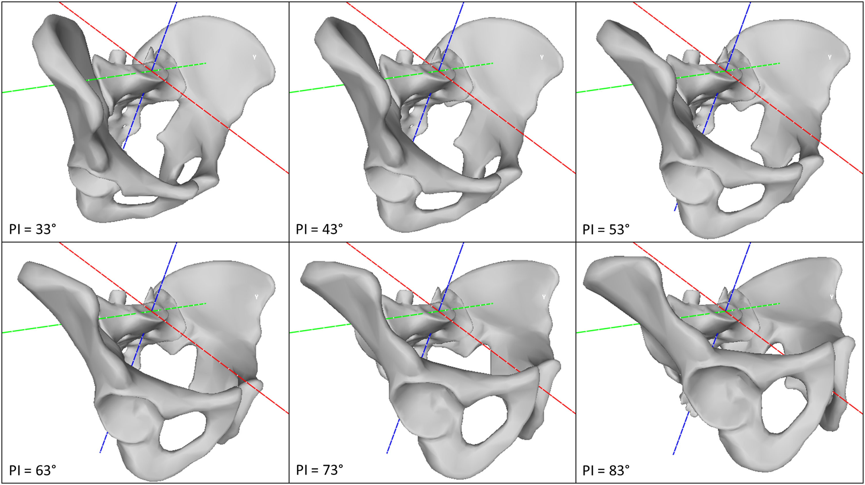
Radiograph Projection – Geometric Model
Pelvic landmark positions on a lateral radiograph image were determined by projecting 3D pelvic landmarks onto a 2D X-ray image receptor. A tube-to-receptor distance of 100 cm was used. The image receptor abutted the most leftward 3D pelvic landmark. The X-ray tube was directed from right to left and the center of the tube is positioned at the top of the iliac crests and antero-posteriorly at the center of the S1 superior endplate (Figure 2).
17
The PI was calculated using linear algebra (Supplementary File 1) and the following projected 2D coordinates: (i) midpoint of the hip centers, (ii) most anterior point on superior S1 endplate, and (iii) most posterior point on the superior S1 endplate. Graphical explanation of X-ray projection technique. The blue plane represents the X-ray cassette which abuts the most leftward point on the left hemi-pelvis. The cone represents X-rays originating from a tube (point source) 100 cm to the right of X-ray cassette. The red dot represents the most posterior point on S1 superior endplate, the purple dot represents most anterior point on the superior S1 endplate, the blue dot represents the right hip center and the orange dot represents the left hip center. The location of these landmarks on the X-ray cassette is shown in using a dot of the same color.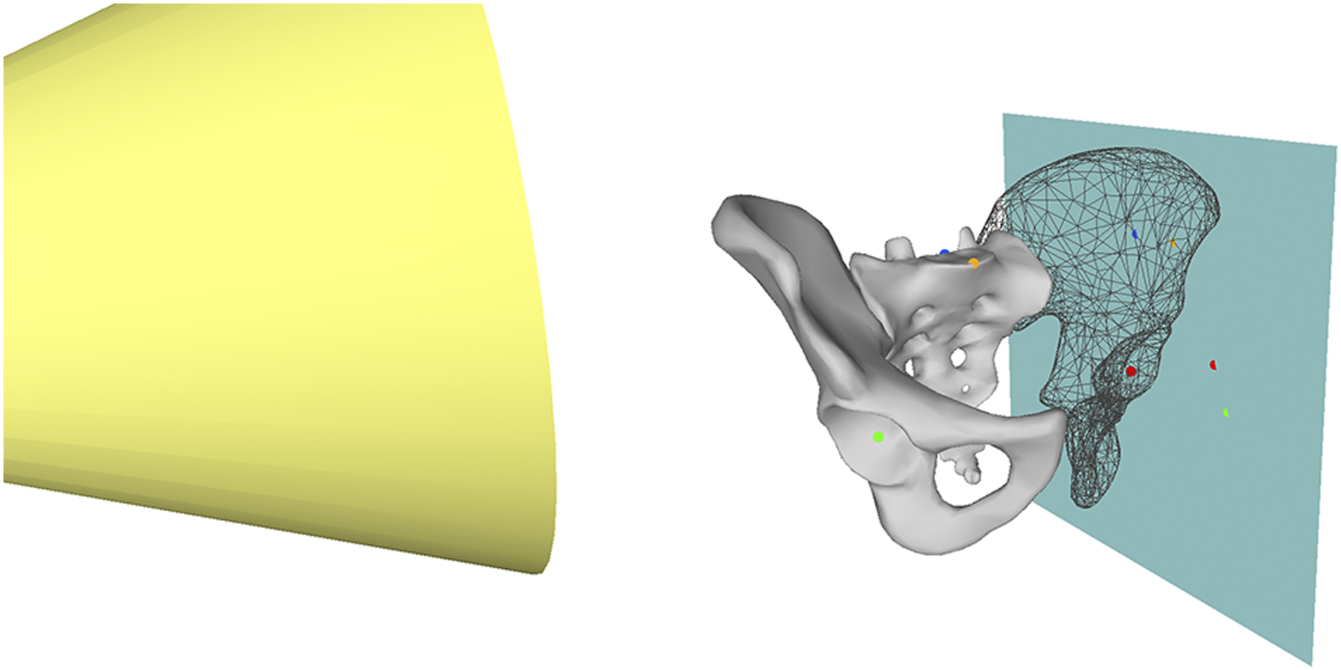
Impact of Rotation – Geometric Model
A geometric model was developed using standard linear algebra techniques to study the impact of all combinations of axial and coronal rotation from −20° to 20° on PI (Supplementary File 2). 3D pelvic landmark coordinates were rotated to new positions using the techniques described in the text in Supplementary File 1 prior to X-ray projection. Our model is consistent with standard geometric conventions with positive rotations to the left and negative rotations to the right.
It is important to consider that the projected shape of the superior S1 endplate changes with rotation. In a true lateral radiograph, the most anterior point on the S1 endplate is the sacral promontory. However, with axial rotation to the right, the most anterior point will instead be a point on the left half of the endplate (Supplementary File 3). Due to magnification, the X-ray projection of the superior endplate is not a simple line (Supplementary File 4). To adjust for this distortion, the first principal component of the X-ray projection was identified as the “best fit” line for the S1 endplate. In cases of orthographic projection without magnification, such as the CT scout image or an image obtained using slot scanning technology, the first principal component corresponds to the undistorted superior S1 endplate (Supplementary File 4). Therefore, the line perpendicular to the first principal component that passed through the midpoint of the projected superior S1 endplate was used for PI calculation.
Validation of Geometric Model
Validity of radiographic projections was assessed by comparing the measured PIs obtained from radiographic projections with 0° to 20° of axial rotation to those reported by Tyrakowski et al. 8 and Jin et al. 9 and with 0° to 20° of coronal rotation to those reported by Janusz et al. 11 Mean error and mean absolute error were −2.29o and +2.1o and accurate with a mean absolute error between 1.6o and 3.04o for predicting the results of these studies. These results indicate that the geometric model was valid and was used to proceed with analysis.
Statistical Analysis
PI deviation, the difference between the true anatomical PI and measured PI, was calculated with each combination of axial and coronal rotation. We classified PI deviation as acceptable if it was less than +6° or greater than −6°, that is, measured PI within ±6° of true PI. This threshold was chosen because it is the upper limit of published inter-rater and intra-rater reproducibility of PI measurement.18–20 Acceptability of PI deviation was also plotted.
For each radiographic projection, we determined whether at least one hip center was contained within the bony acetabular rim of the contralateral hip, which we define as a “positive hip center rule.” We then calculated the sensitivity and specificity of the “positive hip center rule” for diagnosing acceptable PI deviation. 21 The confusion matrices were generated using prevalence weights for the 6 morphologic pelvic types based on Barrey’s et al.’s work. 2 The prevalence was 9% PI 28°–38°, 18% PI 38°–48°, 44% PI 48°–58°, 19% PI 58°–68°, 8% PI 68°–78°, 2% PI >88°.
Results
The relationship between PI deviation, axial rotation, and coronal rotation is shown in Figure 3. The area with unacceptable PI deviation (measured PI not within ±6° of the true PI) is identified in these figures as the gray shaded area. The proportion of each plot with acceptable PI deviation (measured PI within ±6° of the true PI) is quantified in Figure 3. Higher true PIs had smaller areas with acceptable PI deviation (Figure 3), and this is reflected in Figure 3 as a larger area of the plot shaded in dark. This indicates that pelvises with higher true PIs are more sensitive to axial and coronal rotation. Figure 3 indicates that it is possible to have unacceptable PI deviation with less than 20° of axial and/or coronal rotation in either direction. The relationship between PI deviation and rotation varies with true PI and pelvis size. PI deviation for PIs listed in the title of each plot. Positive rotation is leftward; negative rotation is rightward; x-axis is axial rotation; and y-axis is coronal rotation. The area with unacceptable PI deviation (measured PI not within ±6° of the true PI) is the gray shaded area. The region within the dashed circle contains combinations of axial and coronal rotation in which at least 1 hip center is contained within the bony acetabular rim of the contralateral hip, indicating a “positive hip center rule.” Plot area with acceptable PI deviation: 87%, 89%, 89%, 85%, 80%, and 75%. PI, pelvic incidence.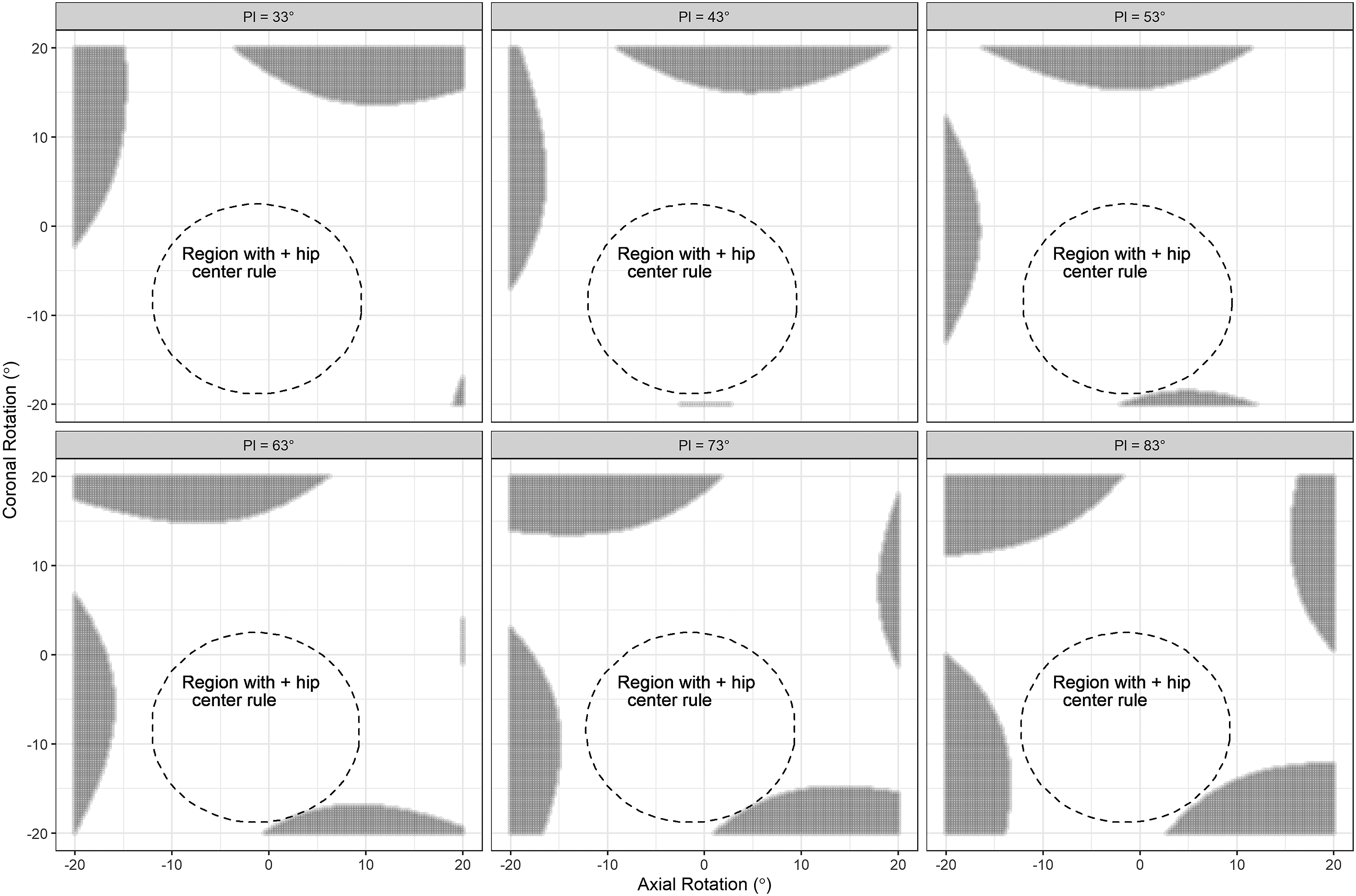
In Figure 3, the region within the dashed circle contains combinations of axial and coronal rotation in which at least one hip center is contained within the bony acetabular rim of the contralateral hip, indicating a “positive hip center rule.” This area is biased to negative (rightward) coronal rotation to magnification caused by X-rays traveling from left to right.
We assessed diagnostic performance of the hip center rule for diagnosing a measured PI within ±6° of true PI by evaluating the confusion matrix for each point evaluated in Figure 3. A positive hip center rule is when one hip center is contained within the bony acetabular rim of the contralateral hip. The confusion matrix is shown in Supplementary File 5, which indicates the hip center rule demonstrated a sensitivity of 25.58% and a specificity of 100.00%.
Discussion
Pelvic incidence, PI, is an important determinant of a patient’s normal sagittal alignment.2,22,23 We have quantified the accuracy of PI measurement in the presence of combined axial and coronal rotation for different pelvis sizes across a range of physiologic true PIs. We also propose a simple rule that can be used to assess the quality of radiographs used for measuring PI.
Our first objective was to evaluate the accuracy of measured PI under a wider set of conditions than previously reported.8-11 Four papers have been published on the accuracy of PI measurement with patient malpositioning. Tyrakowski et al. 8 studied the accuracy of PI under 0° to 45° of rightward axial rotation using a radiological pelvic phantom with an X-ray tube to the cassette distance of 100 cm centered on the center of the pelvis. They found PI becomes unreliable above 30° of rotation. Jin et al. 9 studied the accuracy of PI under 0° to 30° of leftward axial rotation using digitally reconstructed radiographs from 20 healthy participants with an unspecified X-ray tube to cassette distance and unspecified centering. They found PI becomes unreliable above 17.5° of rotation. Li et al. 10 studied the accuracy of PI under 0° to 30° of leftward axial rotation using a cadaveric specimen with an X-ray tube to the cassette distance of 50 cm with unspecified centering. They found PI becomes unreliable above 25° of rotation. Janusz et al. 11 studied the accuracy of PI under 0° to 45° of leftward coronal rotation using a radiological pelvic phantom with an X-ray tube to the cassette distance of 100 cm centered on the center of the pelvis. They found PI becomes unreliable above 20° of rotation. Synthesizing this literature, measured PI may be inaccurate if the patient is malpositioned in either the axial or coronal plane by approximately 20° but the specific threshold varies by the X-ray technique. We found that pelvises with higher PIs are more sensitive to malrotation. Figure 3 demonstrates that although 20° malrotation may be acceptable in many cases,8-11 the relationship is complex and the is threshold is not generalizable.
Out second objective was to evaluate whether the hip center rule could be used to quickly assess the quality of radiographs for PI measurement. We hypothesized that PI could be measured accurately as long as at least 1 hip center is contained within the bony acetabular rim of the contralateral hip. We were motivated to do this because decision rules proposed in previous work required use of cumbersome mathematical equations.8-11 An example of the hip center rule is shown in Figure 4 which is 100% specific. Accordingly, a “negative” hip center rule does not mean that measured PI is inaccurate. However, we have high confidence that measured PI is accurate within ±6° of true PI when the hip center rule is “positive.” This is reflected in the fact that the “positive” hip center rule regions in Figure 3 had minimal to no overlap with the gray shaded regions. Example of the hip center rule. (A) True PI measured from perfect lateral radiograph with hip centers superimposed. (B) PI measured from radiograph with hip center contained within the bony acetabulum of the contralateral hip that is within 6° of true PI. (C) PI measured from radiograph with no hip overlap demonstrating unacceptable deviation from true PI. This represents rotation that is inappropriate for analysis of sagittal balance. PI, pelvic incidence.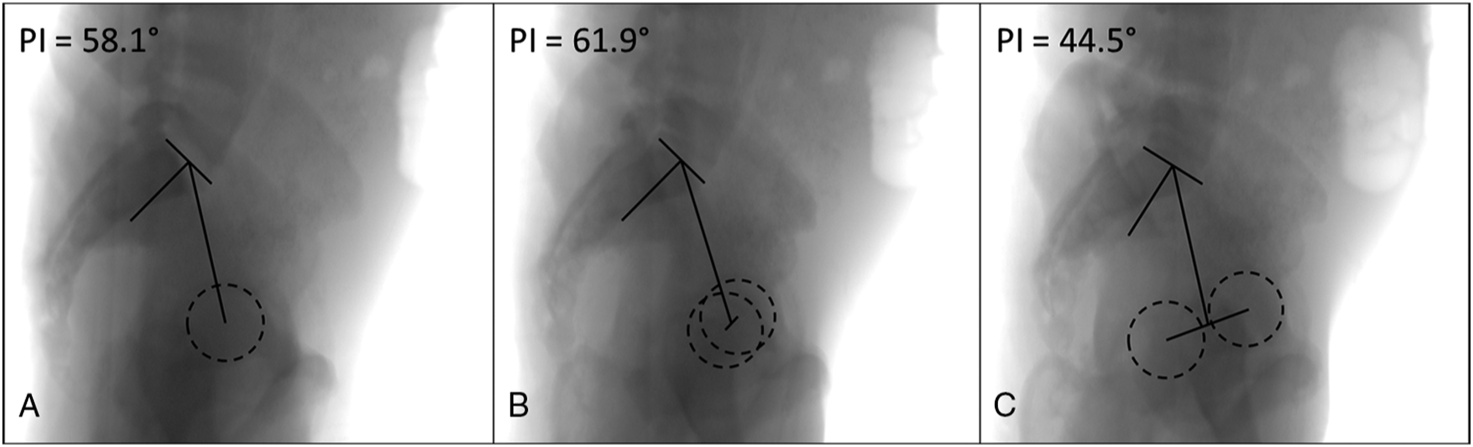
Our study is unique in that we used geometric modeling to generate radiographic projections. Our model was well calibrated as it reproduced results reported in previously published studies on this topic.9,11 Use of a geometric model allowed us to study PI deviation in a more generalizable fashion without exposing patients to unnecessary radiation. Geometric modeling is a resource-efficient and useful technique that could be applied for other anatomic areas and topics.
There are 3 weaknesses of this study that should be noted. First, our geometric model did not account for a soft tissue envelope: this could underestimate the amount of magnification distortion seen in large patients. Secondly, our analysis is limited to males of average height (between the 25th and 75th percentiles) which does not exhaustively capture the entire population. Thirdly, our geometric model assumes accurate and reproducible identification of radiographic landmarks by clinicians. Fortunately these weaknesses could be addressed in a follow-up study using real clinical images.
Conclusions
We demonstrated that axial and coronal rotations do interact and potentially lead to inaccuracies in measured PI. We have validated a simple decision rule that allows clinicians to quickly access the quality of radiographs for PI measurement. An accurate estimate of PI is needed to understand normal sagittal alignment and morphology for a given patient which in turn is required for planning surgery that maximizes patient outcomes and minimizes post-operative complications.4-6 As long as at least 1 hip center is contained within the bony acetabular rim of the contralateral hip, clinicians can be 100% confident that measured PI will be within ±6° of true PI. Since this study was conducted using a geometric model, this decision rule should be further validated using clinical images.
Supplemental Material
sj-pdf-1-gsj-10.1177_21925682211049734 – Supplemental Material for The Hip Center Rule Can be Used to Decide if Measured Pelvic Incidence is Accurate
Supplemental Material, sj-pdf-1-gsj-10.1177_21925682211049734 for The Hip Center Rule Can be Used to Decide if Measured Pelvic Incidence is Accurate by Felicity Fisk, Colby Oitment, Kevin Taliaferro and Markian A. Pahuta in Global Spine Journal
Supplemental Material
sj-tiff-2-gsj-10.1177_21925682211049734 – Supplemental Material for The Hip Center Rule Can be Used to Decide if Measured Pelvic Incidence is Accurate
Supplemental Material, sj-tiff-2-gsj-10.1177_21925682211049734 for The Hip Center Rule Can be Used to Decide if Measured Pelvic Incidence is Accurate by Felicity Fisk, Colby Oitment, Kevin Taliaferro and Markian A. Pahuta in Global Spine Journal
Supplemental Material
sj-tiff-3-gsj-10.1177_21925682211049734 – Supplemental Material for The Hip Center Rule Can be Used to Decide if Measured Pelvic Incidence is Accurate
Supplemental Material, sj-tiff-3-gsj-10.1177_21925682211049734 for The Hip Center Rule Can be Used to Decide if Measured Pelvic Incidence is Accurate by Felicity Fisk, Colby Oitment, Kevin Taliaferro and Markian A. Pahuta in Global Spine Journal
Supplemental Material
sj-tiff-4-gsj-10.1177_21925682211049734 – Supplemental Material for The Hip Center Rule Can be Used to Decide if Measured Pelvic Incidence is Accurate
Supplemental Material, sj-tiff-4-gsj-10.1177_21925682211049734 for The Hip Center Rule Can be Used to Decide if Measured Pelvic Incidence is Accurate by Felicity Fisk, Colby Oitment, Kevin Taliaferro and Markian A. Pahuta in Global Spine Journal
Supplemental Material
sj-pdf-5-gsj-10.1177_21925682211049734 – Supplemental Material for The Hip Center Rule Can be Used to Decide if Measured Pelvic Incidence is Accurate
Supplemental Material, sj-pdf-5-gsj-10.1177_21925682211049734 for The Hip Center Rule Can be Used to Decide if Measured Pelvic Incidence is Accurate by Felicity Fisk, Colby Oitment, Kevin Taliaferro and Markian A. Pahuta in Global Spine Journal
Footnotes
Declaration of Conflicting Interests
The author(s) declared no potential conflicts of interest with respect to the research, authorship, and/or publication of this article.
Funding
The author(s) received no financial support for the research, authorship, and/or publication of this article.
Supplemental Material
Supplemental material for this article is available online.
References
Supplementary Material
Please find the following supplemental material available below.
For Open Access articles published under a Creative Commons License, all supplemental material carries the same license as the article it is associated with.
For non-Open Access articles published, all supplemental material carries a non-exclusive license, and permission requests for re-use of supplemental material or any part of supplemental material shall be sent directly to the copyright owner as specified in the copyright notice associated with the article.