
Abstract
The ability to grasp objects has a significant impact on the independence of individuals following a stroke, a spinal cord injury, or for those who are living with amyotrophic lateral sclerosis. In most cases, physical rehabilitation is not sufficient to regain the hand function necessary for day-to-day life. Hand orthoses capable of providing grasping assistance in activities of daily living are therefore crucial to a more independent lifestyle. However, most available options struggle to offer an acceptable balance between cost, size, weight and functionality, resulting in limited use in practice. This article presents a low-cost, 3D-printed hand orthosis that relies solely on mechanical elements to aid in finger flexion. An underactuated, flexible design for the fingers with nylon strips as spring blades was used to achieve a design that costs only 27% of the price of comparable commercially available options, as well as being very lightweight and easily customizable. It was also demonstrated that rigid thumb supports allowed the orthosis to be used in the majority of daily grasping tasks. Finally, the use of the proposed mechanism was shown to be able to provide up to 4 N of flexion assistance to the finger when using a medium wrap grip.
Keywords
Introduction
Most activities of daily living (ADL), such as preparing food, transportation or getting dressed, require grasping an object with a hand. 1 The ability to execute these tasks independently is therefore significantly decreased for people with limited use of their wrists and fingers. 2 This most strongly affects individuals living with a spinal cord injury (SCI), 3 people living with amyotrophic lateral sclerosis (ALS) 4 and stroke survivors,5,6 who together account for approximately 110 million people worldwide.3–6
The go-to method to remedy the lack of strength and dexterity in the wrist and hand is to undergo physical rehabilitation with the objective of gaining back some abilities. 7 However, this approach has a limit inherent to each individual, and does not lead to a complete rehabilitation in many cases.8–10 For this reason, many hand orthoses have been developed, 11 and some were commercialized.
The commercial solutions range from a simple Velcro® glove meant to secure the hand to an object and costing $93 12 to smart, motorized orthoses costing upwards of $9,000.13–15 The less expensive options offer very little in terms of functionality and usability in daily life, while the price of the more costly alternatives is prohibitive for many potential users. In fact, the principal limit to assistive technology is the cost, as found in the 2022 Canadian Survey on Disability, which found that 32.2% of people with milder disabilities had unmet needs for either assistive aids, devices or technologies, prescription medication, or health care therapies and services due to cost. This number increases to 52.8% for people with more severe disabilities. 16 Besides, the authors have consulted a group of forty occupational therapists who found that the available options are not used in practice. 17 There is therefore a strong need for new, low-cost assistive aids.
The hand orthoses developed in the scientific literature can be split into three main categories: rigid, soft and, increasingly popular, flexible orthoses. Soft mechanisms based on tendons are lighter and smaller, but allow less control on the applied forces, since the user’s fingers are a necessary part of the mechanism, which can create risks for the user. Rigid mechanisms are usually larger and heavier, but allow a better control of the applied forces and their direction, since the user’s fingers are not directly involved in the mechanism, making them safer for users. 18 Flexible mechanisms combine features from rigid and soft mechanisms.
Most state-of-the-art hand orthoses in all three categories are motorized. Some tendon-based options include the orthosis developed by Yoo et al., 19 which assists finger flexion using a linear motor to pull cables attached to rings situated around each phalange. Park and Park 20 used a similar concept, but opted for a partially flexible structure on the palmar side of the actuated fingers, which allows the orthosis to passively assist finger extension but significantly reduces tactile feedback. Chen et al. 21 opted to assist finger extension, by placing tendons on the dorsal side of the hand, leaving the palmar side mostly free. However, tendon-driven mechanisms can only actively assist finger flexion or extension, even with motorized orthoses and those assisting flexion need to be placed on the palmar side of the hand, which hinders tactile feedback.
A rigid orthosis has been developed by Chang et al., 22 which has a similar working principle to the Powergrip, 14 with the addition of a four-bar mechanism. It was deemed too big and too heavy to be worn all day by potential users, and could not be put on independently by them, which they felt was necessary.
Arata et al. 23 opted for a flexible orthosis and developed an underactuated finger with a three spring system, capable of mimicking the natural bending motion of a human finger. They refined their design in Bützer et al. 24 with the addition of an actuated thumb and a more compact look. Li et al. 25 built upon this design by introducing non-parallel fingers for increased stiffness and output fingertip force. Those designs are extremely promising, but being motorized, present some challenges in terms of portability with the need to carry actuation units and power supplies. They are also inherently more expensive than a fully mechanical version would be.
Fully mechanical orthoses are less common than their motorized counterparts, but still present in literature. Chen and Lum 26 presented a spring-based rigid orthosis capable of assisting finger extension. Portnova et al. 27 also opted for a rigid mechanism, and presented a 3D printed wrist-driven orthosis based on the tenodesis mechanism. Both orthoses, using rigid mechanisms, are quite bulky, which reduces the likelihood of them being worn all day by users. Kim et al. 28 proposed a fully mechanical soft orthosis with tendons used to perform a tripod grasp. This orthosis is less bulky that the others presented, but requires the use of the second hand to activate the mechanism, making two-handed grasps impossible.
The contribution of this article is further work on flexible orthoses by presenting a fully mechanical, flexible orthosis capable of assisting finger flexion. The orthosis is lightweight and, by virtue of most components being 3D-printed, easily customizable and extremely low cost.
The article first presents the design process of the orthosis, in terms of the design requirements, the design of the underactuated fingers, the tenodesis mechanism and the thumb support. The results of the testing are then presented. The next section is the discussion of the article. The last section presents a conclusion.
Design
Design requirements
The specific design requirements for each individual user can vary greatly, depending on many factors such as spasticity, contractures, muscle tone or whether they need assistance for finger extension or flexion,29,30 However, since the functionality required to perform ADL is similar across all users, it remains possible to determine some common design requirements for most users.
Since most potential users will already be familiar with the tenodesis grasp, we have decided to design a mechanism that would use this movement as a starting point and amplify its natural grasping force. As other orthoses do,19,27,28 the proposed orthosis will provide assistance in flexion, but not in extension.
A review of the relevant literature, as well as discussions with occupational therapists have led to the elaboration of the following design requirements. Grasp force
Sufficient to lift objects up to 500 g (for example, a 500 mL water bottle), around 5 N. This value represents approximately half of the target value for motorized orthoses.24,25 Resistance
The mechanism should withstand forces up to 40 N without breaking. Size and weight
The device should be small and lightweight so as to not restrict the user’s movement. A maximum weight of 200 g and a size of 5 cm × 5 cm x 3 cm on the back of the hand were the limits found by subjects with hand impairments.
30
Tactile feedback
The palmar side of the hand and fingers should remain as free as possible, to maintain tactile feedback. Ease of installation
The user should be able to don the device independently in a few seconds. Ease of cleaning
Designed for easy surface cleaning. Waterproof
The device should have sufficient water resistance to allow the user to wash their hands without having to take it off. Cost
The cost should be minimized to improve the accessibility of the device. (≤$100).
Underactuated fingers
The basis of our underactuated flexible finger design was first presented by Arata et al.,
23
who then refined their own design in Bützer et al.,
24
before being used as a starting point by Li et al.
25
The device proposed by Li et al. builds upon the flexible hand exoskeleton designed by Bützer et al. to show that a converging finger design achieves greater stiffness than one that is parallel. In turn, this leads to a higher fingertip force. Figure 1 illustrates the differences between parallel and converging designs, as well as some key parameters for the latter. Our proposed finger design follows a converging concept, using a two-layer spring mechanism with four rigid sections. The first section represents the metacarpal and is fixed to the top of the hand, while the other three sections represent the proximal, medial and distal phalanges, respectively. The lower spring is fixed to all four rigid sections, while the upper spring is only fixed to the distal phalange. This allows an axial force applied on the upper spring to create the bending motion of the finger. The following values were used for the parameters shown in Figure 1: angle = 2.44
o
, d1 = 93 mm and d2 = 7.38 mm. Illustration of parallel and converging finger designs.
While both Bützer et al. and Li et al. use metallic spring blades in their finger designs, in the interest of keeping our device both lightweight and low cost, we explored the use of cable ties (tie-wraps), as a fatigue resistant, readily available material. The cable ties proved to be a viable alternative to metallic spring blades, with the advantage of needing less input force to generate movement, which is especially important since our orthosis will be powered by the users wrist and not a motor. However, their lower stiffness makes cable ties more prone to buckling, which proved to be an issue in our case.
To counteract this, we tested three different geometries, which we compared qualitatively to the original in terms of buckling and output fingertip force. (Figure 3(a)) shows how buckling occurred in the original design. Since the weakest point of the design is the flexible section between the first two rigid sections, the focus was put on reducing buckling in this specific area.
The different geometries that were tested are (illustrated in Figure 2). 1. Original 20 mm proximal phalange. 2. Shorter proximal phalange 15 mm proximal phalange, to increase the distance between the proximal and medial phalanges, easing the sliding motion of the spring and reducing buckling between the metacarpal and the proximal phalange. 3. 5 mm supports 5 mm supports on the top of the proximal phalange and the metacarpal. 4. 10 mm supports 10 mm supports on the top of the proximal phalange and the metacarpal. CAD drawings of the different finger geometries tested to reduce buckling.

Figure 3 shows how all the different geometries were able to resist buckling. The shorter proximal phalange had little to no effect on the buckling as illustrated in (Figure 3(b)), but the addition of supports had a much more significant effect. The 5 mm supports did resolve the issue of buckling between the first and second rigid sections, but induced buckling between the second and third rigid sections. The most successful geometry was therefore the 10 mm supports, which improved the original buckling issue, while introducing only minimal buckling between the second and third rigid sections. To further improve the buckling resistance of our underactuated fingers, as well as having better control of the size and length of the spring blades, different thickness of nylon 66, the same material used for tie wraps, were also tested. Qualitative buckling experiment results for (a) the original design, (b) a reduced length for the proximal phalange, (c) 5 mm supports and (d) 10 mm supoports on the metacarple and the proximal phalange.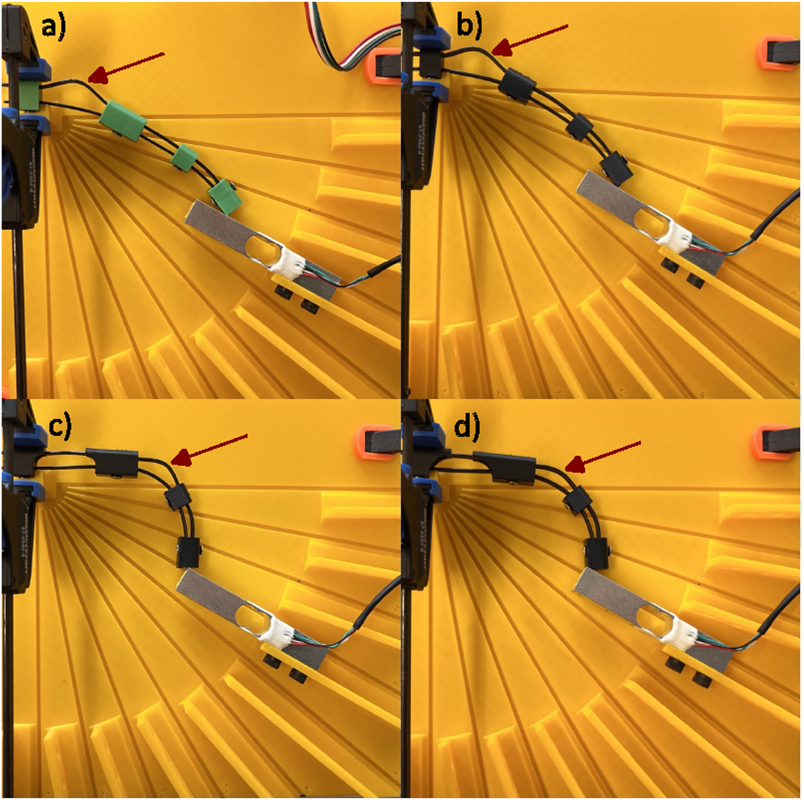
Another important feature of the underactuated flexible fingers is their inherent compliance; if any of the rigid sections are blocked, the motion will automatically continue in the remaining free sections. This is shown in Figure 4, where the first, second and third rigid sections of the finger, respectively, have been blocked. If the first or second sections are blocked, the finger can fully override the blocked section and continue its bending motion. However, in the case of the third rigid section being blocked, the rigidity of the finger is too high to allow bending to occur only in the last flexible section, leading to incomplete compliance. Using spring blades with lower rigidity would improve the compliance of the finger, at the cost of a reduction in the output fingertip force, which is why that solution was not chosen for our device. Compliance of the final finger geometry. The compliance of the finger is shown for situations where the first (left), second (middle) and third (right) rigid sections are blocked.
Tenodesis mechanism
The mechanism of the proposed orthosis is based on the tenodesis grasp, which uses the fact that wrist extension drives passive finger flexion, while wrist flexion releases finger flexion. Figure 5 shows a depiction of the tenodesis grasp. As most prospective users would already be familiar with this grasping method, using it as a way to actuate our orthosis ensures that its use remains intuitive. The aim was therefore to link the rotary motion of the wrist to a linear sliding motion of the upper spring of the underactuated finger. Figure 6 shows the forces acting on the orthosis to achieve the tenodesis grasp. The torque produced by the movement of the wrist induces a force on the pivot point located on the base, at the extremity of a lever arm. This provides the input linear force on the slider. The slider then pushes on the upper spring of the underactuated finger, leading in turn to an output force at the fingertip. Visualisation of the tenodesis grasp, where the wrist movements and their resulting finger movement have been indicated. The orthosis in its open (left) position and closed (right) position. The torques and forces acting on the orthosis are indicated on the closed orthosis.

The use of an adjustable and a fixed-length mechanism was explored, with a focus on the force applied on the slider being as parallel to the desired motion as possible. Figure 7 shows the direction of the applied force, compared to the desired sliding direction, at key moments during the wrist extension, for both mechanisms. In both situations, the force was applied parallel to the sliding motion at the beginning of the wrist movement, when the slider is at its position nearest the wrist and the connecting rod is fully extended (See Figure 6). However, the adjustable mechanism, by nature, tended to apply a force on the slider at an angle that increased with the angle of the wrist. The force was therefore not parallel to the desired sliding motion for a large proportion of the movement. The fixed-length mechanism that was subsequently used is much more effective in keeping the force parallel to the sliding motion, leading to greater grasping assistance. Comparison of the direction of the applied force vs desired motion for adjustable and fixed-length mechanisms. Both directions are depicted at three stages: fingers fully extended (blue), fingers fully flexed (green) and a median position (orange).
The proposed orthosis, using a fixed-length mechanism, is shown in Figure 8, where the main components are identified. The base is located on the user’s forearm, while the other components are attached to the back of the user’s hand. The upper spring of the underactuated finger is attached to the slider, prompting the bending of the finger when the slider is pushed along the linear guide by the connecting rod. The rod is attached on one side to the slider with a simple pivot, guiding its rotation and preventing translation. On the other side, the rod features a groove that acts as a linear guide for the pivot. This allows the user to relax their wrist in a slightly flexed position without any force being applied to their wrist or hand by the device, decreasing the strain on the joints. The pivot reaches the end of the groove when the user’s wrist is in a neutral position and then acts as a rotary guide during wrist flexion. CAD representation of the orthosis, where the main components are identified.
Thumb support
As most users would need their thumb supported in order to perform a grasp of any kind, rigid thumb supports designed to secure the thumb in the desired position while an object is being grasped have been designed. Since the thumb position varies for different grasp types, one support per grasp type is needed, which the user would need to select before each specific task. The bidigital pinch and the lateral (key) pinch are widely used in ADL, especially for tasks that require more precision such as preparing food. They alone account for 15 to 45 % of ADL grasping needs, depending on the person.31–33 Thumb supports have, therefore, been made for these two grasping types (Figure 9). It is also important to note that these thumb supports are only meant to be used at the prototyping stage, and it would be very simple to implement a pivot to allow the user to move their thumb in the abduction/adduction plane, as is often done in the scientific litterature. The addition of this feature alone would increase the percentage of ADL grasping needs that the proposed orthosis can perform to 80 %.
24
(left) Illustration of the grip types used with the thumb supports. (right) The different grip types performed with our orthosis.
Testing and results
Fingertip force
To measure the output force at the fingertip for the underactuated finger, the force applied to the upper spring blade with a force gauge (FDX 10, Wagner) was gradually increased and the force output at the fingertip was measured on a load cell, as depicted in Figure 10. It should be noted that the Arduino MEGA and the HX711 amplifier present in the figure are only used for measurement purposes, and are not a part of the orthosis. For reference, the relationship between the input and output (fingertip) force is depicted in Figure 13 and equation (1). Five measurements were taken each time for the output force, with the standard deviation represented by a light-colored region in Figures 11 and 12. The input force was maintained within 10% of the desired value. [Top] Experimental setup used for the fingertip force measurements. [Bottom] Experimental setup used for the medium wrap output force measurements. Output fingertip force for the different finger geometries presented in Figure 2, at different input force and overall finger flexion angles. Output fingertip force for the different thickness of nylon 66, at different input force and overall finger flexion angles, compared to a cable tie.

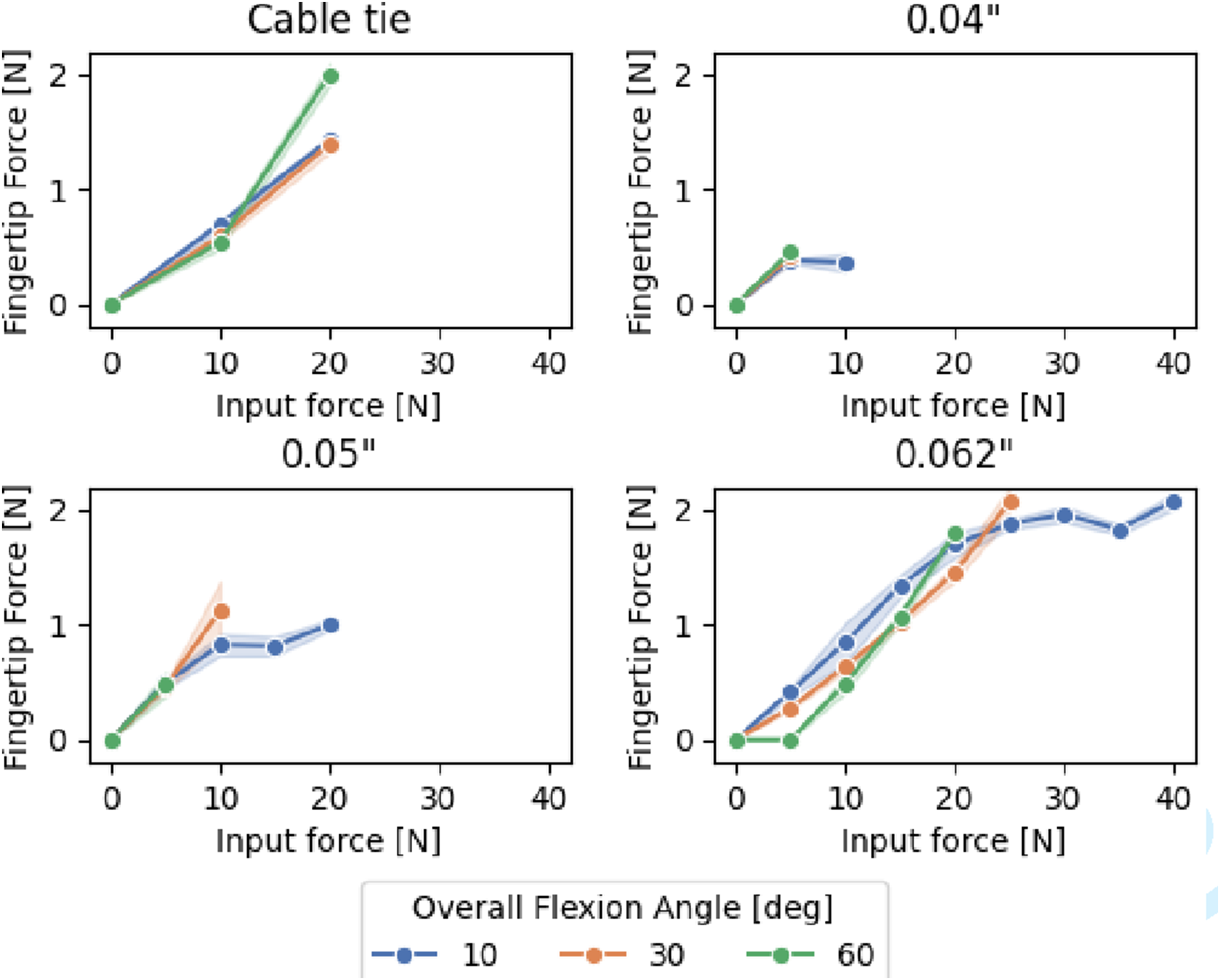
The main issue preventing a higher fingertip force was buckling, which made it impossible to reach the desired input force in some instances. At smaller overall flexion angles, this problem was less prominent, as the buckling was most likely to occur in the region between the distal and medial phalanges, which receives less input force than the region between the metacarpal and the proximal phalange. However, at larger overall flexion angles, this region was very prone to buckling. This can be seen by the fact that the green lines (60 o ) in Figures 11 and 12 always stop at a lower or equal input force than the curves for lower overall flexion angles.
The different finger geometries were tested to see which one could lead to the highest output force, as well as sustain the highest input force. The original finger design, using cable ties as spring blades, could withstand input forces up to 20 N at angles of 10 o and 30 o , but only 10 N at an angle of 60 o , with output forces of 1.43 ± 0.08 N, 1.5 ± 0.1 N and 0.4 ± 0.1 N, respectively. The configuration with a shorter proximal phalange didn’t seem to improve the performance of the underactuated finger, instead leading to it no longer being able to sustain an input of 20 N at 30 o . Similarly, the 5 mm supports reduced the performance at high angles and only improved the maximum input force possible at 10 o . The 10 mm supports maintained similar performance at 10 o and 30 o flexion angles, as well as improving the maximum input force at 60 o to 20 N, with an output fingertip force of 2.01 ± 0.09 N.
While the use of 10 mm supports seemed promising, the cable tie remained too prone to buckling and could neither withstand nor output large enough forces. Different thicknesses of wear-resistant nylon 66 strips, the same material used to make cable ties, were therefore tested. The thickness of the original cable ties was around 1.25 mm, and we tested 0.04” (1.016 mm), 0.05” (1.27 mm) and 0.062” (1.57 mm) thick nylon strips. The 0.04″ strips performed very poorly, not withstanding forces above 10 N at any angle, for a maximum of 0.46 ± 0.03 N. While the 0.05″ strips were slightly better, they still performed worse than the cable tie. This can be partially attributed to the fact that hand cutting the nylon strips could introduce thinner regions that were prone to buckling. The 0.062″ strips were much more successful, reaching at least 20 N of input force for all angles, for a maximum of 40 N at 10 o . The output forces were also higher, with 2.08 ± 0.07 N at 10 o , 2.1 ± 0.1 N at 30 o and 1.80 ± 0.04 N at 60 o .
Overall, the ratio of the input force required to obtain a particular output fingertip force, as shown in Figures 11 and 12, follows the expected behavior of the finger, according to the relative lengths of the lever arms. Figure 13 shows a free body diagram for the finger from which the expected input to output force ratio can be calculated according to equation (1). Free body diagram of the finger, with the relevant forces indicated. F
in
represent the input force applied to the blade, while F
out
represents the output force at the fingertip.
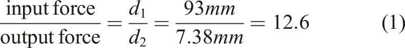
The results from Figures 11 and 12 yield a value of 16 ± 3 and 14 ± 4, respectively, which is close the expected result. The slightly higher than expected values can be explained by losses due to friction and the bending of the finger.
In addition to the fingertip force measurements, the output force for a medium wrap grip, where two or more sections of the finger contribute to the overall output force, was measured for the configurations using 0.05″ and 0.062″ strips. The same method as for the fingertip force measurement was used, with the addition of a 3D printed half-cylinder (diameter = 70 mm) fixed to the load cell (See Figure 10). The size of the cylinder was chosen to ressemble that of a standard water bottle, as such an object is a common example of one needing a medium wrap grip. Figure 14 shows the result of these measurements. The behavior of the fingers stayed similar for both values of thickness, but did not seem to be influenced by the angle at which the measurements were taken. Since the addition of the half-cylinder changes the overall flexion angle, it would also not be comparable with the fingertip force data. The overall flexion angle measurement has therfore been omitted for the medium wrap grip data. The results show that the overall output force acheived greatly increased. The 0.05″ strip reached a maximum output force of 3 ± 0.2 N, while the 0.062″ strip reached 4 ± 0.1 N, for an input force equal to that of the fingertip measurements. Output force for a medium wrap grip for the different thickness of nylon 66.
Size, weight and installation
The orthosis is placed on the back of the user’s hand, with a wrist splint worn on the forearm serving as the anchor point for the base of the mechanism (Figure 15). Its total weight is 136 g, including the wrist splint and the part of the orthosis that is on the user’s hand measures 3.5 cm × 9 cm, with a height of 3.5 cm. Front and back view of the orthosis when worn.
In addition to the hook and loop straps from the wrist splint, the orthosis is secured with four additional hook and loop straps: one around the medial phalange on the index finger, one around the thumb, one across the palm and one around the wrist. The orthosis can be put on independently by a neurologically intact subject, but, in the current iteration, not by a potential user without assistance.
Cost
Cost estimate of the orthosis.

Discussion
This article presented a low cost, fully mechanical hand orthosis for grasping assistance in activities of daily living. We demonstrated its ability to amplify the grasping force naturally given by the tenodesis grasp, without using any electrical components. We improved the design of the underactuated fingers to counteract the buckling introduced by the use of a more lightweight and low-cost material, nylon 66, instead of the more commonly used specialized stainless steel strips. In comparison to state-of-the-art fully mechanical orthoses, which are often designed with rehabilitation rather than all-day assistance in mind, our orthosis is less bulky. Its underactuated mechanism also requires far fewer elements, making assembly and customisation easier. Furthermore, while some orthoses require the use of the second hand for actuation, ours is entirely contained of the desired hand, making two handed grasps possible. The final design also took into account the opinions expressed by occupational therapists by leaving the palmar side of the hand almost compeltely free for optimal tactile feedback.
Design requirements
The orthosis could not fully reach the 5 N target value, instead reaching a maximum of 2 N at the fingertip. With a medium wrap grip, however, the finger benefits from more than one point of contact with the object being held. Two of those points of contact having shorter lever arms, this led to an increased output force of 4 N, which is much closer to the target value. Since most heavy everyday objects are larger and would warrant the use of a medium wrap grip, while those that could be grasped using a pinch grip are typically smaller and lighter and therefore require less force, it is likely that the flexion assistance provided would be sufficient to grasp most objects.
Similarly, with the use of the 0.062″ thick nylon strips, the underactuated finger could withstand a force of 40 N without buckling, at an overall flexion angle of 10 o . At larger angles, this maximum force was lower. However, a larger flexion angle is only necessary when grasping smaller objects, which are typically lighter and require less force. The input force possible with the orthosis could therefore still be used to carry many everyday objects.
Of the different methods used to try to prevent buckling, adding supports between the proximal phalange and the metacarple yielded the best results, both qualitatively (Figure 3) and quantitatively (Figure 11). While both 5 mm and 10 mm supports presented some improvements compared to the original design, either in terms of resistance to a higher input force or generation of higher output force at the fingertip, the 10 mm supports led to better results. They helped output equal-or-higher fingertip force to the other geometries at all overall flexion angles and were the only geometry that could withstand 20 N of input force at 60 o with the original tie wrap spring blades (Figure 11), making them the best option to reduce buclking.
The part of our orthosis placed on the back of the hand slightly exceeds the target value in the long direction, but can still fit comfortably even on small hands. It is also extremely lightweight, with the entire orthosis weighing well under the target weight for the back of the hand.
The use of hook-and-loop straps to secure the orthosis ensures that most of the palmar side of the hand remains free, which allows for maximum tactile feedback. However, these straps are difficult to attach by the user themselves, which prevents them from donning the orthosis independently. A neurologically intact user can don the orthosis by themselves in around 30 s.
Since our orthosis has a limited number of components, most of them 3D printed with PLA filament, and no electronics, it is inherently waterproof and can easily be cleaned by running it under water or using a washcloth.
Having most of its elements 3D printed also contributes to making our orthosis very low cost. At slightly above $15 of material costs for one orthosis, for a total of $332 with the additional costs factored in, the proposed orthosis is only about 27% of the cost of a comparable commercially available option.
Usability
While the 0.062″ thick nylon strips could withstand a high input force and provided the best fingertip force, the required input force was difficult to generate with the wrist even for neurologically intact users. This strip thickness could therefore be a great option for a motorized version of the orthosis, but the 0.05″ strips remain more suitable for a non-motorized one.
The two thumb support options ensure that most grasping tasks are achievable with our orthosis. However, since they have to be swapped out to use a different support, some of the flexibility is lost.
A single finger was actuated in the present version of the orthosis, but the addition of a second finger would only require minimal modificaion to the design of the orthosis: a second opening would need to be made in the slider and linear guides, while the metacarple of the underactuated finger would need to be widened to accomodate a second finger module. The same actuation strategy could be used, but it should be noted that since the input force provided by the wrist would be divided between the two fingers and not multiplied, the total added grip force for the entire hand would remain the same. The two fingers would therefore be actuated simultaniously, allowing for a tripod grasp, while keeping the current size of the orthosis, and with little added weight and cost. Adding a second two-finger module would allow all four fingers to be actuated simultaniously, but would double the size of the orthosis on the dorsal side of the hand, which will be an issue for many potential users.
Limits
The maximum fingertip force of 2 N is considerably below the target value of 5 N. However, a 4 N output force was reached with a medium wrap grip, which is much closer to the target value and better corresponds to a real-life grasping situation. Additionnaly, since the orthosis is not motorized, it may be more suitable for users who have a higher level of residual force, and therefore require less assistance. Our orthosis could then be sufficient to allow them to perform the grasping activities necessary for daily living, without the added cost and weight of a motorized orthosis.
This would however need to be confirmed with user testing, which we were not able to do with this study. Target user testing is part of the next step in the development of the orthosis.
In the present version of our orthosis, the thumb isn’t actuated, and can only accomodate two grasp types. While these grasp types account for a large proportion of those needed in ADL, an actuated thumb would allow for more freedom in terms of grasping types, and therefore greater versatility.
The tenodesis mechanism, while providing an intuitive and motor-free actuation to the orthosis, also limits its use to people with voluntarily movements in their wrist.
Conclusion
The proposed orthosis is one of the few fully mechanical flexible hand orthoses designed to assist grasping. The improved underactuated finger design allowed for good force transmission, while significantly reducing buckling in the upper spring. The fixed-length mechanism used to drive finger flexion from the rotary motion of the wrist was able to improve the performance of the tenodesis grasp, while remaining intuitive to use. The underactuated finger could output forces of up to 4 N, without any electronics. The use of 3D-printing allowed the orthosis to remain lightweight, with a total weight of 136 g, and exceptionally low cost, with a total price 27% of that of comparable commercial options.
Future works include actuating two fingers simultaneously to be able to perform tripod grasps. Other materials should also be tested to further improve the tradeoff between cost, weight and stiffness. Testing with potential users to improve the orthosis through an interative process is also an important future step. An EMG-controlled motorized version of the orthosis, capable of assisting finger extension as well as flexion, is in development as well. The motorized version of the orthosis will also remove the need for voluntary movement of the wrist, allowing people with severe wrist impairments to benefit from its use. Nevertheless, the orthosis presented in this article is a very promising option for people with moderately affected hand function and who do not desire a motorized orthosis.
Footnotes
Ethical considerations
Ethical approval was not required, as no human participants, human data or human tissue was used.
Funding
The authors disclosed receipt of the following financial support for the research, authorship, and/or publication of this article: This works was supported by the ”Centre Interdisciplinaire de Recherche en Réadaptation et Intégration Sociale” (Cirris); the ”Fonds de Recherche du Québec – Santé” (FRQS) [grant number. 251649] and ”Ingénierie de Technologies Interactives en Réadaptation” (INTER).
Declaration of conflicting interests
The authors declared no potential conflicts of interest with respect to the research, authorship, and/or publication of this article