
Abstract
Keywords
Introduction
Socket fit has been reported as the most important issue faced by people who use a lower-limb prosthesis.1,2 A key variable that affects socket fit is residual limb volume.3,4 Volume fluctuations change the distribution of pressure and shear stress on the residual limb and the limb’s position and motion within the socket.5–8 If volume fluctuations are not properly managed, concentrated stresses may be induced in residual limb tissues and cause injury, particularly in high activity prosthesis users such as Service members (SM). A period of no prosthesis use may be required until the damaged tissue heals, reducing activity, participation, and quality of life.
Traditional socket fit adjustment strategies, for example adding and removing socks or manually adjusting a volume-adjustable socket, are a trial-and-error process. Users make an adjustment, assess their socket comfort, and make additional adjustments until an acceptable fit has been achieved. This process is distracting. Prosthesis users continually sense if and how much socket volume change is needed and then interrupt their activity to effect the change. While it does not change socket volume, elevated vacuum adapts by adjusting its driving force to maintain a target vacuum between the liner and socket. This technology has shown some evidence of assisting with maintaining limb volume, enhancing volume stabilization and tissue health in some studies while in others it increased the risk of blister formation and was prone to pressure leaks.9–12 A better solution for management of limb volume may be an adjustable socket that automatically adjusts socket volume to maintain fit. 13 Auto-adjusting sockets implemented via on-board microprocessors receive data from sensors embedded in the socket wall to detect the amount of adjustment needed and move actuators to make the proper change.
Numerous volume adjustable socket designs have been described in the literature, but only a few closed-loop control systems advanced to human subject testing.13–18 The first closed-loop system was purely mechanical. In 2003 Greenwald et al. positioned liquid-filled bladders on the inside of the socket and a pumping bladder in the bottom of the socket. 18 When the residual limb displaced distally and put force on the pumping bladder, the system drove liquid into the side bladders, reducing socket volume. Gu et al. reported that a closed-loop control system designed for transhumeral prosthesis users was able to maintain a consistent contact pressure during lifting, however only a single able-bodied participant was tested, and no take-home testing was conducted. 14 A design specific to transfemoral prostheses 17 regulated the air pressure of inflatable bladders placed between a flexible inner liner and the socket wall of two participants to maintain constant pressure on the limb over time. While the investigators claimed to reduce motion between the liner and socket at the proximal brim (measured indirectly using inertial measurement units), air bladders are not an ideal system for automated control in high activity users because the relationship between air pressure and shape is inconsistent over time. The inability of air bladders to provide equal and consistent support has been a concern in manual systems as well. 19 An early prototype of the auto-adjusting socket used in the present study was tested in a group of 10 transtibial prosthesis users and implemented using a proportional integral control system to maintain a consistent sensed distance between the liner and socket during walking. The system achieved a mean controller radial position error of 0.003 mm, 15 demonstrating that the system was ready for clinical trial testing.7,20,21 Stable controller operation was demonstrated during 98% of walking bouts during a clinical trial (n = 6) in which socket volume was adjusted during alternating periods of walking and sitting. 16 Results suggested that matching the socket volume increase at the start of a new walking bout to the fluid volume increase in the residual limb experienced by the individual participant during sitting between bouts may improve comfort. During the only reported take-home testing of an auto-adjusting socket (n = 12), using a design similar to the present study, participants who walked more than 20 min/day demonstrated greater activity, less doff time, and fewer manual socket volume adjustments wearing the auto-adjusting socket compared with a locked-panel socket and a socket with a phone-app adjusted by the user. 13 Nine of the twelve participants reported that they would use a motor-driven adjustable socket if it were available as it would limit their socket fit issues. A next step, relevant to high activity users, is to test auto-adjusting sockets under physically demanding conditions that challenge participants’ physical endurance.
The purpose of this research was to test our auto-adjusting socket under activity conditions consistent with SM needs. We investigated the consistency in sensitivity of a participant socket fit metric to socket volume changes. In a simulated military environment while participants conducted military relevant tasks, we monitored socket volume adjustments and evaluated the socket’s capability to automatically adjust to maintain socket fit, enhance user performance, and improve self-reported outcomes compared with the socket in a static non-adjustable mode and a user-adjusted mode.
Methods
The study protocol (C.2020.007) was approved by the San Antonio Institutional Review Board in compliance with applicable Federal regulations governing the protection of human subjects. Participants were recruited via approved flyers distributed throughout the clinic and with the assistance of the clinical staff at the Center for the Intrepid (CFI). Written informed consent was obtained before study procedures were initiated.
Participants
Participants were included in this study if they were 18–55 years of age, had a transtibial amputation, were currently using a definitive prosthesis, were an Active-duty SM or Veteran, were authorized to receive care at the CFI and to comply with instructions associated with functional testing. Exclusion criteria included self-reported blindness, pregnancy, active infection, and the inability to ambulate continuously and unassisted for a minimum of 20 min. Pregnancy was an exclusion criterion because the motion platform in the virtual reality environment (described below) introduced a high risk. Participants’ weight could not exceed 127 kg when wearing a fitted vest, helmet, and rifle due to safety precautions in the virtual reality environment. Participants’ residual limbs could not be less than 9.0 cm in length from the mid-patellar tendon to the distal end of the limb. Participants could not have any activity restrictions that would preclude testing within a virtual reality environment, upper extremity injury that inhibited use of a rifle, or low back pain greater than minimal disability as assessed via the Modified Oswestry Low Back Pain Questionnaire. A score greater than 20% required exclusion from the study. 22 If the participant’s Post-traumatic stress disorder CheckList – Military version (PCL-M) score was over 60 then participation was deemed ineligible.
Investigational sockets and liners
The interior of participants’ prescribed, daily use sockets was scanned using an industrial coordinate measurement machine (FAROArm Platinum, FARO Technologies, Lake Mary, Florida; resolution <0.02 mm). A previously developed workflow 13 and software were implemented to modify the scan data into a manufacturing shape file (Geomagic, Design X, 3D Systems, Research Triangle Park, North Carolina; TracerCAD, WillowWood, Mt. Sterling, Ohio). If the participant did not regularly use pin suspension, the distal surface of the model was modified to add an umbrella shape and convert it to a socket with pin suspension, increasing the socket length. A positive foam model was produced (D2 carver, Provel, Cle Elum, Washington). Check sockets were fabricated using carbon fiber. The CFI research prosthetist fit the sockets to study participants and made minor modifications to the trimlines to ensure comfort and an acceptable range of motion within the standard of care. The research prosthetists marked the positions of three panels on the anterior medial, anterior lateral, and posterior midline surfaces to maximize panel size while avoiding pressure sensitive regions of the residual limb.
A second carbon-fiber socket (the investigational prosthesis) was fabricated with three inductive distance sensors embedded in the lamination at posterior lateral midlimb, posterior medial midlimb, and anterior distal locations23,24 (Figure 1(a)). The sensors measured the distance between the socket and a magnetically permeable target embedded in the investigational liner,24,25 the liners contracted for the project (Alpha Silicone Locking Liner, WillowWood). (a–c) Investigational prosthesis. (a) One of the sensor antennae used to monitor SFM is visible through the Nyglass on the inside of the socket. (b) Motor-driven adjustment mechanism that pushes the panels in or pulls them out. (c) Phone fastened to a participant’s upper arm.
The panels were cut out of the socket wall, and a frame holding a motor, panel, and adjustment mechanism was mounted to the socket over each opening (Figure 1(b)). A rod through the back of the panel allowed it to rotate about a horizontal axis parallel with the inside socket surface to avoid inducing stress concentrations at the top or bottom of the panel. The three panels simultaneously moved radially inward and outward equal distances via commands from the microcontroller. An app on a phone strapped to the upper arm of the participant (Figure 1(c)) was used to adjust panel positions during setup and to operate the controller in user-adjusted mode (step size: 0.25 mm, range of total radial adjustment 5.00 mm inward to 4.50 mm outward from flush). A sensor that recorded the height of the locking pin within the shuttle lock 26 was placed between the socket and pyramid adapter to identify pin notch changes during testing. Calibration procedures for the socket and pin sensors are previously described.13,26
The investigational socket was tested in three modes: static, user-adjusted, and auto. In the static mode, which simulated a traditional non-adjustable socket, no panel movement occurred. In the user-adjusted mode, the participants controlled the panel movement using the phone app. In the auto mode, the controller adjusted the panel positions during walking to maintain a consistent socket fit metric (SFM), which was derived from the average stance phase minima from the two posterior mid-limb liner-to-socket distance sensors (Figure 2). An infinite impulse response (IIR) filter and range limits were implemented to ensure stable controller operation.
13
The participant could override the system in auto mode and make socket volume adjustments using the phone app similar to user-adjusted mode. Example SFM over time illustrating operation of the socket in the three modes. In this figure, SFM is the average stance phase minima from the two posterior mid-limb sensors referenced to the median. The area under the curve is colored green when the SFM was greater than zero and red when it is less than zero. Large areas of red and green indicate relatively high SFM error, i.e., the distance between the liner and socket was not well-maintained. For the static mode, no adjustments were made. For the user-adjusted mode, the participant adjusted the socket as desired using the phone app. The SFM error was lower for the auto mode (3rd panel) than the static or user-adjusted modes (1st and 2nd panels) because the SFM signal was fed back into the controller to decide and implement panel adjustments.
Testing protocol
A prospective, randomized, repeated measures study design was executed. Testing was conducted in a simulated military environment using specialized military facilities.
Three visits were conducted to evaluate the participant and fit of the investigational prosthesis. During the first visit, informed consent was obtained, demographic information and health history information were collected, and limb dimensions were recorded. Questionnaires were administered to assess the participant’s Post-Concussion Symptom Scale (PCSS) to ensure that the virtual reality testing did not exacerbate any existing symptoms. At each visit, the participant was asked to provide a Socket Comfort Score (SCS), rating on a scale of 0 (worst) - 10 (best), 27 and a Numerical Pain Rating Scale (NPRS) score, rating on a scale of 0 (none) - 10 (worst), so that self-reported changes in comfort and pain of the prescribed socket could be tracked. The participant’s prescribed socket was scanned.
During the second visit, the check socket and investigational liner were fit by the research prosthetist using traditional clinical procedures including measurements and photographs of the residual limb, re-evaluation of liner size, donning/doffing instructions, static socket fit, and dynamic alignment. All participants demonstrated competency using the prosthesis and confirmed socket comfort. The investigational socket with the embedded sensors was fabricated, and the electronic pin sensor was added.
The third visit began with the participant using the investigational prosthesis and included a brief walk on a treadmill to verify dynamic alignment. Use of prosthetic socks was recorded. The relationship between socket volume and the SFM was assessed by conducting a participant calibration procedure on the treadmill termed a plant gain test. During this test, the socket panels were gradually adjusted from the self-reported preferred setting to the largest acceptable socket volume and then returned to the preferred setting. 13 Participants were given the opportunity to familiarize themselves with the investigational prosthesis by walking in the lab in auto and user-adjusted modes.
The remaining visits described below focused on using the investigational socket during military relevant tasks that could challenge socket fit. At the start of each visit, participants donned the investigational prosthesis and walked in the lab to acclimate to the socket. Socks were added, if necessary, though attempts were made to maintain consistent sock use. The relationship between panel position and the SFM was assessed (plant gain test), and the panels were set to the participant’s preferred socket volume. For auto mode the liner-to-socket distance sensor counts per mm panel radial displacement was programmed into the controller. The participant was fit with a heart rate monitor, smartphone in an armband, Kevlar vest, helmet, and mock M4 rifle. Data collection was initiated – SFM, anterior distal motion, pin depth, and motor position were recorded.
The participant completed two military readiness assessments with each socket mode (static, user-adjusted, and auto) for a total of six assessments. The socket condition and the order of the readiness assessments within each socket condition were randomized. One assessment included six Common Military Tasks (CMTs) adapted from the Marine Combat Fitness Test 28 and the Soldier’s Manual of Common Tasks. 29 The CMTs were high crawling and low crawling 8.0 m; dragging a 45.4 kg mannequin 7.6 m; engaging targets in standing, kneeling and prone positions; carrying two 0.30-caliber ammunition cans, filled with rocks to match the mass of a full can (∼9 kg each), a distance of approximately 15 m; and clearing a stairwell (walking up and down two flights of stairs, 12 steps per flight). Participants received standardized instructions and a demonstration prior to each assessment. Participants were allowed to rest as needed before the next instruction and assessment were begun, since some participants required long rests to continue. Participants’ time to complete each task was recorded using a stopwatch. Participants were instructed not to doff the socket between tasks unless they experienced socket discomfort. The Readiness Evaluation during simulated Dismounted Operations (REDOp) was the second assessment and took place in a virtual reality environment. 30 While walking on a six-degree-of-freedom treadmill platform in the Computer Assisted Rehabilitation Environment (CAREN), participants engaged silhouette targets in a series of ambushes. Each ambush included walking on different slopes at varying speeds and shooting marked targets. Participants were assessed on marksmanship and the number of completed ambushes.
SCS and NPRS were reported after each task or ambush. The REDOp assessment ended immediately if the participant requested stoppage, triggered the CAREN’s emergency stop, or there was a safety concern by the research team. The assessment ended at the conclusion of the current ambush if maximum heart rate (220 – participant age) (beats/min)31,32 was exceeded, NPRS increased by three or more points, or NPRS reached a value of six or higher. The PCSS was administered both pre- and post-assessment to verify no worsening of symptoms. The Quebec User Evaluation of Satisfaction with Assistive Technology (QUEST), Device Satisfaction portion was administered at the completion of each study condition. 33 The QUEST required participants to rate their satisfaction with the overall system on a five-point Likert scale (1 = not satisfied; 5 = very satisfied) for eight subscales and to select their three most important subscales. The eight subscales were: dimensions, weight, ease in adjusting, safe and secure, durability, easy to use, comfortable, and effective.
Data processing and analysis
Plant gain
A least-squared fit to the increasing socket-volume part of the plant gain test was calculated. The plant gain was the slope of this line.
Socket volume adjustment and performance metrics
The number of button presses adjusting the panels was determined from the smartphone application log, and the number of auto adjustments was determined from the motor encoder data logged to the board. Results were tabulated for the user-adjusted and auto mode for each participant.
Calculated metrics for REDOp and CMT protocols.
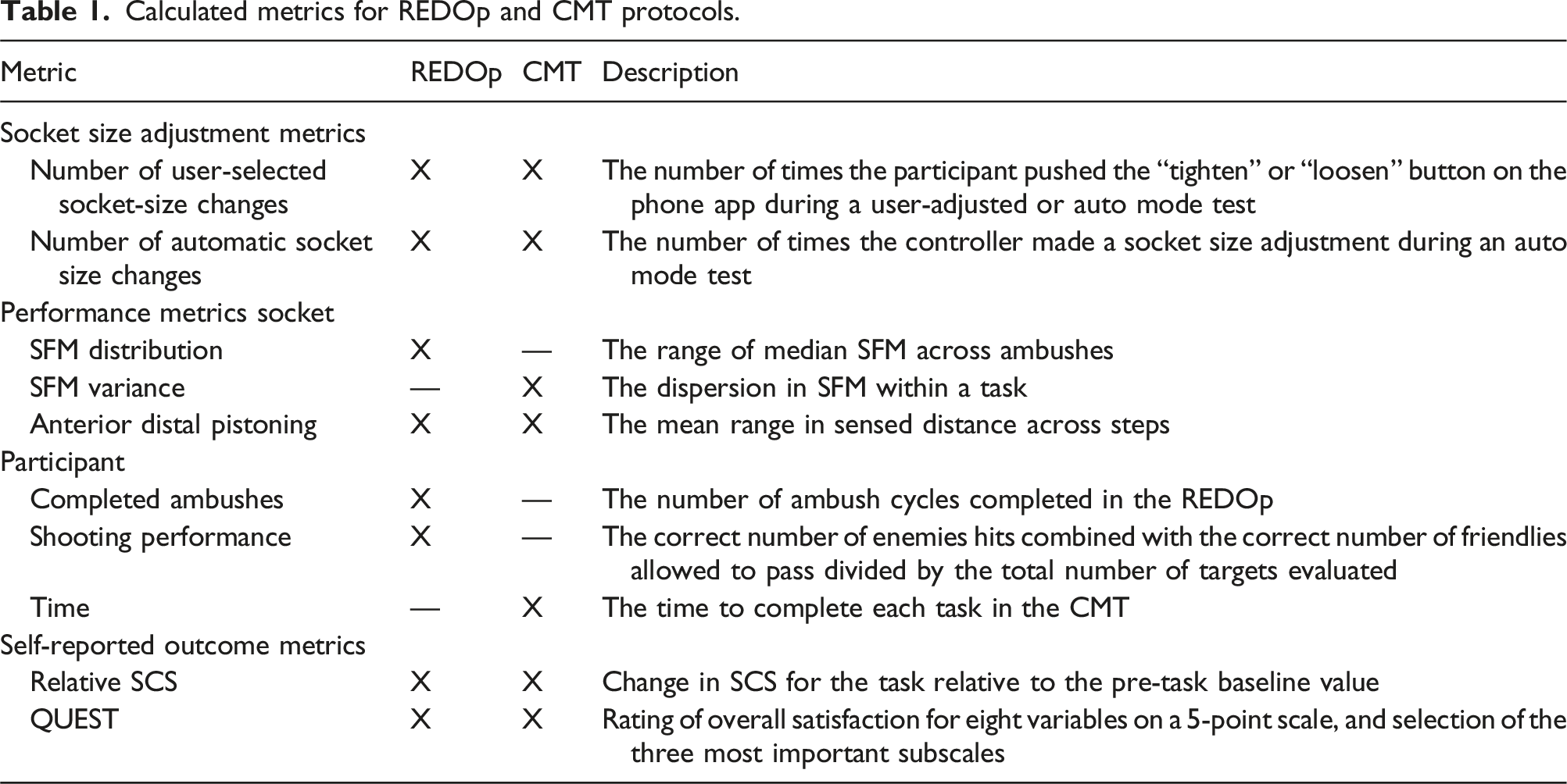
For the CMT, two metrics were calculated for each task: the SFM variance and the anterior distal pistoning. SFM variance (S
2
) was computed:
Ratio-based metrics were calculated for all socket performance variables to standardize the variability among participants. Each participant’s metric values were normalized to the maximum value observed over the three test conditions. Repeated measures ANOVA with Bonferroni adjusted pairwise comparison calculations were used to compare results for the three socket conditions. A test statistic of P < 0.05 was used. Mauchly’s Test was used to assess all data for sphericity.
Participant performance metrics
The number of completed ambushes in the REDOp was tabulated. Shooting performance was calculated by combining the correct number of enemies hit with the correct number of friendlies allowed to pass and divided by the total number of targets evaluated. The time to complete each CMT task was calculated.
Participant self-reported outcome metrics
Participants reported SCS prior to the REDOp assessment, after each ambush, and after each CMT task. The pre-assessment value was subtracted from each ambush or task value, respectively, to provide a relative change. For the REDOp each participant’s subtracted score was divided by the number of ambushes completed. Mean and standard error for the REDOp and each CMT task were calculated for each socket condition. The QUEST produced individual subscale scores and an overall satisfaction score (average of all subscale scores). For the QUEST data, a count of the number of times each subscale was ranked as one of the top three most important subscales was recorded.
Similar to the controller performance variables, a repeated measures ANOVA was used to test for statistical significance (P < 0.05). Mauchly’s Test was used to assess all data for sphericity. The socket conditions (static, user-adjusted, auto) were used as the levels of the within-participant factor for each outcome measure of interest.
Results
Participants
Participant demographic information.

Amp.: amputation; Circumf.: circumference; rpt.: report.
aCircumference taken 4 cm distal to the mid-patellar tendon.
bParticipant 6 has bilateral amputations. Right limb received the investigation prosthesis.
Prosthesis characteristics.

Data for both the traditional and investigational sockets are shown. Bold numbers indicate a sock thickness difference relative to the other test modes. Pt: participant.
aAll participants with suction and elevated vacuum wore sleeves.
bh = half sock; f = full sock.
Sensitivity to socket volume change
There was a wide range in the plant gain across the participant group, ranging from 869 to 4813 SFM counts/mm (Figure 3(a)). A low plant gain meant that there was little change in the SFM for a one-step (0.25-mm) radial position adjustment of the panels, and the opposite for high sensitivity. The participant plant gains over the three test modes varied by an average of 17.9% (±13.2) of their mean. Two participants, 12 and 15, demonstrated much different sensitivities for the auto mode test day than the other two test mode days. Participant 12’s was approximately 2x that of the other 2 days (4045 vs 2022-2046), and participant 15’s was about 0.6x that of the other two test days (869 vs 1371–1462). There was a moderate correlation between the number of ambushes executed in the REDOp and participants’ mean plant gain (R = 0.466). (a, b) REDOp test results. (a) Plant gain results for each mode. (b) Number of ambushes completed for each mode.
The data below are presented in order from the highest to the lowest number of ambushes for the auto mode in the REDOp to better highlight variables that changed in relationship to activity time. Participants’ number of ambushes for each mode are summarized in Figure 3(b).
Socket volume adjustments
Panel position data demonstrated how participants chose to use the socket (user-adjusted mode) and how the controller made adjustments (auto mode). The auto mode showed a wider range of adjustment for all participants (P = 0.001) (Figure 4). In the REDOp user-adjusted mode, four participants (3, 12, 13, 15) chose not to make adjustments thus their user-adjusted was identical to their static protocol. However, panel positions were at least 1.0-mm different. Most of the participants were not able to achieve an acceptable socket fit at the flush position (panel position = 0) for static mode despite adjusting sock thickness. Those participants (9 of 11) adjusted the panels to a comfortable setting at the start of the static mode. Thus, the static mode was not the participant’s traditional socket shape. Panel position ranges for all test sessions in the REDOp.
In the user-adjusted mode in the REDOp, all participants made 3.0 or fewer adjustments/ambush (Figure 5(a)). In auto-mode the controller made more adjustments, between 7 and 116 (median 32) adjustments/ambush (P = 0.003) (Figure 5(b)). Four participants (7, 8, 10, 12) occasionally overrode the controller in auto-mode. (a, b) Socket volume adjustments in the REDOp. (a) User-adjusted mode. (b) Auto mode. Both automated adjustments (green bars) and user-initiated overrides (light orange bars) are included for the auto mode.
In the CMT user-adjusted mode, no participant made any adjustments during two of the three walking activities: mannequin drag, ammo carry. Two participants (12, 15) made two adjustments each during the third walking activity, the stair clearance (participant 12 = 2 loosens; participant 15 = 2 tightens). In the three non-walking activities, i.e., the high crawl, low crawl, and shooting position, four participants made a total of 8 adjustments (7 tightens and 1 loosen), 7 of which were before or after the activity, not during.
In auto mode in the CMT, the system made adjustments during 7 of the 11 mannequin drags, 10 of the 11 ammo carry tasks, and all 11 of the stair clearance tasks, significantly greater adjustments than the user-adjusted mode (P = 0.026, 0.003, 0.002, respectively). None of the participants made an adjustment overriding the controller in these walking tasks. In the three non-walking tasks, participants overrode the controller 5 times, all loosens, but 4 of those were before or after, not during the activity.
Socket performance
In the REDOp, the distribution of the median SFM error for the group was significantly less for the auto mode than the user-adjusted (P = 0.023) and the static mode (P = 0.010). The user-adjusted and static mode were not significantly different (P = 1.000) (Figure 6(a)). The anterior distal pistoning was lowest for the auto mode but was not significantly different from the other two modes (Figure 6(b)). The 4 participants who underwent 3 or more ambushes in the REDOp were the only participants who showed lower anterior distal pistoning for the auto mode compared with the other two modes. (a, b) SFM distribution and anterior distal pistoning for the three modes in the REDOp. Y-axes are the ratio-based metrics as described in the text. Means and standard errors are shown. *P = 0.010, **P = 0.023.
In the CMT, though mean SFM variance (Figure 7(a)), and anterior distal pistoning (Figure 7(b)) were lowest for the auto mode for all three walking tasks, the differences were not statistically significant. (a, b) SFM variance and anterior distal pistoning for the ambulatory tasks in the CMT. Y-axes are the ratio-based metrics as described in the text. (a) SFM variance. (b) Anterior distal pistoning. Ratio-based metrics are presented. Means and standard errors are shown.
Participant performance
There was no significant difference between modes in the number of completed ambushes or shooting performance. Participants’ shooting performance ranged from 80% to 100% (median 98%), though performance was not recorded in two of the test sessions (one each for participants 1 and 3) because the CAREN instrumentation did not function properly.
Seven of the 11 participants stood or sat during the time between tasks. Three participants doffed the investigational socket at least once during one mode (2, 10, 13) and one participant (12) doffed the socket multiple times during all three modes. There were 8 doffs between tasks: 3 high/low crawl; 1 low crawl/mannequin; 1 mannequin/shoot; 2 shoot/ammo; 1 ammo/stair. Participants spent a mean of 29.1 s (median 25.6, range 5.3–102.3) conducting each task in the CMT and a mean of 350 s (median 160.6, range 62.5–2982.9) resting between tasks. There were no significant differences between modes.
Self-reported outcomes
A decrease in SCS from baseline was shown in all three modes during the REDOp assessment (Figure 8) with static mode showing the largest decrease, and user-adjusted mode the smallest. There were no significant differences between any modes. SCS change data for one participant (13) were not included in analysis since he completed only one ambush. SCS subtracted from the baseline for the three modes in the REDOp and divided by the number of completed ambushes. Means and standard errors are shown.
SCS reductions from baseline during the CMT were higher for static than user-adjusted or auto modes for all six tasks except the stair clearance (user-adjusted higher than static) but the differences were not statistically significant (Figure 9(a) and (b)). The mean SCS change was lower for the auto mode than the static or user-adjusted mode during the stair clearance, the task with the highest number of auto mode panel adjustments, but the differences were not statistically significant. (a, b) SCS subtracted from the baseline for the three modes in the CMT. (a) Walking tasks. (b) Non-walking tasks. Means and standard errors are shown.
QUEST data was collected on 9 of the 11 participants. The QUEST was added after receiving feedback from the first two participants. There were no significant differences between factors or between modes in the QUEST scores (Figure 10). Comfort and weight were most frequently selected as the most important variables to participants with dimensions being the least selected (Table 4). QUEST 5-point scale results. Participant satisfaction for the QUEST variables for each socket condition. A high value indicates strong satisfaction. Means and standard errors are shown. QUEST results. For each subdomain, percentage of participants who chose that subdomain as one of their three most important variables.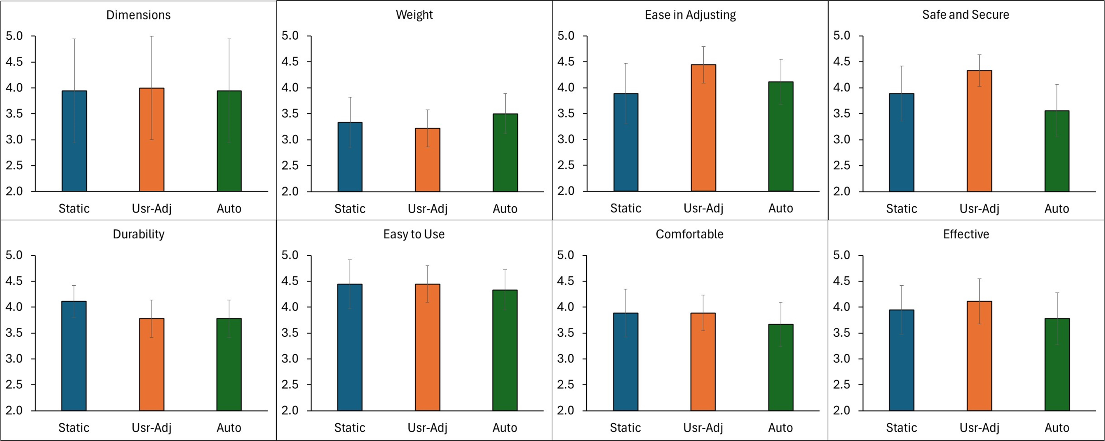

Discussion
The purpose of this research was to determine if an automatic socket that adjusted socket volume during walking better maintained socket fit, enhanced user performance and improved self-reported outcomes during military relevant tasks compared with a user-adjusted and a static mode. Results from this study demonstrated that the auto mode significantly lowered the SFM distribution, adjusted socket size more often, and put the socket through a greater adjustment range. There were no significant differences in socket comfort.
Similar to Greenwald’s product described in 2003, 18 we implemented a closed-loop system with socket-volume adjusting elements at the anterior tibial flares and posterior midlimb. Unlike Greenwald, we implemented an electro-mechanical system instead of a purely mechanical one, and we controlled the displacement of rigid socket panels instead of controlling pressure within fluid-filled bladders. Our system achieved tighter control and better consistency over socket adjustment, which may have improved performance. The locations of the adjusting element used by both investigators are now industry standard, implemented in commercial adjustable-panel products. Other closed-loop controlled fluid- or air-filled systems have not advanced to clinical trial testing.
The user-adjusted changes participants made did not stabilize their SFM during the REDOp, which involved steady state walking on undulating terrain, as well as the auto mode did, suggesting improved performance in the auto mode. The method the controller implemented, frequent and small changes, was more effective than the occasional adjustments participants made. Using the prosthesis while in user-adjusted mode was slower and more distracting because participants had to both sense their socket fit and take appropriate action to alleviate their discomfort. In auto mode, this challenge was alleviated. 34 Prosthesis users may have different preferred comfort levels which would correlate to different decisions on socket adjustments.
SFM distribution was the only socket performance metric that showed statistically significant differences between modes. The remaining socket performance metrics, SFM variance in the CMT and anterior distal pistoning in both tasks, were lower for the auto mode than the static or user-adjusted modes but were not statistically significant. This finding may reflect the limited active use time during the REDOp test (in 17 of the 33 REDOp test sessions, two or less ambushes (<9 min) were executed), the short duration of the tasks in the CMT (mean 29.1 s), and relatively long resting time between tasks (mean 350 s). Some of the participants in the CMT test found it necessary to doff their prosthesis between tasks which likely exacerbated their fluid volume change between tasks. Doffing after activity has been shown to increase limb fluid volume and cause a greater change in SFM upon subsequent donning.16,35,36
The result in the REDOp that the 4 most active participants were the only ones who demonstrated lower anterior distal pistoning for auto mode is consistent with our recent take-home study that the controller, which is active only during ambulation, must be active above a threshold time for statistically meaningful differences in performance to be detected, 13 suggesting that the auto mode is more effective for active users.
Of the ambulatory tasks in the CMT, the stair clearance during auto mode showed less decrease in SCS compared with the static or user-adjusted mode (Figure 9(a)). This result may reflect frequent and small adjustments were more favorable than no or infrequent adjustments.
For the other tasks, it is likely that the SCS was not sensitive enough to detect changes, our sample size was too small, and the short nature of the protocols did not allow for the users to fully realize a change in SCS. There is a need for more sensitive self-report outcome assessment metrics for the assessment of prosthesis componentry changes in short-term investigations.
Participants considered comfort and the weight of the investigational prosthesis the most important variables affecting their perceptions of their prosthesis, but there were no significant differences between modes for any of the QUEST metrics (Figure 10). All but two participants utilized a suspension system other than pin in their prescribed socket (Table 3) which could have lead to greater discomfort and impacted their perception data.
Future work
Based on this study and prior investigations,13,16 as both user-adjusted and auto-adjusted sockets become more available to prosthesis users, we expect there to emerge three groups of users: (1) active adjusters who choose to continually adjust their socket volume according to how the socket feels or in preparation for a change in activity level; (2) minimal distraction adjusters who prefer to allow an automated system make socket volume adjustments for them; and (3) rest-only adjusters who make socket volume changes themselves only while resting, in part as an effort to stabilize their residual limb fluid volume and possibly in anticipation of their next activity. An important research challenge is that currently it is unknown how many prosthesis users would be in each group, if patient and socket characteristics are related to outcomes for each group, and if fitting and training procedures can be optimized to enhance outcomes. An important observation from this study and others to date 34 is that participant-initiated adjustments may be reactive, executed well after a change in socket fit has occurred. Some degree of soft tissue injury may already have happened by the time the user makes an adjustment, and this change in tissue health should be considered to optimize clinical socket volume management.
User-adjusting sockets may be preferable to the traditional socket fit adjustment strategy of changing socks because the socket does not need to be doffed. However, because adjustments can be made quickly, users may inadvertently make inappropriate decisions on socket fit changes that increase the likelihood of skin breakdown. This potentially harmful application of user-adjusted sockets may be exacerbated in patients who have limited sensation or who have not received proper training on how to make appropriate volume adjustments. These outcomes might be improved through auto-adjustment technology. The outcomes might also be improved through additional research efforts developing different training strategies and comparing how they affect performance and limb health in the long-term.
Limitations
The short-term use of the investigational sockets and the modification to pin suspension for 9 of the 11 participants may have influenced study results. Participants did not wear either the carbon fiber test socket or the investigational socket for an extended time to re-evaluate the final fitting adjustments. This variation from prior adjustable socket studies was necessary due to time constraints on the participants. Prior work had the participants consistently demonstrate an acceptable fit at the neutral panel position (radial distance = 0) during extended testing for at least a few hours before any adjustable socket testing was started.13,15,16,34 In prior studies, the control condition (static mode) was the neutral panel position. In the present study, the neutral panel position was unacceptable to most participants since they could not achieve an acceptable socket fit. This difference in protocol design, as well as differences in sock thickness/panel position across modes (Table 3), may have contributed to the reduced differences in the performance metrics between modes, especially for the participants where the protocols were shorter (two or less ambushes in the REDOp). The result that the decrease in SCS relative to baseline was greater for static mode than user-adjusted or auto modes highlights the possibility that the socket volume at the start of activity may have a strong impact on subsequent socket fit over at least the next 10 min, consistent with results from our prior study. 16 In the CMT some participants prepared for an activity by making adjustments between tasks, highlighting the anticipation of a change in comfort that could lead to socket fit changes that may or may not have benefited the participant during the task. Setting socket volume properly at the outset of activity may be highly relevant.
The inconsistency in plant gain for the auto mode test day compared with the other two mode test days for the two participants who demonstrated the greatest percentage difference, 12 and 15, was reflected in their SFM data. Participant 12 overrode the controller in auto mode, possibly to correct for the excessive plant gain. Participant 15 executed the second fewest number of ambushes in the REDOp of any participant. In the future, collecting an average plant gain at several times during a session or over several test days or test conditions may be more appropriate for auto-adjusting sockets.
Conclusion
These results highlighted the errors in socket fit that happen in user-controlled sockets and how an automatically adjusting socket can minimize errors in socket fit during ambulatory activity while not impeding performance. In near-term prosthetics, research study focus will likely be on the development of best practices for user-controlled sockets since they will dominate the adjustable-socket market. Consensus statements from prosthetists experienced in successful design and fitting may be a powerful force for advancement. Technologies that track participant adjustments (e.g., an instrumented ratcheting dial 37 ) may facilitate education and fitting. As the body of knowledge matures, auto-adjusting socket technologies that foster best practices would be expected to emerge.
Supplemental Material
Supplemental Material - Testing an adjustable prosthetic socket in a simulated military environment
Supplemental Material for Testing an adjustable prosthetic socket in a simulated military environment by J. C. Mertens, C. A. Price, M. E. Baumann, N. S. DeGrasse, K. J. Allyn, A. Salazar, W. L. Childers and J. E. Sanders in Journal of Rehabilitation and Assistive Technologies Engineering
Footnotes
Author contributions
JM and ND fabricated and assembled the sockets, collected bench test and calibration data, prepared the microcontrollers, collaborated remotely during data collection, completed the control system analysis, and did the final data processing and presentation. CP provided socket fabrication expertise. MB and AS uploaded the plant gains for the controller. CP, MB, and AS helped with protocol planning, calibration, and data collection, performed initial data processing, and conducted the self-report data analysis. KA assisted with panel sizes and location decisions and clinical data review. All co-authors advised on study design and data interpretation, reviewed and edited the manuscript. LC and JS provided project management and advised on data analysis.
Funding
The authors disclosed receipt of the following financial support for the research, authorship, and/or publication of this article: This material is based upon work supported by the US Army Medical Research Acquisition Activity (USAMRAA) under Contract No. W81XWH1920049. Any opinions, findings and conclusions or recommendations expressed in this material are those of the authors and do not necessarily reflect the views of the US Army Medical Research Acquisition Activity (USAMRAA). The views expressed in this manuscript reflect the results of research conducted by the authors and do not necessarily reflect the official policy or position of the Henry M. Jackson Foundation for the Advancement of Military Medicine, Inc., the Defense Health Agency, Department of Defense, nor the U.S. Government.
Declaration of conflicting interests
The authors declared no potential conflicts of interest with respect to the research, authorship, and/or publication of this article.
Guarantor
JE Sanders PhD.
Supplemental Material
Supplemental material for this article is available online.
References
Supplementary Material
Please find the following supplemental material available below.
For Open Access articles published under a Creative Commons License, all supplemental material carries the same license as the article it is associated with.
For non-Open Access articles published, all supplemental material carries a non-exclusive license, and permission requests for re-use of supplemental material or any part of supplemental material shall be sent directly to the copyright owner as specified in the copyright notice associated with the article.