
Abstract
Introduction
Maintaining balance during perturbations is essential for the effectiveness of exoskeletal assistive devices in individuals with spinal cord injuries (SCI). We tested new ankle actuators in a muscles-first, motor-assisted hybrid neuroprosthesis (MAHNP) to evaluate their ability to maintain upright posture under various perturbations.
Methods
Participants with SCI (n = 2) performed standing balance tasks while wearing the MAHNP with and without ankle control, combined with electrical stimulation for one participant. A proportional, integral, derivative (PID) controller maintained 5° dorsiflexion based on input from an angle encoder. MAHNP’s balance control mechanisms were evaluated by the center of pressure (CoP) excursion during unexpected perturbations for both participants, while hands-free standing, range-of-motion tasks, and functional reach tests were completed by one participant.
Results
Active control provided important functional benefits by improving forward reach by 4.3 cm compared to no control, and extending hands-free standing time by 28.3% compared to no control. Additionally, variance in mediolateral CoP excursion was reduced from approximately 57% with no control to around 50% with control.
Conclusion
These findings suggest that while PID-controlled ankle actuators perform well in quiet standing, further optimization may be required for tasks involving more dynamic movements and voluntary postural tasks.
Introduction
Paralysis due to spinal cord injury (SCI) can limit an individual’s mobility and negatively impact their quality of life. 1 The sedentary lifestyle often adopted after SCI can cause secondary health complications, such as muscle atrophy,2,3 bone density loss,3–5 decreased cardiovascular function,4–6 and increased fat mass. 7 With approximately 302,000 individuals living with an SCI in the United States in 2023, and a projected increase of 18,000 new SCI cases per year,8,9 there is a clear need to develop systems that improve mobility following SCI.
Anthropometric powered exoskeletons are assistive devices worn in parallel to the user’s lower limbs to enhance mobility after paralysis from SCI via electric motors at the joints.10,11 Different exoskeleton models may be better suited for individuals with varying levels of SCI since ASIA-AIS classifications influence the degree of motor function and sensory preservation. 12 Herein, we focus on exoskeletons designed for participants with AIS complete classifications who have sufficient trunk and upper extremity control to maintain upright posture using crutches or a walker. These type of exoskeletons have been recently employed in rehabilitative settings or home use with a spotter for improving muscle tone and strength for individuals with incomplete SCI,13–16 and several models have been marketed in the United States for both clinical and at home-use.17,18 Clinical studies report a reduction in pain and spasticity,19–22 enhanced bladder and bowel function,20,21 and improvements to bone density 23 and muscle tone. 24 Unlike commercial, motor-driven exoskeletons, hybrid exoskeletons25–28 including the Motor-Assisted Hybrid Neuroprosthesis (MAHNP) designed by our team, 29 incorporate electrical stimulation (ES) with the goal of further counteracting negative secondary health complications of lower-limb paralysis by applying small electrical currents via surface or implanted electrodes2,3 to activate paralyzed muscles in conjunction with the exoskeleton’s prescribed movements.
Regardless of the control and design approach, active balance control is not a feature of many exoskeleton models and is a recently emerging topic within the literature. While numerous studies have analyzed the human response and recovery from destabilizing perturbations,30–33 or methods to maintain balance in bipedal walking robots,34–38 few explore balance with a human-in-the-loop, such as an exoskeleton. 39 The robotics literature provides numerous examples of bipedal balance control, 40 including dynamic modeling, 11 zero moment point,41–43 centroidal movement pivot, 44 foot rotation indicator,45,46 and capture point 47 approaches. However, applying those concepts to exoskeletal robotic systems that involve humans in the loop creates unique challenges, such as obtaining accurate parameters to use with these systems. 48 Additionally, calibration procedures for such analytical approaches may be unduly lengthy or difficult and therefore burdensome for participants with SCI.49–51
Humans maintain balance through multi-segmental control of the hips, knees and ankles.52,53 Balance strategies depend on several factors, particularly perturbation magnitude, with smaller disturbances typically engaging an ankle strategy, while larger ones incite a hip strategy, or a combination of both.53,54 However, studies of exoskeletons with actuated ankles have received relatively little attention, and the influence of rigid, exoskeletal bracing on human control strategy, such as modulating between hip and ankle control, is still an active area of exploration. The effect of actuated single-joint ankle exoskeletons on metabolic cost of transport has been investigated,55,56 as well as a multi-joint exoskeleton with powered ankles for enhancing walking performance in able-bodied studies. 48 However, exoskeletons marketed for SCI are typically only actuated at the hip and knee joints while the ankles are secured via a rigid ankle-foot orthosis. Some hands-free exoskeletons are designed with active balance control, such as ATALANTE’s Wandercraft57–59 or REX by Rex Bionics.60,61 These models include motors at the ankle joints to maintain upright stability and balance via the center of mass (CoM) and zero moment point methods, similar to those prescribed in Honda’s ASIMO Robot,62–65 where the CoM typically remains within stable regions under slow walking or standing conditions. At a single-joint level, an ankle-foot orthosis was also investigated in reducing ankle torque between controller conditions (zero intervention, body sway control, and virtual ankle stiffness) during perturbed standing of healthy individuals. 66
Despite progress with electrical stimulation for balance control,67–73 its integration with hybrid exoskeletons has yet to be fully explored. This paper presents a proof-of-concept feasibility study detailing the design and evaluation of actuated ankle joints for use in an exoskeleton (MAHNP) that combines both muscles-generated and motor-driven power and their effectiveness in maintaining the upright posture of participants with SCI in the presence of internal and external perturbations.
Methods
MAHNP ankle actuator design and proportional-integral-derivative control
The MAHNP (Figure 1(a)) features six actuators—two each at the hips, knees, and ankles—with passive resistances of 8.4 Nm for the hip/knee actuators and 6.5 Nm for the ankle actuator. These actuators were designed with the goal of reducing the passive resistances seen at the joints of our prior semi-active exoskeleton.
74
These relatively low resistances were designed to ensure that contractions of paralyzed muscles, generated by ES, are the primary drivers of movement.29,75,76 The power units were linked by adjustable pylons made from stainless steel tube clamps and aluminum tubing, which allowed for limb length adjustments and up to 20° of passive fitment adjustment in the sagittal and coronal planes via pyramid adapters (P17NSS-4, Bulldog Tools, Lewisburg OH). (a) Motor-assisted hybrid neuroprosthesis (MAHNP) with hip, knee, and ankle assistance (b) 3D rendering of the ankle joint, and (c) the physical ankle actuator, showing motor and roller chain sprockets.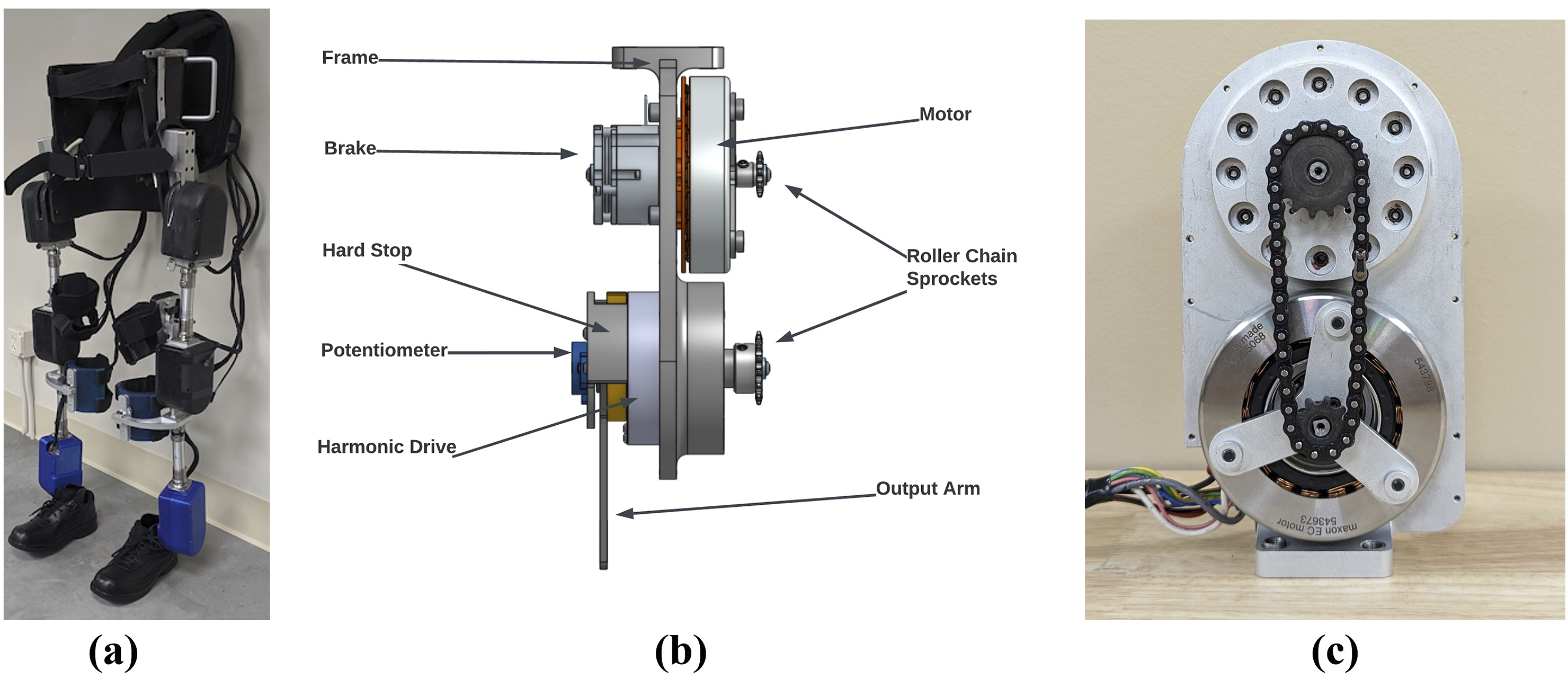
The ankle actuator design (Figures 1(b) and (c)) adapted the hip and knee actuator designs from Reyes et al. 75 and Nandor et al.29,76 to incorporate modifications specifically for the ankle joint. It incorporates a more powerful frameless brushless DC motor (543,673, Maxon Precision Motor). The new frameless motor shared a shaft with the electromagnetic solenoid brake (SB-17B12-E04S) for a more compact design. A roller chain connected the motor and a harmonic drive transmission (CCD-20-50-C-I, China Harmonic Drive), resulting in a total transmission ratio of 83.3:1. The actuator provided a continuous torque of 26.75 Nm, peak torque of 37 Nm, and a maximum angular velocity of 360°/s. A precision potentiometer measured joint angles, while mechanical hard-stops limited ankle dorsiflexion to 20° and plantarflexion to 25°. An aluminum central frame and mid-plate facilitated repairs and reduced weight. The actuators were powered by three 28.8 V lithium-ion batteries, with ES administered through either surface or implanted electrodes.
Ankle motor currents were controlled in real-time by a proportional-integral-derivative (PID) controller in MATLAB Simulink, maintaining a 5° dorsiflexion target due to user tendencies to lean slightly forward during erect stance. However, no hard stop at 5° was imposed to allow for a greater range of motion when completing tasks, although this range typically remained within 2° of the set-point. The Simulink model communicated with a Speedgoat RealTime Target Machine (Köniz, Switzerland) via CAN bus to a propulsion module with two microcontrollers (Teensy 3.6) running at 100 Hz. With less than 100 lines of C-code and total communication time less than 10 milliseconds per step, the PID controller adjusts current in real-time, capped at ±10 Amps, based on feedback from position error from the potentiometer. Potentiometers attached to the actuator output via a D-shaft measured the actual ankle angles. The error between the measured and target position signals was the feedback to the PID controller.
The PID controller was tuned first on the bench by manually manipulating the output arm of the actuator from its target position and qualitatively observing its ability to sufficiently return to the target and maintain that position. A neurotypical volunteer wore the ankle joint and shifted their weight back and forth and the controller parameters were adjusted until a typical response with only a single overshoot was obtained. Final values of proportional, integral, and derivative terms were constant amongst all participants (p = 0.25, I = 0.0012, D = 0.02) and perturbation types except for minor adjustments due to changes in user body masses.
Study participants and experimental protocol
We collected standing data from two individuals with SCI (1 female, 1 male) with approval from the Institutional Review Board at Louis Stokes Cleveland VA Medical Center (#16027-H18) and written informed consent. A physical therapist was present for safety during data collection. Both participants used the same ankle actuators, although required different interventions for standing and locking the hips and knees, and are therefore presented here as two separate case studies: • Participant 1 (AIS B C7): Due to device misalignment and fitment issues, Participant 1 stood with a surgically implanted stimulation system68,77–81 while wearing only MAHNP’s ankle joints. This implanted neural prosthesis consists of an 8-channel
82
and 16-channel
83
pulse generator capable of supplying 24 total channels of stimulation. For Participant 1, targeted muscles included trunk extension (bilateral quadratus lumborum and erector spinae), hip extension (bilateral gluteus maximus, hamstring, gluteus medius, posterior portion of adductor magnus), and for knee extension (bilateral quadriceps). The amplitudes (0–20 mA) and pulsewidths (0–255 microseconds) were configured to maximize performance and eliminate spillover to undesired functions. Stimulus frequency was 20 Hz to all implanted electrodes. This process is detailed more thoroughly in Triolo et al.,
84
where stimulation ramps are created based on the minimum amplitude that first elicits a visible muscle response and the maximum amplitude which causes adverse movements or sensations. Under these ES conditions, the hips and knees can be considered locked. • Participant 2 (AIS B T4) was not administered ES. They used the full MAHNP exoskeleton with the hip and knee joints locked.
Regardless of the intervention, data collection amongst the two participants were consistent. They stood on force platforms (AMTI, Natick, MA, USA) within the work volume of a 16-camera motion-capture system (Vicon, Oxford Metrics, UK) and held the handles of a custom aluminum standing-frame. We placed 38 retroflective markers on each participant and on the MAHNP joints. Force plate data was recorded at 1000 Hz, and motion capture data at 100 Hz using Vicon Nexus software. We randomized two controller conditions: 1) No active control with ankle joints unlocked (hereafter, OFF), and 2) actively controlled ankle joints via PID (hereafter, ON). Examples of each of the perturbation subtypes are shown in Figure 2 and detailed as follows. Participants during (a) unexpected perturbations from being pulled by a rope around the waist attached to a linear actuator, and (b) functional test of forward reaching.
Unexpected external perturbations
Participant 1 and 2 completed these tasks. A linear actuator (Copley Motion Control, Canton, MA) was positioned at waist-height immediately to the front of the participant. We applied controlled, repeatable perturbations to the pelvic region in the anterior-posterior direction via a rope tied between the actuator and a gait belt secured to the waist. The actuator was controlled by issuing a force command (expressed as a % of the participants’ bodyweight), that was then converted to actuator control current using an empirically derived relationship between mass and actuator current (Amps/Newton) before being sent to the actuator through a CAN connection and the Real-time toolbox in MATLABTM SimulinkTM,® (Mathworks, Natick, MA, USA).
Prior to data collection, we first prescribed very small perturbations and steadily increased their magnitude until the participant was perturbed enough without requiring intervention or re-stabilization by the PT, or the participant reported discomfort or concern. We then prescribed 75% of this maximally tolerated magnitude as the prescribed perturbation, which was 10% BW for Participant 1, and 15% BW for Participant 2. Trials consisted of at least 10 perturbations and participants completed at least two trials each of the passive and controlled ankle joint conditions. We did not randomize force intensity throughout the trials, although perturbation times were randomized between 3 and 5 s apart.
Participants were instructed to respond to the perturbations as they deemed fit. We did not impose any restrictions or offer suggestions regarding the use of hands or other balancing strategies. This approach was primarily for safety since the participants had varying AIS levels. They were free to adopt the corrective strategies they felt were most appropriate for their specific situation, and we captured their respective responses accordingly without introducing bias.
Functional tasks
Participant 2 completed three additional destabilizing movement tasks with the two controller conditions, repeated at least 2 times per condition. Each movement began standing with both hands on the standing frame and then proceeded as follows: • Functional Reach Test: With the preferred hand, reach forward in the anterior direction as far as possible without losing balance or requiring assistance by the PT to stabilize. The participant was allowed to apply the other hand on the standing frame as necessary. • Hands-Free Standing: Remove both hands from the standing frame and stand for as long as possible without returning a hand to the standing frame handles to re-stabilize. In the event of re-stabilization, the participant was allowed to remove their hand again to return to hands-free standing. We recorded 2 trials per controller condition, where the total time of hands-free standing during each 30 s trial was recorded. • Range of Motion: With the preferred arm, reach laterally as far as possible, then raise the arm above the head, and then perform a large circular motion in the sagittal plane through the full range of motion of shoulder flexion/extension. The pattern was repeated two times per trial. We recorded five trials per condition. The participant was instructed to minimally stabilize themselves via the standing frame handle.
Data organization and statistical analysis
Raw, deindentified data has been made publically available. 85 Data was processed in MATLAB with each participant serving as their own control. First, we grouped the data into respective perturbation subtypes, such as the external perturbations, and functional tests, separated into reach test, hands-free standing, or range of motion categories. Next, the times of each perturbation, or perturbation window, were determined based on kinematics. For the functional tests, we note the beginning and end of each perturbation based on the kinematics of the preferred hand as it leaves or returns to the standing frame handle. The unexpected perturbations were similarly determined based on the displacement of the head and shoulder markers in response to the applied external perturbation. After estimating the perturbation windows, outcome measures within a given sub-type were separated and ensemble averaged into 100 data points, which we defined as its cycle. We then calculated the means and standard deviations of these outcome measures for all cycles within each perturbation sub-type.
Specific outcome measures per perturbation subtype are as follows: • Volitional Perturbations and Range of Motion: Postural stability was assessed by center of pressure (CoP) displacement. We performed Principal Component Analysis (PCA) on the CoP data to uncover variations in movement patterns in the coronal and sagittal planes in response to the perturbations. PCA was chosen because it identifies the principal directions of variance in the data. The CoP data was first normalized by removing the mean and dividing by the standard deviation. We calculated the eigenvectors and eigenvalues from the covariance matrix of the normalized CoP data, with explained variances obtained by dividing each eigenvalue by the sum of all eigenvalues. To understand the relationship between the principal directions and the physical coordinate axes, we examined the projections of the eigenvectors onto the AP and mediolateral ML axes. We also compared the explained variance between the ON and OFF controller conditions. In the range of motion trials, we also calculated the CoP resultant via the Euclidean distance between the anteroposterior and mediolateral CoP, and report the means and two standard deviation (SD) bands, which are suitable for single-subject studies.
86
• Functional Reach: Measured by the difference between the farthest forward position of the wrist during reaching with baseline (quiet standing). The average wrist excursion (cm) with two SD bands was obtained from the XYZ wrist marker coordinates as measured by VICON. • Hands-Free: Total hands-free standing time (seconds), number of hands-free standing periods per trial, and the time of the longest period of hands-free standing in a single session (seconds). We also calculated the average standing time with two SDs.
Results
Figure 3 shows CoP displacements during external perturbations for both participants, with ranges indicated in the anteroposterior (AP) and mediolateral (ML) directions. See caption for details. Anteroposterior (AP) center of pressure (CoP) (cm) versus mediolateral (ML) CoP (cm) for Participant 1 (a) and Participant 2 (b). No controller (OFF) versus controller (ON) conditions are shown in teal (left most of each pair) and purple, (right most of each pair), respectively. The X and Y axes denote the ranges of the CoP in the ML and AP directions, respectively. The crosshair intersection indicates the CoP location during quiet standing prior to the perturbations, while the cyan and red arrows represent the directions of the principal components of anterior-posterior (AP) and medial-lateral (ML) CoP, respectively. Percentages at the top of each plot indicate the explained variances.
We observed markedly different reactive strategies when responding to the perturbations. Participant 1 actively resisted the perturbations by standing stiffly and pulling backwards against the rope and linear actuator, while Participant 2 damped their forward displacement by bracing against the handles of the standing frame, but otherwise allowed the perturbation to occur. From the figure, it can be observed that Participant 2 shifted their CoP farther and did not exhibit backward trajectories of CoP, unlike Participant 1. Also, Participant 1 exhibited a more even distribution of CoP values across both directions, while Participant 2 clearly showed more dominant forward trajectories. Additionally, Participant 2 in the controller active condition shows a distinct rightward arc with similar initial and terminal mediolateral CoP endpoints, whereas their behavior in the OFF condition is more linear.
For Participant 1, CoP displacement ranges were larger in the OFF condition, with differences in ΔCoP ranges of 2.5 cm (AP) and 1.1 cm (ML). For Participant 2, differences in CoP displacement ranges were slightly larger in the ON condition, with a difference of +0.9 cm in the AP direction and +0.6 cm in the ML direction compared to OFF. In Participant 1, there was no difference in the explained variance, while Participant 2 exhibited more variation mediolaterally compared to ON. It can be observed that in Figure 3(b) (rightmost of right pair), the variances in the AP and ML direction were closer in value (∼50.0% each) with the controller ON than OFF (leftmost of right pair), where CoPAP = 42.58%, CoPML = 57.42%. Both participants exhibited more variation in the posterior-right direction, indicated by the direction of the eigenvectors.
We also observed a difference in the location of the CoP during quiet standing between subjects and controller conditions. For Participant 1, baseline CoP did not change between the two controller conditions. With the controller ON, Participant 2 appeared to allow for more backwards deviation from their starting posture. Overall, they exhibited mediolateral asymmetry in their response with a tendency to lean to the left.
The average anteroposterior CoM during the functional reach tests completed by Participant 2 is shown in Figure 4. The maximum wrist excursions were 42.3 cm in the OFF condition, and 46.6 cm for the ON condition, as indicated on the plot. Average right wrist excursion during the functional reach perturbation subtype for Participant 2 for the OFF (teal) and ON (purple dashed) controller conditions, with two standard deviations indicated by the corresponding shaded regions. Means and standard deviations are calculated from two trials of each controller condition. Maximum average CoM is denoted on the plot above the corresponding controller condition.
Figure 5(a) shows the CoP displacements, with indicated ranges in the ML and AP directions, for the range of motion trials completed by Participant 2. See caption for details. The range of CoP displacement is larger in the OFF condition with differences in ΔCoP ranges of 1.0 cm in the AP direction and 1.8 cm in the ML direction compared to the ON condition. As in the case of the external perturbations, Participant 2 exhibits more variation in the ML (57.93%) than AP (42.07%) with the controller off when compared to active ankle control, in which the explained variance is closer to 50% in both AP and ML. In the no control condition, Participant 2 leans backwards and to the right from the initial posture to perform the ROM trial, while they shift their weight in the opposite direction (forward left) with active control. (a) AP CoP (cm) versus ML CoM (cm) for all trials of the range-of-motion perturbation subtype for Participant 2, for the no control (left) and control (right) conditions. The location where the crosshairs meet corresponds to the location of quiet standing prior to the perturbations, while the cyan and red arrows represent the directions of the principal components of anterior-posterior (AP) center of pressure (CoP) and medial-lateral (ML) CoP, respectively. Percentages at the top of each plot indicate the explained variances. (b) Average resultant CoP per range of motion trial for Participant 2, where the resultant COP is calculated based on the Euclidean distance between AP CoP and ML CoP. Each trial includes error bars indicating two standard deviations.
The reduced ΔCoP range during the ON condition is also supported by Figure 5(b), which shows the resultant COP per ROM trial for the ON and OFF conditions. From the figure, we observe a trend in a reduced resultant CoP for the controller ON condition compared to the OFF condition. On average, the resultant COP in the ON condition was 14.95% lower than in the OFF condition (1.26 cm vs 1.08 cm). We also note that the variability in the resultant CoP is reduced, as shown by the +/− 2SD bars.
Outcome measures for the hands-free standing perturbations (participant 2) during the OFF and ON ankle control conditions.

Variables include total hands-free standing time, number of hands-free periods, longest hands-free period, and mean time of hands-free periods. Data is presented as the sum, maximum, and mean +/−2SD. The participant completed 2 trials per controller condition.
Discussion
In this study, we evaluated a new actuated ankle design in a hybrid exoskeleton (the MAHNP) for active balance control for individuals with SCI. Two participants with motor-complete low cervical or high thoracic SCI performed tasks under two different postural conditions: 1) external perturbations by pulling at the waist, which both participants completed, and 2) functional tasks, such as reaching forward or balancing hands-free, which only Participant 2 performed. Participant 1 completed the tasks while standing with electrical stimulation (ES) supplied via a surgically implanted stimulation system while wearing the MAHNP’s ankle actuators, while Participant 2 wore the full MAHNP without receiving ES. We compared the effects of active PID ankle control (ON) against an unlocked ankle with no control (OFF) using CoP displacement during the external perturbation trials, wrist excursion distance for functional reach, and total hands-free standing time during the hands-free balance trials.
Our results suggest that the PID controller provided the most benefit during functional tasks, indicating its potential utility in activities of daily living performed while standing. The influence of external perturbations may be less significant due to the use of both arms for support, which may more effectively counter the forces from the disturbances. Given the limited literature on balance control in exoskeletons, there are few findings regarding the effects of exoskeletal ankles on standing or walking stability. Emmens et al. designed an ankle-foot orthosis and compared the torque required to maintain upright balance in healthy individuals when being perturbed in standing between three conditions: zero-intervention, a body-sway controller, and a virtual ankle stiffness controller. 66 While differences in torque between controller conditions were observed, the body sway angle and CoM remained similar across all control conditions, which support our findings.
Functional tasks (participant 2)
There were notable functional benefits with the active control. • Functional Reach: Active ankle PID control improved functional reach by 4.3 cm compared to no control. • Hands-Free: Standing time increased by 17 s for the ON condition, translating to 78.8% of the total 60-s trial time, whereas the OFF condition only accounted for 50.5% of the total trial time. This results in a total increase in hands-free standing time by 28.3% with the controller ON. Additionally, the longest consecutive hands-free time was 10.1 s for no control and 12.62 for control. Although the average timespan of each hands-free session was similar between the two controller conditions, the participant was able to re-stabilize and remove their hand from the standing frame handle much more effectively in the active control condition, as indicated by the difference in number of total hands-free sessions. • Range of Motion: With the controller ON, the ΔCoP and resultant CoP was reduced, indicating greater stability. The controller ON condition resulted in a more balanced CoP distribution, with variance closer to 50% in both directions. We also observe a tendency for Participant 2 to lean backwards and to the right with the controller OFF, compared to a more stable posture both in the anteroposterior and mediolateral directions with active ankle control.
External perturbations (participant 1 and 2)
In the external perturbation trials, the direction of the eigenvectors indicates the largest variation in the backward-right direction. Because participants were instructed to respond naturally to the perturbations, they ultimately exhibited different strategies. Participant 1 resisted postural changes during these activities by standing stiffly and pulling against the perturbation, while Participant 2 generally allowed the perturbation to occur and the controller to act with only minor interactions with the standing frame. These different responses, as seen in Figure 3, affected the magnitude of AP CoP ranges. Participant 1 exhibited reduced CoP displacements with active control, while Participant 2 did not show the same reduction, possibly due to a greater reliance on the corrective actions of the ankle actuators. In a future investigation, it would be worth revising the protocol to randomize perturbation responses, such as active resistance and no resistance, to fully explore this effect on controller performance.
Although the PD control was tuned equally across both ankle joints, differences in the internal hardware of the actuators may have caused mediolateral asymmetry in the response. Participant 2 exhibited a noticeable leftward lean in response to external perturbations and allowed greater posterior displacement in the active ankle control condition, suggesting a feeling of increased stability. They also demonstrated a larger explained variance in the mediolateral condition (∼57%) during both range of motion and external perturbation trials with the controller off, compared to ∼50% with active control. Although MAHNP does not provide ankle control in the coronal plane, the participant may have relied more on their upper extremities for balance when the controller was off, feeling less stable and more inclined to adopt this compensatory strategy rather than trust the motorized assistance.
Study limitations and future work
While the results from the small sample size (N = 2) and limited number of trials serve as case studies to gauge the usability of the new ankle actuators and their potential broader application, our results are not sufficient to generalize across multiple participants. For instance, Participant 2 tended to shift their weight to the right during the controller active condition in the external perturbation trials, which may reflect participant-specific behavior or anthropometric factors. A larger cohort representing the different presentations of SCI is required to assess whether this pattern is observable across individuals. Additionally, we collected a limited number of trials per controller condition due to participant fatigue from standing for prolonged periods while resisting perturbations. For future studies, collecting multiple trials per condition will improve the reliability of the results.
The PID controllers may not have been tuned aggressively enough, allowing for variations in ankle positions beyond the preferred 5° dorsiflexion target. Future research may benefit from adjusting controller gains per leg based on individual strength or flexibility asymmetries in the lower limbs. However, a more robust controller could maintain posture but might interfere with daily activities. Future research could explore tuning the controller for specific tasks, investigating alternative controller architectures, introducing haptic or auditory feedback, and more thoroughly assessing postural trunk control during standing perturbations. Although PID served as a proof-of-concept, a more advanced controller may be needed for active balance during walking. Lastly, since most exoskeletons have locked ankle joints, an additional test case could involve comparing the condition of the controller being off with locked ankles to the free ankle joint conditions described herein. Subsequent studies will also include more qualitative feedback from participants with SCI to better assess usability, such as the Quebec User Evaluation of Satisfaction with Assistive Technology 87 (QUEST 2.0) or NASA Task Load Index 88 (NASA-TLX).
Conclusion
This proof-of-concept, feasibility study demonstrated that active balance control at the ankle in an exoskeleton can improve upright posture, functional reach, hands-free standing time, and resistance to perturbations. These perturbation experiments served as an initial testbed for the ankle actuator before its implementation during walking trials. Moving forward, enhancing balance control in exoskeletons is crucial for expanding their use beyond rehabilitative settings into community and home environments, ultimately reducing reliance on caregiver support. This research represents an initial step in assessing the integration of high-torque, low-velocity ankle actuators for use with electrical stimulation for stabilizing hybrid exoskeletons during instability while standing.
Supplemental Material
Supplemental Material
Supplemental Material
Supplemental Material
Supplemental Material
Footnotes
Acknowledgments
We thank our study participants and physical therapists Lisa Lombardo and Maura Malenchek for their assistance during the experiments.
Statements and declarations
Author contributions
SH, MA, RQ, and RT conceived the study. SH, MF, and MA were involved in protocol development and performing the experiments. MF was involved in the mechanical design, maintenance, and manufacturing. SH was responsible for organizing data, post-processing data, and statistical analysis. RT and MA assisted with the statistical analysis and results presentation. SH wrote the initial drafts of the manuscript and all authors reviewed, edited, and approved the final version of the manuscript.
Funding
The authors disclosed receipt of the following financial support for the research, authorship, and/or publication of this article: This work was supported in part by VA RR&D Merit Award (01RX002275-01), the NIH Training Program in Musculoskeletal Research (T32 AR007505), National Science Foundation (173900, CPS: Medium), and made possible by the facilities and resources at the VA Center for Advanced Platform Technology at the Louis Stokes Cleveland VA Medical Center.
Conflicting interests
The authors declared no potential conflicts of interest with respect to the research, authorship, and/or publication of this article.
Data Availability Statement
Raw, unidentified motion capture and sensor data associated with this publication is publicly available here. 85 Code is not available online but can be shared upon request. The data is intended for academic research only, not commercial use.
Supplemental Material
Supplemental material for this article is available online.
References
Supplementary Material
Please find the following supplemental material available below.
For Open Access articles published under a Creative Commons License, all supplemental material carries the same license as the article it is associated with.
For non-Open Access articles published, all supplemental material carries a non-exclusive license, and permission requests for re-use of supplemental material or any part of supplemental material shall be sent directly to the copyright owner as specified in the copyright notice associated with the article.