
Abstract
The development of a portable assistive device to aid patients affected by neuromuscular disorders has been the ultimate goal of assistive robots since the late 1960s. Despite significant advances in recent decades, traditional rigid exoskeletons are constrained by limited portability, safety, ergonomics, autonomy and, most of all, cost. In this study, we present the design and control of a soft, textile-based exosuit for assisting elbow flexion/extension and hand open/close. We describe a model-based design, characterisation and testing of two independent actuator modules for the elbow and hand, respectively. Both actuators drive a set of artificial tendons, routed through the exosuit along specific load paths, that apply torques to the human joints by means of anchor points. Key features in our design are under-actuation and the use of electromagnetic clutches to unload the motors during static posture. These two aspects, along with the use of 3D printed components and off-the-shelf fabric materials, contribute to cut down the power requirements, mass and overall cost of the system, making it a more likely candidate for daily use and enlarging its target population. Low-level control is accomplished by a computationally efficient machine learning algorithm that derives the system’s model from sensory data, ensuring high tracking accuracy despite the uncertainties deriving from its soft architecture. The resulting system is a low-profile, low-cost and wearable exosuit designed to intuitively assist the wearer in activities of daily living.
Introduction
Disorders of the nervous system are important causes of death and disability around the world,1,2 with a dangerously increasing impact in developing countries, where they are estimated to be responsible for over 27% of all years of life lived with disability. 3 A broad range of neuromuscular disorders, including those induced by age, stroke, brachial plexus injury, spinal cord injury, multiple sclerosis, traumatic brain injury and cerebral palsy can result in long-term muscle weakness or neuro-muscular damage. These chronic conditions have a significant impact on the quality of the patient’s life, hampering the accomplishment of fundamental activities of daily living (ADLs). 4
A wealth of robotic devices has been engineered to assist the upper-limbs in both ADLs and physical therapy,5–14 mostly consisting of load-bearing exoskeletons made of rigid links that operate in parallel to the human skeleton. Thanks to their structural complexity, these devices can be extremely accurate and are able to deliver high forces to their users, making them optimal solutions for improving and quantifying physical therapy in clinical environments. The same features, on the other hand, cause them to be poor candidates for daily at-home use, where portability, lightweight, compliance and low profile are preferable.
Most importantly, there is a gross disparity between the cost of such solutions and the purchasing power of the target population, which partly explains why these devices are still only available in hospitals and specialised clinics. Despite promising progress being made towards making these devices available at a lower cost, many technical issues still need to be addressed.
One of the most common limitations of traditional exoskeletons is posed by the kinematic constrains imposed on the wearer’s joints by the rigid frame. Misalignment between the robot’s joints and the biological ones results in hyperstaticity, 15 that is, the application of uncontrolled interaction forces, which upsets the natural kinematics of human movements.
Various methods have been proposed to avoid hyperstaticity, such as adding passive degrees of freedom (DOF), 16 self-aligning mechanisms 17 or remote centres of rotation, 18 but these solutions come at the cost of increasing the size and mass of the device.
A recent and promising paradigm consists of delivering forces to the human skeletal system by means of soft, clothing-like frames powered either by pressurisable elastomeric actuators19–23 or with bowden cables moved by proximally located motors.24–27
The use of clothing-like frames, known as exosuits, for transmitting forces to the human body represents an appealing solution for human motion assistance. Their intrinsic compliance, low profile and quasi-negligible inertia make them likely candidates for use on a daily basis. The absence of a rigid structure, moreover, avoids the joint-misalignment problem and makes the device completely transparent to human kinematics. Last but not least, using fabric allows a significant reduction of the overall cost of the device, bridging the current gap between the low purchasing power of the majority of the population in need of assistive technologies and the unbearable cost of state-of-the art exoskeletons.
The downside of exosuits is their inability to apply high forces: there being no external rigid frame, loads are born by the wearer’s joints and bone structure. It is thus likely that these devices would serve rather poorly for patients with a severe level of motor disability, where little to no voluntary movement is retained or where major spasticity is present, and could even prove to be harmful for patients suffering from disuse osteoporosis. Unfortunately no rigorous, quantified method has yet been defined to assess when a soft exosuit can be used with no counter effects. The studies performed so far, nevertheless, have shown encouraging results in healthy subjects and cases of mild impairment: Asbeck et al. have demonstrated that applying small forces with the right timing during the walking cycle can reduce the metabolic cost of walking 28 with no reported damage on the user’s joints, and In et al. have experimented with a soft glove with a bio-inspired tendon routing in a tetraplegic patient for restoring up to a 50 N hand grasp. 27
In this paper we present the preliminary design of a cable-driven soft exosuit (shown in Figure 1) for assisting elbow flexion/extension and hand open/close during ADLs. By using this recent approach we aim to design a low-profile and functional device that a patient with muscle weakness in the upper limbs can use to regain independence in tasks performed on a daily basis, such as eating and drinking. For this purpose we limit, in this first study, to basic DOF such as elbow flexion/extension and hand open/close, with the aim to actuate more complex joints, such as shoulder and wrist, once the main technical challenges and limitations of our approach have been tackled on these simpler prototypes. The exosuit comprises two proximally located actuating units that transmit forces to a custom-designed sleeve and glove through a set of bowden cables. To reduce power requirements we employ a clutchable mechanism that locks the system and unloads the motors during static posture.
Overview of the glove and elbow exosuits. Each one comprises a soft wearable component (gloves in (a) and sleeves in (b)), driven by a set of tendons, and an actuation unit. The actuator is located on a belt in (a) and on a harness on the shoulders of its wearer in (b). Bowden cables route the tendons from the motors to the wearer’s joints.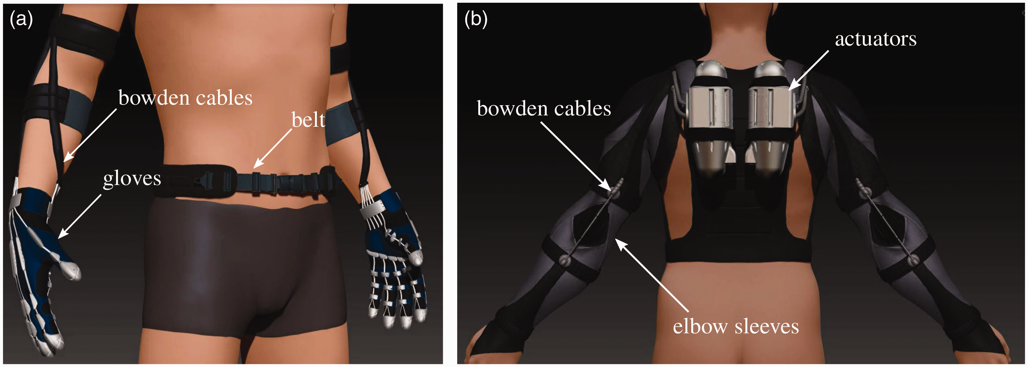
In the following section we define the system requirements based on practical considerations and motion, force and control characteristics. We then detail the structure of the exosuits, and finally present a novel controller that ensures high tracking accuracy despite the uncertainties deriving from the system’s soft architecture.
Design objectives
The lack of previous studies analysing the impact, limitations and benefits of these devices in clinical cases makes it hard to define when they could be most useful. Whilst they have been proven to be effective in reducing the metabolic cost of movement in healthy subjects 28 and delivering improvements in key gait metrics in stroke patients,29,30 no study reports results for the upper limbs in clinical cases. Defining a specific target population for soft wearable robots is, as a matter of fact, still an open question.
In this study we thus assume that our devices will be used for assisting people suffering from muscle weakness and having no major spasticity or contractures (Modified Ashworth Scale (MAS) 0–2). Our design objectives are based on the average dynamic and kinematic requirements necessary to perform ADLs; we have also defined reasonable practical considerations on the weight, size and power consumption of the system.
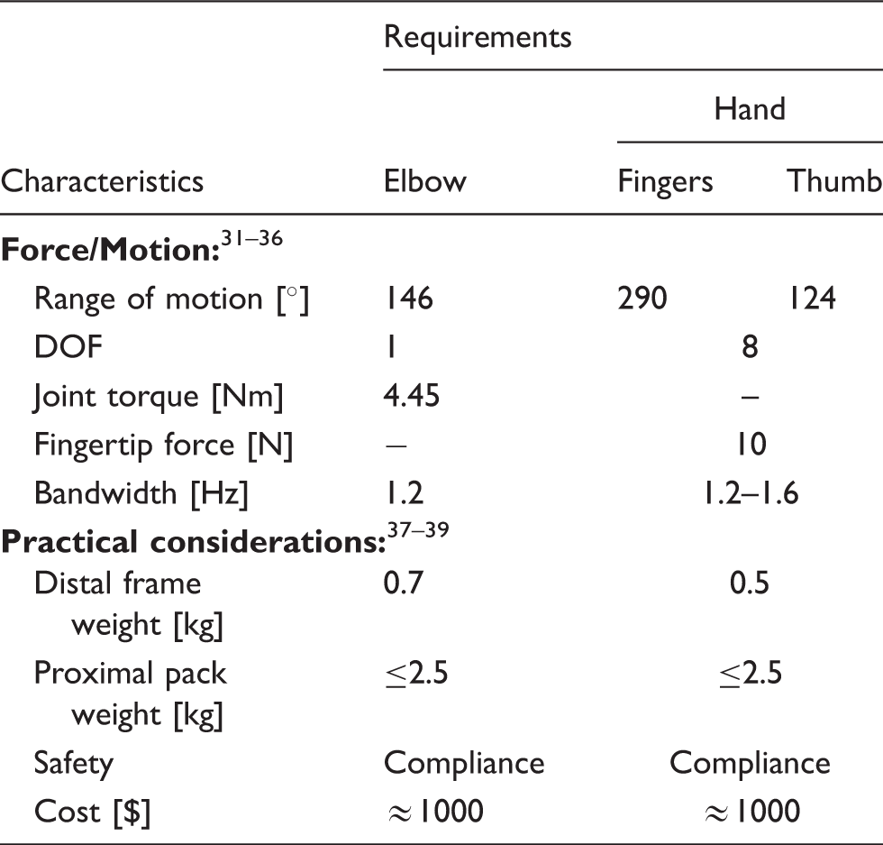
System requirements.
Force and motion characteristic
First of all, an assistive device should have enough DOF to match the ones of the human body. While the elbow only has 1 DOF, the hand is much more complex (21 DOF). Nevertheless, most of the forces in grasping are exerted when flexing the four fingers and opposing the thumb. 40 Extension is equally critical for the pre-shaping phase of grasping, and it is the most weakened movement in hemiparetic patients. 41 For these reasons, we have chosen to actuate only flexion and extension of the index and middle fingers and the thumb (8 DOF).
It is equally important for the device to span the whole range of motion (RoM) of the human joints. Magermans et al. 31 analysed the RoM of the elbow and shoulder in non-impaired subjects, finding a mean of 146° (0° corresponding to the fully extended configuration) for the elbow. A similar study was carried out for the hand by Hume et al. 42 : a total arc (sum of the metacarpophalangeal (MCP) and proximal interphalangeal (PIP) joint) of 124° was found for the thumb and of 290° (including the distal interphalangeal (DIP) joint) for the four fingers.
Finally, many studies have evaluated moments and average speeds of human joints in ADLs. Elbow flexion can require up to 4.45 Nm, with a mean of 1 Nm. 32 Fingertip forces in ADLs are, on average, 10 N, 35 but grasping forces may ultimately reach a maximum of 300 N (female) to 450 N (male). 43 Since the device will operate in parallel with the human muscles, it is not required to reach peak moments or grasping forces; we shall thus refer to their average values.
Lastly, the exosuit should match the velocities of human movements in ADLs. Many studies have evaluated the kinematics of both arm and hand movements, reporting an average elbow flexion velocity of 331°/s 33 and approximately 170 to 230°/s for the joints in the hand. 36 Assuming a sinusoidal motion with a peak-to-peak movement equal to the RoM, these correspond to a frequency of movement of 1.2 Hz for the elbow and between 1.2 and 1.6 Hz for the fingers.
Practical considerations
Portability being one of our main goals, we require the total hand and elbow mounted weight not to exceed 1.2 kg, with a reasonable upper bound for the hand component being at 0.5 kg. 37 This can be easily achieved if the motors, controller and battery are located proximally, for example in a backpack or on a belt at the waist that should not exceed 5 kg.
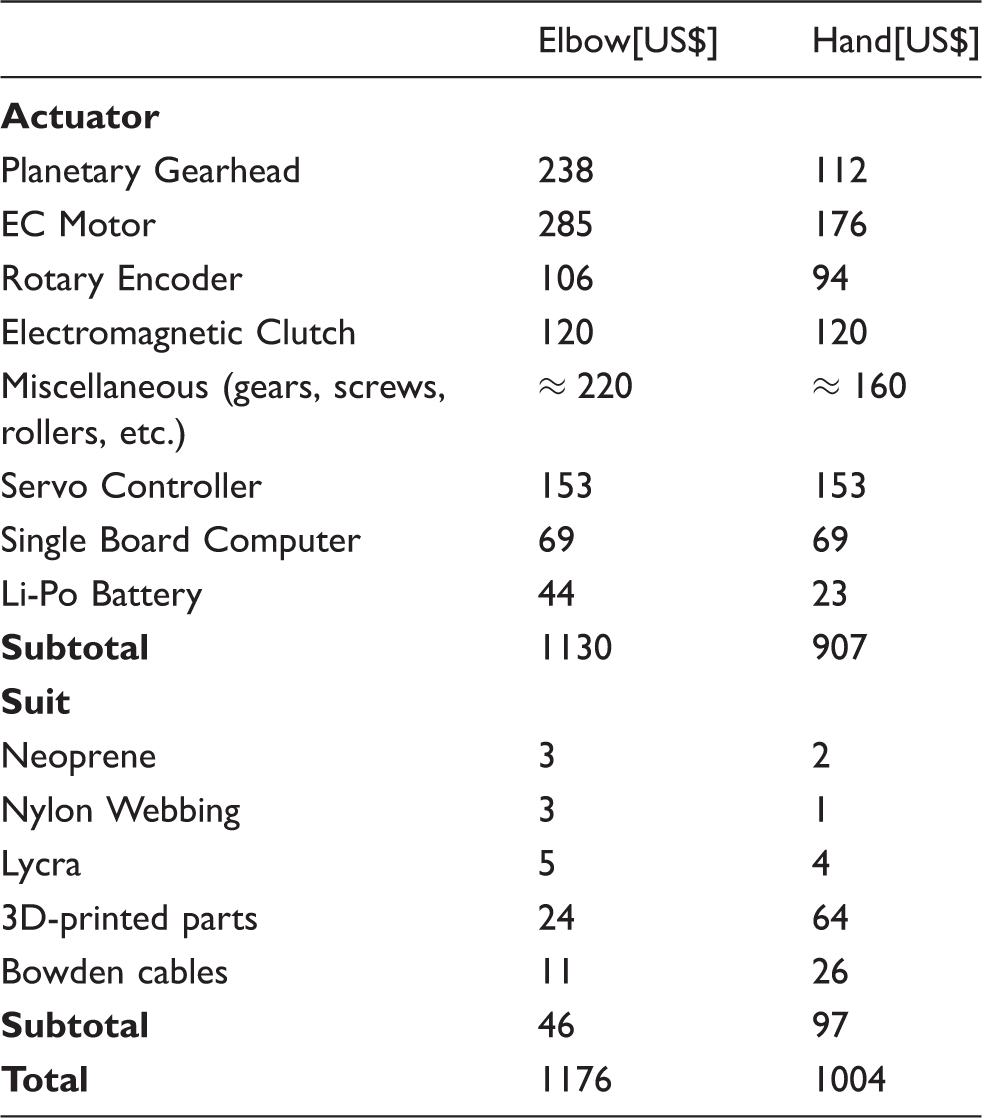
The glove should allow its wearer to perform the grasp taxonomies that better span the posture of the hand in ADLs. Specifically, it should allow at least the basic six grasp types defined by Cutkosky 38 which account for over 85% of the postures used in ADLs, as reported by Jacobson and Sollerman. 39 Finally, the overall cost of each of the exosuits should be kept under 1000 US$.
Mechanical design
The elbow and the hand exosuits each comprise an actuation stage and a wearable component. The actuation stages are located proximally and transmit forces to the suits via bowden cables.
Both motor units can be switched to a low-energy, elastic state by engaging an electromechanical clutch that bypasses the motor and locks the end-effector. Elastic elements in series with the tendons make the user–exosuit interaction compliant, increasing safety, ergonomics and, for the glove, adaptability in grasping. The following sections describe the mechanical design of both actuating units.
Elbow actuation unit
The elbow actuator (shown in Figure 2) comprises the following components: a DC motor (Maxon EC-45 Flat) coupled to a customised planetary gear (reduction of 5:1), a spool around which two cables are coiled in opposite directions, a feeder mechanism and an electromagnetic clutch (Inertia Dynamics, SO11).
CAD rendering of the tendon-driving unit for the elbow suit. A rendering of elbow actuator shows its main components: a rotary encoder (a) senses the angular position of the motor’s (b) shaft. The motor is coupled to an epicyclic gear train (c), with a reduction of 5:1, whose carrier rotates an array of two spools (d) around which the tendons (g) are wrapped. The sun gear can be coupled to the frame by an electromechanical clutch (e), with the effect of locking the elbow in an elastic, low power-consuming state. A feeder mechanism (f) avoids the cables from slacking around the spool.
Figure 3(a) shows a schematised model of the actuation unit. The clutch is coupled to the sun of the planetary gear and can be engaged, bypassing the motor and locking the spool to the frame. This can be achieved with a power consumption of only 5 W. The two tendons are wrapped around the spool in an agonist/antagonist fashion, so that rotation of the motor in one direction causes retraction of the agonist cable and releases its antagonist. The spool is driven by the carrier of the planetary gear, hence the driving torque of the motor and the holding torque of the clutch are amplified fivefold.
Schematics of the working principle of both tendon-driving units. (a) Schematic model of the actuator: the electromechanical clutch operates in parallel with the motor. When engaged, it bypasses the motor and couples the spool to the frame. (b) Operating principle of the feeder mechanism. Each tendon is routed between an idle roller and a one-way clutch. The latter is locked in the coiling direction, impeding the cable from being slack around the spool, but free to rotate in the feeding direction.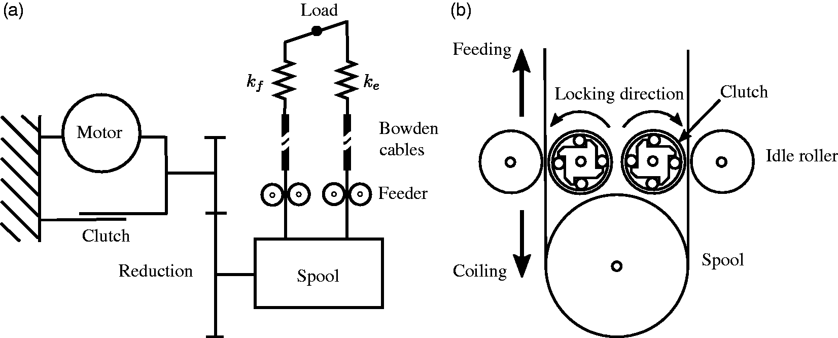
It is important to guarantee that the tendons do not slack around the spool. Pre-tensioning, a strategy commonly used in tendon-driven robots, 44 is not a feasible solution due to the stress that a continuous force would introduce on human joints; rather, we employ a feeder mechanism that confines the slack outside of the actuation unit.
The feeder mechanism (shown in Figure 3(b)) comprises two idle rollers and two one-way clutches. The tendons pass between the rollers and the clutches. The one-way clutches are oriented such that the free direction is the feeding while they are locked when the cables are coiling around the spool. By doing so they introduce a direction-dependent friction in the mechanism: friction is nearly null when the one-way clutch is free to rotate (i.e. when the tendon is released) but is significant when the clutch is locked (i.e. in the direction of coiling). Such friction can be easily be won by the motor, but is enough to impede any slack of the cable from propagating to the spool. In order to increase adhesion, a lining of urethane coating was added on the metallic surface of the clutches.
The two tendons, made of tear-resistant dyneema wire (IGUS Dyneema rope), were routed from the actuator unit on the backpack to the elbow joint through a hollow outer cable housing (Robolink Bowden Cable, IGUS). The whole mechanism is enclosed in a 3D-printed case in ABS plastic. The enclosed design is shown in Figure 5.
Tendon-driving unit for the elbow sleeve. A 3D printed plastic case in ABS plastic encloses the mechanism shown in Figure 2. The total weight of the actuator, including bowden cables, is 878 g. CAD modelling and developed prototype of the tendon driving unit for the assistive glove. The underlying working principle is the same one of the elbow unit, outlined in Figure 3(a). The unit is actuated by a brushless DC motor (b) with a reduction gearhead of 23:1 (c) whose angular position is monitored by a rotary encoder (a). An electromechanical clutch (f) allows to lock the system and keep the hand in place in a low-power state. An array of 6 spools (d), dimensioned according to the first hand postural synergy pulls and release a set of tendons routed through the glove. A pair of spur gears (e) transmits power from the motor to the spool with a reduction of 3:1. A feeder mechanism (g) keeps the tendons in tension around the spools.

Hand actuation unit
The fundamental components of the actuator driving the cables of the soft glove for grasp assistance are shown in Figure 4. Schematically, this unit is exactly like the one for the elbow, modelled in Figure 3(a), with the only difference being that it drives three pairs of antagonistic tendons instead of one. Furthermore, a clutch-based mechanism, similar to the one used in the elbow-driving actuator, allows locking of the transmission and keeping the hand in a desired position with minimal power consumption.
The device consists of a DC brushless motor (Maxon EC-max, Ø 22 mm, 25 Watt) equipped with a rotary encoder (Maxon Encoder MR, 512 CPT) and a planetary gearhead with a reduction of 23:1. A further 3:1 reduction between the motor and the spool shaft ensures the electromechanical clutch (Inertia Dynamics, SO11, τmax = 0.68 Nm) to withstand higher locking torques.
An array of spools, consisting of three pairs of cylinders, drives the tendons routed through the thumb, index and middle fingers in an antagonistic fashion, such that retraction of the agonist causes release of the antagonist. De-railing of the tendons from the spool is avoided using a feeder with the same working principle as the one described in the actuator driving the elbow, and schematically shown in Figure 3(b).
We used Teflon-coated steel cables (Sava Industries, Ø 0.686 mm) as tendons to reduce the overall friction in the transmission and minimise stick-slip phenomena.
45
Finally a 3D-printed casing in ABS plastic encloses the mechanism. The enclosed design is shown in Figure 6.
First prototype of the tendon-driving unit for the soft glove. A 3D-printed plastic case in ABS plastic encloses the mechanism shown in Figure 4 for a total weight, including bowden cables, of 450 g.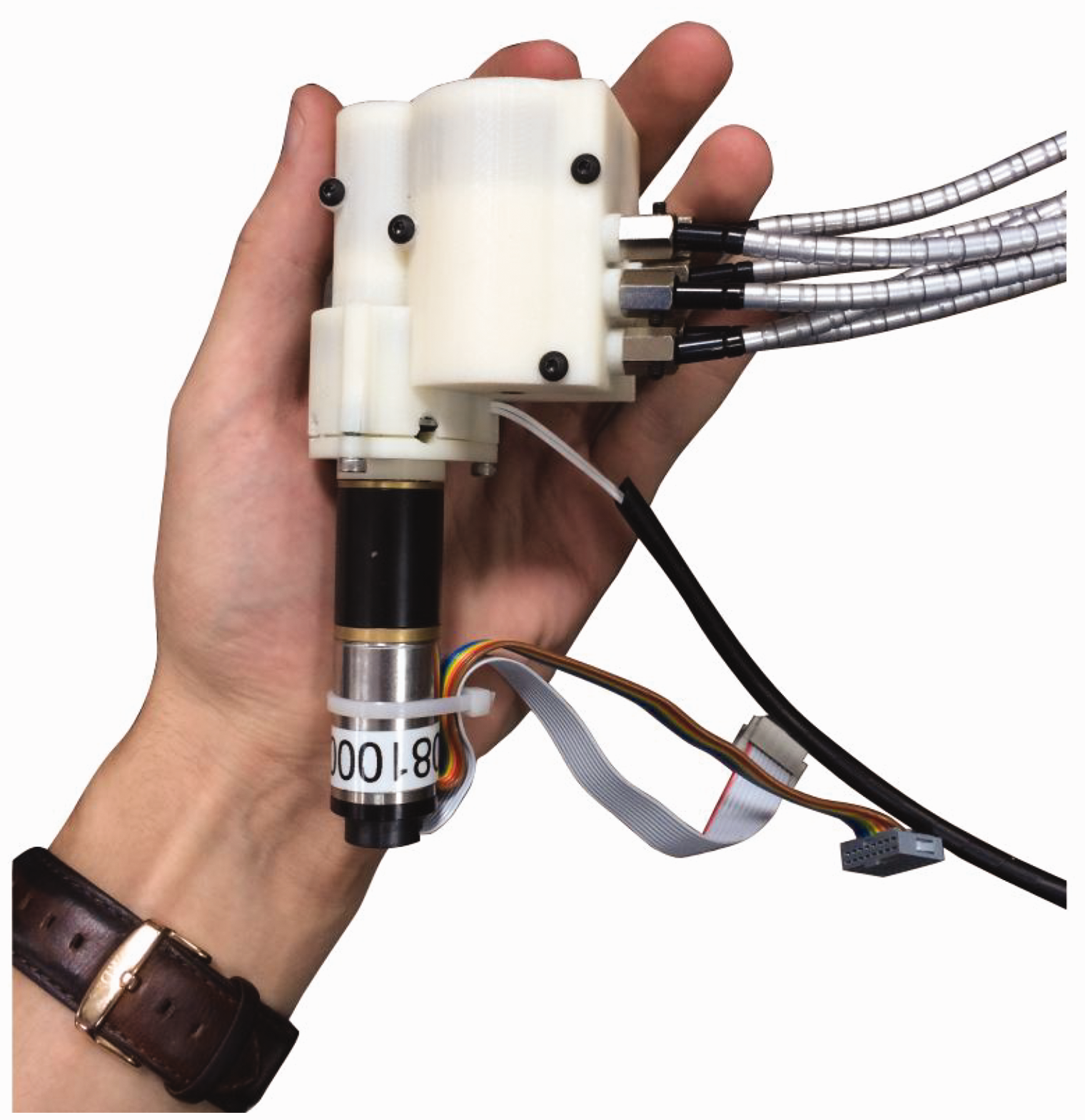
Underactuation strategy
The use of only one motor to move 9 DOF of the hand is driven by the need to simplify the device by reducing its weight, size and power consumption. This comes at the cost of diminishing hand dexterity and impeding independent control of finger movements.
Nevertheless, tasks required in ADLs do not seem to require fine independent control of each DOF of the hand. The human brain, as a matter of fact, relies on a very small set of coordinated hand movements 46 to accomplish dexterous manipulation. These coordinated hand movements, also known as hand postural synergies, define the hand closing patterns that explain most of the variance in ADLs. This finding has been exploited to design underactuated robotic hands that are able to achieve a large range of hand postures with very few motors,47,48 each one activating an ensemble of joints according to a postural synergy.
We utilised the dataset of hand kinematics recorded by Santello et al. 46 and used Principal Component Analysis (PCA) to extract the first postural synergy, which alone explains up to 60% of the variance in everyday hand movements. A mechanical implementation of the synergy was achieved by simply dimensioning the diameters of the spools driving the tendons according to the ratios found with PCA. Finally, to soften the constrains imposed by this synergy and allow adaptability during grasping, the tendons routed in the glove are placed in series with linear springs.
Modelling the tendon routing
In this section we derive the mathematical formulation to map forces in the artificial tendons to torques on the joints. For the sake of simplicity we derive this formulation for one joint only; extending the framework to multiple joints is straightforward.
The way tendons are routed on the joints is shown schematically in Figure 7. The suit has two anchor points on both sides of the joint, made of plastic and inextensible fabric, that act as artificial ligaments, anchoring the suit to the body and allowing transmission of forces. This routing causes the elongation of the flexor to be a nonlinear function of the joint angle.
Schematics of the non-linear tendon routing on the user’s joint. Anchor points are shown in light grey.
Specifically, the extension function h(θ), defined to be the mapping between the joint angle θ and the displacement of the tendons, can be written for both the flexor and extensor, as:


The extension functions are shown in Figure 9 for the elbow joint angle between 0 and 90°. Insufficient release of the antagonistic tendon during motion could cause unnecessary strain on the joint. To avoid this, the diameters of the flexor and extensor spools were chosen to fit, in the least square sense, the difference between Extension of the elbow sleeve tendons as a function of the joint angle. The plot shows the change in length of the flexor (black) and the extensor tendons (blue) as the elbow joint moves form a fully extended position to a 120° flexion. Their difference (shown in red) is non-negligible and would cause significant stress on the user’s joints if not accounted for. By dimensioning the spool accordingly, we can minimise this mismatch (shown in grey). The zero dashed line is shown for reference.
The extension functions can also be used to map the stiffness of the tendons on the user’s joint. This is important to choose the value of the spring constant
If we define 
such that

This term can be used to project the elastic force of the tendons on the wearer’s elbow, thus expressing the stiffness perceived by the user as a result of moving the tendons away from their rest configuration. With the tendons having an elastic constant K, the tension can be expressed as 
This term is shown for the elbow in Figure 8(a), as a function of the joint angle and for three different values of the elastic constant K of the springs in series with the tendons. The obtained stiffness is compared with the range of natural stiffness of the elbow joint during voluntary movements.
49
An analysis of the stiffness of the tendon network for the hand is shown in Figure 8(b) for the MCP joint of the index finger. Values are compared with the biological stiffness of the joint as found by Kamper and Rymer.
50
Modelled stiffness of the exosuit’s tendon network expressed as a function of the joint angle for both the elbow (a) and the metacarpophalangeal joint of the index finger (b). In (a) the perceived stiffness is compared with the natural stiffness of the elbow joint (as found in Bennett et al.
49
) for three different values of elasticity of the spring in series with the tendons. A similar comparison is shown in (b), where the dashed line is the quadratic function describing the stiffness of human finger joints as modelled in Kamper and Rymer.
50

The stiffness analysis of the tendon network was used for an initial choice of the elasticity of the springs in series with the tendons, with a value of 3 N/mm seeming reasonable for the hand unit and 2 N/mm for the elbow.
Suit design principles
The suit is designed to be both comfortable and functional. To achieve these goals, we use a combination of fabrics and components with different elastic properties.
The substrate of the suit, having the function of adhering to the body of the user and keeping it in place, is made of Lycra, a synthetic fibre known for its elasticity. The flexibility of Lycra prevents the suit from constraining muscle expansion during motion and also allows it to fit a larger range of arm and hand sizes. Ensuring a snug fit, moreover, the Lycra substrate tensions the suit around the body, which is important to avoid slipping during operation.
Load paths, that is the directions along which forces are transmitted through the fabric to the body, need to be as stiff as possible to maximise the efficiency of the system. They are thus made of webbing – nylon fibres woven in a flat strip – which is virtually inextensible and able to support high loads. To route the tendons along the load paths, we sewed 3D-printed components on the webbing network on both sides of each joint. These serve as artificial ligaments that anchor the tendons to the body.
A spongy and compressible layer of neoprene was placed at the interface between the anchor points and the skin. This reduces peaks of pressure on the skin and increases comfort. Finally, pre-tensioning the suit against the body, fundamental to avoid slipping and increase transmission efficiency, is achieved via buckles and Velcro straps around the arm and forearm (elbow sleeve), and the wrist (glove).
Elbow sleeve
The first developed prototype of the elbow sleeve is shown in Figure 10. Aside from the components described above, the sleeve was equipped with a rigid elbow protection to prevent the extensor tendon from applying high shear forces on the olecranon process. A guide engraved in the elbow protection keeps the tendon in line with the joint on the flexor/extensor plane. In Figure 10 the subject is also wearing a harness designed to carry the actuation unit on his torso. The harness, that can be tightened through a set of buckles, loads the weight of the device on the wearer’s shoulders.
First prototype of the elbow sleeve. (a) Stretchable fabric. (b) Load paths made of nylon webbing for efficient transmission of the forces applied by the tendons. (c) 3D-printed anchor points. (d) Semi-rigid elbow protection. The sleeve, including bowden cables, weighs less than 200 g.
Glove
A sketch design of the glove is shown in Figure 11. The elastic Lycra layer, in black, forms the substrate of the glove, ensuring a snug fit and keeping the anchor points in place. A neoprene layer, in grey, ensures comfort where the major forces are applied by the tendons. Rings of nylon webbing (not visible) around the phalanxes, beneath the anchor points, allow efficient transmission of the forces to the body.
Design sketch of the soft glove for grasping assistance; dorsal, palmar and lateral view. The glove combines three different fabrics and rigid anchor points to be both comfortable and functional. A substrate in elastic fabric (black) guarantees a snug fit, thus avoiding slipping of the anchor points during operation. A layer of neoprene (dark grey), under the anchor points, avoids the application of high pressures on the wearer’s skin. Rings of non-extensible nylon webbing (not visible) around the phalanxes ensure efficient transmission of forces and anchor points (light grey) route the tendons.
The anchor points, shown in light grey, were 3D printed in ABS and sewn on the fabric. The wrist brace and the fingertip fittings are essential for effective transmission of forces to the body, since they are the only points where forces are applied normally to the skeletal structure. Specifically, the wrist brace loads the protruding trapezium and pisiform bones on the wrist and the fingertip fittings act on the distal phalanx of each finger.
The first prototype of the glove is shown in Figure 12. In addition to the features shown in Figure 11, a pair of Velcro straps facilitate donning and doffing of the device.
51

Actuators’ bandwidth
Both actuators were tested to verify that they meet the velocity required to assist human movements in ADLs, as defined in Table 1. The testing modalities and the set-up used was the same for both tendon-driving units.
We designed a test-bench, outlined in Figure 13, comprising a spool and a rotary encoder, mounted on the spool’s shaft, to sense its angular position. Each tendon, routed through bowden cables from the driving unit to the test-bench, was wrapped around the corresponding test-bench spool and placed in series with a compression spring.
Schematic layout of the test-bench used to evaluate the bandwidth of the desired actuators. The tendons, in series with elastic elements, are attached on a second spool whose angular position is monitored by a rotary encoder. Upon the application of a chirp signal on the motor, we measure the output position and derive the system’s transfer function.
The motor was then excited with a linear chirp position signal of the form:


Data acquisition was performed using a Quanser QPIDe acquisition board at a sampling frequency of 1 KHz; the low-level position control was handled by a Maxon EPOS2 50/5 controller. Figure 14 shows the bode plot of the motor units, extracted using a least square fitting in the Fourier domain. The systems show a bandwidth of 1 Hz (elbow unit) and 8 Hz (hand unit).
Bode plot of the transfer functions of the elbow (grey) and hand (black) tendon-driving units, between the motor position and the end-effector position. The hand unit shows a bandwidth of 51.4 rad/s (8 Hz) whilst the elbow actuator shows a cut-off frequency at 5.96 rad/s (≈1 Hz).
Mechanism specifications.

Control implementation and preliminary results
While the use of flexible materials for transmitting forces to the wearer presents many advantages, it also poses unquestionable control challenges: deformation of stretchable materials, friction in the bowden cables and the viscoelastic properties of human soft tissues make a simple feedback control inadequate for achieving a reasonable tracking accuracy.
A common approach consists in deriving a model-based control law from the dynamics of the system:

From Equation 8 one can derive the feedforward torques uFF required to follow a desired trajectory Control diagram for position control of the tendon-driven elbow sleeve. The adopted control paradigm is designed to follow a given joint trajectory 

Nevertheless, it is extremely challenging to analytically model complex systems like the ones previously described, where non-linear and non-stationary phenomena arise. We thus employed a supervised machine learning regression that approximates, and continuously updates during operation, the mapping from a joint trajectory 
We chose Extreme Learning Machines (ELM) to infer the inverse dynamics of the system because of their good generalisation performance and fast computation time. 52 ELMs are feedforward neural networks with a single layer of hidden nodes where the weights between the inputs and the hidden layer are randomly assigned and never changed. Learning thus involves only fitting, in the least square sense, the weights between the hidden nodes and the targets, which reduces to essentially leaning a linear model.
In our set-up θ represents the elbow joint angle, which we monitored with a low-cost flex sensor (SpectraSymbol 2.2″) sewn in the elbow sleeve, and uff the feedforward control torque sent to motor driving the exosuit. The input data for the ELMs consisted in a three-dimensional vector of elbow position, velocity and acceleration, acquired via the flex sensor, and the target in a value of motor torque. Both the training and prediction stages were continuously performed online with a healthy subject wearing the elbow exosuit and carrying the tendon-driving unit on a harness on his shoulders. The subject was asked not to perform voluntary movements during the trial. Data acquisition and control was done through a Quanser QPIDe real-time acquisition board, with a Maxon EPOS2 controller taking care of the low-level motor current control. Figure 16(a) shows three repetitions of a trajectory-tracking task, consisting of periodic minimum jerks trajectories between 0° (fully extended position) and 90°, with a simple PD control, i.e. Desired and measured elbow joint trajectory (θ) with and without the ELM feedforward term on a healthy subject. (a) Simple position PD control. A significant time delay and amplitude mismatch show that the feedback term alone is not sufficient to compensate for the strong non-linearities of the system. (b) Trajectory tracking with the ELM feedforward term. The amplitude mismatch and the time-delay between the desired and measured joint angle are considerably reduced, with the RMSE on a 20 repetitions trial dropping to 3.67°.
Figure 16(b) shows the same trial obtained by including a feedforward term, continuously updated by the ELM algorithm, in the control law, i.e.
The same configuration was used to test the ability of the ELM algorithm to track a closing pattern of the hand. A flex sensor (Spectrasymbol 2.2″) was sewn for this purpose in the glove on the index MCP joint. In freespace, due to the constraints imposed by the underactuation strategy, one sensor is sufficient to uniquely define a whole-hand configuration.
The obtained results are shown in Figure 17 for five consecutive hand open/close movements, where φ is the index joint angle and 0 corresponds to a fully extended configuration. The tracking performance, in terms of RMSE, is lower than the one obtained for the elbow joint, i.e. 14.98°. This could be explained considering the complex biomechanics of the hand compared with those of the elbow, which limit the degree of accuracy we can reach with our control paradigm.
Desired and measured Index MCP joint trajectory (φ) using the ELM feedforward control paradigm on a healthy subject. The tracking accuracy is lower compared with the elbow due to the complex kinematics of the hand joints (RMSE on 20 repetitions 14.98°).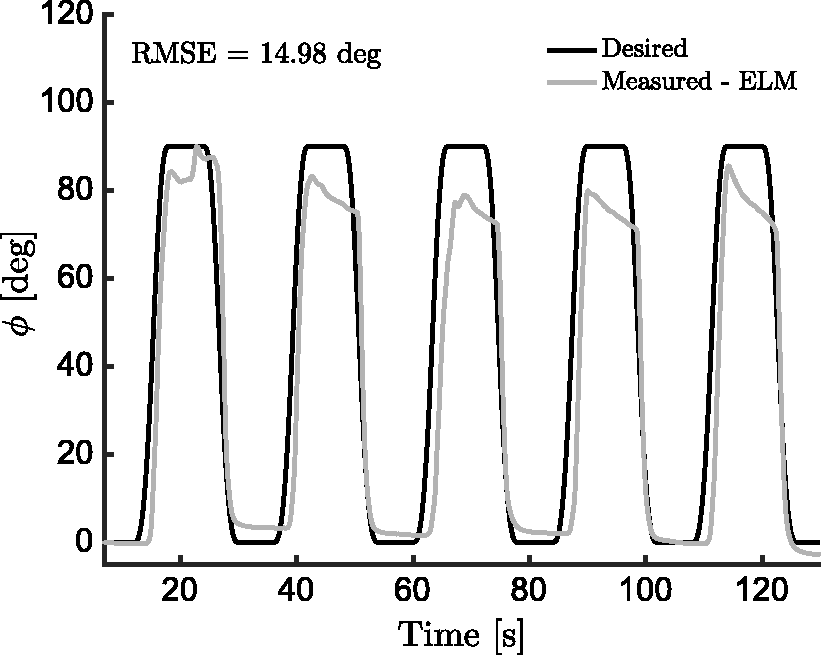
Discussion
Despite the unquestionable advances achieved in the last 50 years in wearable assistive devices, current technologies are still far from being used on a daily basis. This is mostly due to their limitations in terms of portability, safety, ergonomics and, energy-wise, autonomy. Moreover, the cost of most of the developed exoskeletons makes them prohibitive for all but the most affluent users.
In this paper we presented the design and a preliminary testing of a soft wearable exosuit for assisting elbow movements and hand grasping. Using fabrics and bowden cables instead of traditional rigid transmissions would potentially result in cheaper devices, moreover making the device low profile, lightweight, compliant and less restrictive to the wearer’s motion. We based our design on a set of documented force and motion requirements and kept the weight and size of the actuators as low as possible. Finally, we introduced a novel control paradigm that exploits sensory data to learn and refine its model of the system, thus compensating for the non-linear phenomena that make a simple PD control insufficient.
Despite having multiple advantages, exosuits rely on the wearer’s skeletal structure to transmit compressive forces and are thus limited in the amount of assistance they can provide, especially if the wearer suffers from bone weakness caused by disuse osteoporosis, a common co-morbodity of neuromuscular impairments. 58 This suggests that their effectiveness might be strongly dependent on the degree of retained motor ability of the patient. This point needs to be experimentally assessed: to the authors’ knowledge, the only clinical criteria for the use of a soft wearable robot have been defined for the SEM Glove (Bioservo Ltd), which is recommended for patients with and Action Research Arm Test (ARAT) score between 10 and 35 and a Stroke Upper Limb Capacity Scale (SULCS) score of 4–7. 57 We are confident that our glove could prove to be useful for a slightly larger population, since it actuates both flexion and extension of the fingers, whilst the SEM glove only aids gripping strength. No documented criteria, on the other side, exist for deciding the level of impairment that a soft elbow sleeve would be suitable for, thus tests with patients are of paramount importance for identifying the contribution of our technology.
Material cost analysis.
Comparison with similar commercially available exoskeletons for elbow Flexion/Extensio (F/E) and grasping assistance.

*denotes cost of the prototype; †market cost.
In conclusion, whilst there is still a great need for improvement in the design, control and knowledge of their contribution, soft wearable devices for assistance have the potential of becoming a valid and cost-effective solution for increasing independence and quality of life of patients suffering from motor disorders.
Footnotes
Declaration of conflicting interests
The author(s) declared the following potential conflicts of interest with respect to the research, authorship, and/or publication of this article: Patent and invention disclosure “MODULAR AND ENERGY EFFICIENT SOFT WEARABLE EXOSUIT”. PCT Application No.: PCT/SG2016/050383. International Filing Date: 11 August 2016.
Funding
The author(s) disclosed receipt of the following financial support for the research, authorship, and/or publication of this article: This work was supported by Singapore Ministry of Education TIER1, Multi-Nested Myoelectric Control of a Compliant Composite Actuation for Exoskeletons.