
Abstract
Introduction
Physical human-robot interaction offers a compelling platform for assessing recovery from neurological injury; however, robots currently used for assessment have typically been designed for the requirements of rehabilitation, not assessment. In this work, we present the design, control, and experimental validation of the SE-AssessWrist, which extends the capabilities of prior robotic devices to include complete wrist range of motion assessment in addition to stiffness evaluation.
Methods
The SE-AssessWrist uses a Bowden cable-based transmission in conjunction with series elastic actuation to increase device range of motion while not sacrificing torque output. Experimental validation of robot-aided wrist range of motion and stiffness assessment was carried out with five able-bodied individuals.
Results
The SE-AssessWrist achieves the desired maximum wrist range of motion, while having sufficient position and zero force control performance for wrist biomechanical assessment. Measurements of two-degree-of-freedom wrist range of motion and stiffness envelopes revealed that the axis of greatest range of motion and least stiffness were oblique to the conventional anatomical axes, and approximately parallel to each other.
Conclusions
Such an assessment could be beneficial in the clinic, where standard clinical measures of recovery after neurological injury are subjective, labor intensive, and graded on an ordinal scale.
Keywords
Introduction
Rehabilitation robots have become prominent in the clinical research setting for applications in motor recovery after neurological injury. 1 Many research trials have been carried out with these devices, and some improvements in motor scores related to performing activities of daily living (ADLs) have been observed; 2 however, the best way to perform neurorehabilitation is still unclear. This is in part due to a limited understanding of the mechanisms of recovery from neurological injury. 3 In an attempt to increase our understanding of recovery throughout neurorehabilitation, accurate, descriptive, and repeatable assessments are beginning to be investigated.4–8 The only assessments regularly incorporated into neurorehabilitation though are clinical measures,9–11 which are typically subjective, labor intensive, and graded on an ordinal scale. 12 In contrast, robotic measures offer the possibility for objective, efficient, and descriptive assessments.13–15
One compelling robot-aided assessment is the evaluation of biomechanical joint properties, 16 such as stiffness and range of motion (ROM). The wrist in particular is an important joint due to its necessity in performing ADLs 17 and its unique anatomical structure. 18 In a study with cadavers, 18 wrist stiffness and ROM envelopes in the flexion/extension (FE) and radial/ulnar deviation (RUD) plane were discovered to be ellipses obliquely oriented to the conventional anatomical axes. The axis of these ellipses for minimum wrist stiffness and maximum ROM was found to be in the direction of radial-extension to ulnar-flexion, a direction often termed the dart thrower’s motion. Prior studies have estimated the dart thrower’s motion axis, through the axis of least stiffness, to be oriented at an angle of 20–30∘ from extension towards radial deviation.18–20
Studying how stiffness and ROM change over the course of neurorehabilitation could be a promising functional examination of recovery. To perform such an evaluation, an accurate and reliable method for estimating both stiffness and ROM is needed. Multi-degree-of-freedom (DOF) wrist stiffness and ROM measurements have only been measured in a study with cadavers, 18 and the only in vivo 2-DOF wrist stiffness studies have used the InMotion Wrist rehabilitation robot. As a result of limited device ROM, studies with the InMotion Wrist have been confined to evaluating wrist stiffness within 70% of ADL wrist ROM. Additionally, these studies noted limitations on continuous torque output.19,21
In contrast with passive stiffness, maximum wrist ROM has received relatively little attention—though many studies have evaluated ADL ROM through a variety of means.17,20,22 Traditionally, ROM has been estimated with electrical goniometers, 22 but this method can have issues with cross coupling when measuring multi-DOF movements. 23 Another method is to use motion capture, 20 which can facilitate ROM assessment of several joints. A drawback of motion capture is its large physical footprint, non-trivial setup time, and issues with marker occlusion and slipping. On the other hand, a robot is the only platform capable of measuring both stiffness and ROM, simplifying any need for accurate alignment between setups. Such a robot has not yet been realized, possibly related to the fact that the majority of robotic assessments are performed with devices designed for robotic rehabilitation, which has its own design considerations such as inherent backdrivability and generally the goal of supporting ADL ROM.
While wrist stiffness and ROM envelopes could provide new insights into understanding recovery throughout neurorehabilitation, the wrist rehabilitation robots developed thus far do not have sufficient ROM. In this work, the development of the series elastic (SE)-AssessWrist, a novel 2-DOF wrist exoskeleton for biomechanical wrist stiffness and ROM assessment, is described and validated (see Figure 1). The SE-AssessWrist overcomes limitations in using a traditional rehabilitation robot for wrist stiffness or ROM assessment by employing series elastic actuation in conjunction with a laterally flexible Bowden cable transmission and remotely located geared DC motors. The essential features of the SE-AssessWrist are characterized in the context of the intended wrist stiffness and ROM assessments. The paper concludes with a validation study (n = 5) with able-bodied participants, illustrating the potential for wrist biomechanical assessment in the clinic.

(Left) SE-AssessWrist isometric view. (1) Hand attachment point, (2) series elastic FE joint, (3) FE motors, (4) series elastic RUD joint, and (5) RUD motors. The FE and RUD motors actuate their series elastic joints through a Bowden cable transmission. (Center) Device DOFs: (6) FE, (7) RUD, and (8) a passive linear joint for wrist alignment. Wrist FE and RUD are measured through the encoders at the output of the series elastic elements placed on-board the device. (Right) A user interacting with the SE-AssessWrist: (9) open hand attachment through a Velcro strap, (10) elastic element connected to the input pulley, (11) RUD encoder cables, (12), wrist support, and (13) elbow support.
Methods
The following section provides details on the implementation of the mechanical design necessary for performing wrist biomechanical assessment using the SE-AssessWrist. Details on the mechanical design highlight the considerations for meeting the ROM and torque requirements. Additionally, the methodology for experimental validation of the robotic device with n = 5 participants is described.
SE-AssessWrist design
Mechanical and control requirements
To measure user stiffness, a key requirement for the SE-AssessWrist is to be able to move the user’s joint slowly, while also having sufficient torque output and resolution. In previous studies, passive wrist stiffness estimates were carried out by having the robot move at a velocity of approximately 0.1–0.2 rad/s, typically to the limits of the device ROM. Additionally, these studies noted limitations based on the device torque output of 1.95 N ⋅ m.19,21 As such, requirements for the SE-AssessWrist DOFs were set to provide a lower limit on velocity of 0.1 rad/s and 3 N ⋅ m of continuous torque output. The requirement on torque resolution was set to 10 N ⋅ mm to provide sufficient stiffness estimation resolution.
To measure wrist ROM, the robotic device must have a device ROM on par with the human wrist. We estimate an upper bound on maximum human wrist ROM to be 185∘ in FE and 100∘ in RUD.18,24 Note that designing for maximum wrist ROM is a different challenge than designing for ADL ROM, which is the target for most wrist rehabilitation robots.17,25,26 Additionally, during ROM assessment, the device needs to be sufficiently transparent so that a user can comfortably operate the device to explore their own ROM limits. Most wrist rehabilitation robots are inherently backdrivable, but as a result of the cables and motors used for this backdrivability, such devices typically have static friction on the order of 0.1–0.2 N ⋅ m.25,27,28 The maximum target torque to backdrive the SE-AssessWrist in either joint was set to 0.2 N ⋅ m.
Kinematic structure
Since the standard in wrist modeling, and also exoskeleton design, is to place wrist FE as the first axis and RUD second,25,32 the SE-AssessWrist follows this convention with a serial revolute-revolute exoskeletal structure. With this serial structure, the user’s wrist FE and RUD joint angles are measured directly by the output encoders placed at the series elastic actuated joints (see Figures 1 and 2). A passive, and unmeasured, prismatic joint at the handle is also included for wrist alignment purposes. The user interfaces with the device through an open hand configuration, facilitating a natural and relaxed position beneficial to passive stiffness estimation. 21

Bowden cable transmission
To achieve the desired torque and ROM, a Bowden cable transmission was selected. A Bowden cable transmission is advantageous for attaining large ROM while maintaining necessary torque output since a high torque actuator can be housed off-board without affecting joint compactness or mass.33–35 A design trade-off for using a Bowden cable transmission is that it adds friction to the system. This friction can be alleviated partly through careful consideration of materials and Bowden cable construction. Characterization of Bowden cable force transmission has shown that adding a Teflon liner between the cable and conduit increases force transmissivity. 36 As a result, the SE-AssessWrist Bowden cables are constructed from a nylon coated 7 × 19 stainless steel braided cable and a slick lubed inner tubing conduit. To minimize the pretension required on the cables, two motors per DOF are used since pretension increases static friction in the transmission, which in turn negatively impacts control performance.
Series elastic actuation
To estimate torque accurately and to enable backdrivability despite the Bowden cable transmission, the SE-AssessWrist adopts a series elastic actuation architecture.37,38 Similar to Stienen et al., 39 a rotational elastic element was realized with a double Archimedes spiral made from aluminum 7075-T651. The spring was manufactured with computer numerical control machining, which enabled a monolithic design for the spring and hub. The elastic elements (see Figure 2) were incorporated on the exoskeleton frame to provide accurate torque estimation at the output.
To measure spring deflection, US Digital’s EM2 10,000 counts per revolution transmissive optical encoder module with a 50.8 mm diameter transmissive rotary hubdisk was selected and placed at both ends of the spring. This encoder was chosen for its low cost, compactness and ease of use. The encoder leads to a wrist position resolution of 1.57

Quasi-static characterization of the custom rotary spring with a ground-truth torque sensor. The spring rate was estimated to be 75.96 N ⋅ m/rad, which closely matched the finite element analysis prediction of 73 N ⋅ m/rad. Only one spring characterization plot has been included for visualization. Finite element analysis of the spring was performed through a static simulation in Solidworks by placing a fixed constraint at the spring and applying a torque to the pulley.
Motor selection
To achieve the desired torque requirements, Maxon Motor’s RE40-148877 was chosen. Since this motor can output 0.187 N ⋅ m of continuous torque, torque amplification was required to meet the 3 N ⋅ m requirement. To accomplish this, a planetary gearhead with a 43:1 gear ratio was selected. This gearbox can sustain a continuous torque output of 15 N ⋅ m and a peak torque of 22.5 N ⋅ m.
SE-AssessWrist mechanical properties
Device ROM is defined as when the device either makes contact with itself or reaches some physical constraint (such as available cable length). In particular, any serial device that follows the wrist convention of FE carrying the RUD axis will inevitably make contact with the user or itself, which will determine the ROM limits. For the SE-AssessWrist, device ROM is given as two rotational directions (wrist extension and ulnar deviation) in which the device makes contact with itself and in the other two directions (wrist flexion and radial deviation), by the maximum rotation of the human wrist. The device was designed to contact itself in 65° of extension and 60° of ulnar deviation while maximum allowable limits of the human wrist are estimated to be 120° in flexion and 40° in radial deviation.
Continuous torque output was estimated by considering the motor torque constant and gear ratio, as well as inefficiencies in the gearbox (72%) and Bowden cable transmission (85%). 36 The resulting continuous torque estimate is 4.9 N ⋅ m, while the maximum torque is limited by the predicted 5.1 N ⋅ m spring yield torque.
Table 1 compares wrist ROM and torque specifications of the SE-AssessWrist with other wrist robots, all of which have been designed for robot-aided rehabilitation as opposed to robot-aided assessment. An image of a user connected to the SE-AssessWrist is shown in Figure 1. To see the device operating, see our supplementary video attachment.
Range of motion and torque output of the SE-AssessWrist and other prominent wrist robots.
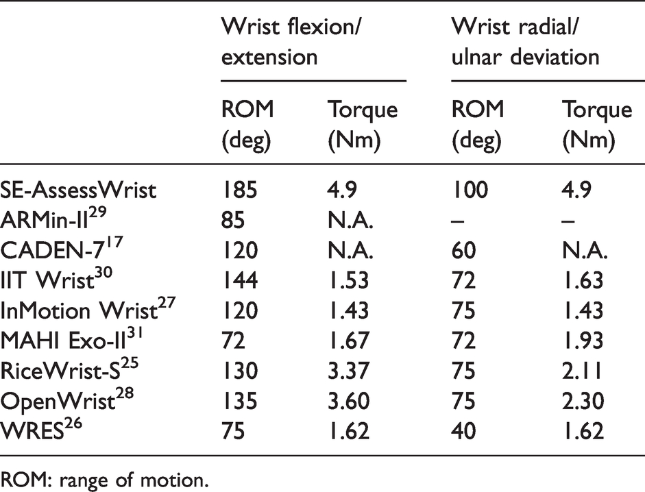
ROM: range of motion.
Control strategy
Stiffness assessment
Wrist stiffness is evaluated by using position control on the robot’s joints to slowly move the user’s wrist while recording the user’s joint position through the output encoders and interaction torque from spring deflection. Due to the use of two motors for a single-DOF, each robot DOF is over-actuated (see Figure 4); however, since the cables only produce rotational motion of the output pulley when under tension, each motor controls a single direction. As such, for the constant velocity needed in the stiffness assessment experiments, each joint consisted of a leader and follower motor. The lead motor was commanded to follow a desired trajectory through proportional-derivative (PD) control while the follower motor was sent a constant negative torque command. This control approach was implemented as follows:
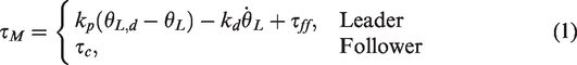

Block diagram illustrating the SE-AssessWrist’s series elastic actuated, Bowden cable transmission scheme.
The feed-forward torque was found experimentally by slowly increasing the motor torque and recording the torque required to initiate movement through the Bowden cable transmission at the output pulley. Feed-forward compensation of friction was found to improve the initial portion of the position control trajectory, as oscillations introduced from backlash and friction were reduced. On the other hand, the follower torque was found experimentally such that it provided sufficient slack in the cable so that the lead motor would not have to overcome friction present in the follower’s transmission.
Range of motion assessment
Wrist ROM is evaluated by measuring a user’s motion with the robot’s joint encoders placed at the series elastic joints while the device is operated through zero force control. Since the SE-AssessWrist is not backdrivable in the traditional sense, the purpose of the zero force controller is to allow the user to more freely explore their wrist ROM while reducing resistance from the device. With a series elastic actuator, zero force control is equivalent to specifying the desired spring deflection to be zero (
As in all series elastic devices, a given DOF cannot regulate lower torque than that of its sensing resolution. Additionally, to overcome backlash, the device’s default state in this control mode is to provide tension on both sides of the spring such that the user can create a torque to inform the controller to perform active zero force control. Once a deadzone limit τdz is exceeded, the zero force controller is implemented. This control approach is given as

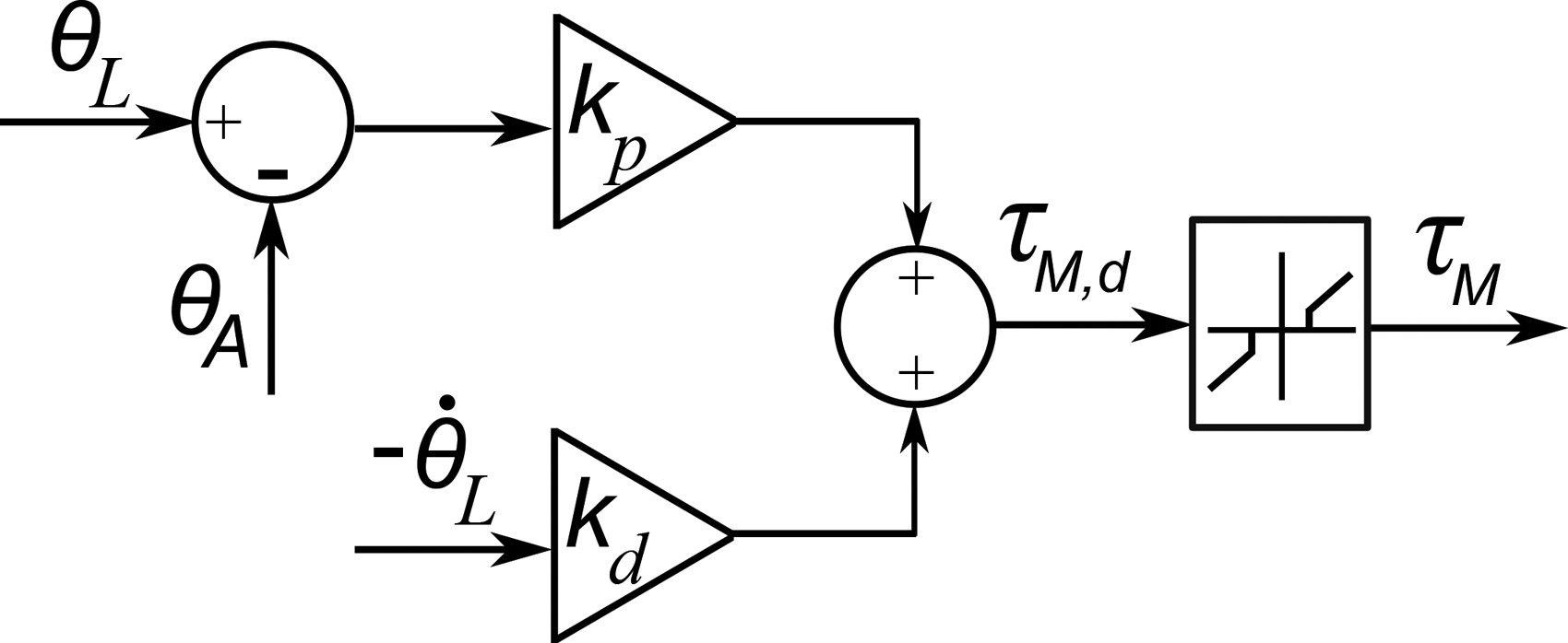
Zero force control block diagram for the lead motor used for backdrivability in the range of motion assessment.
Experimental validation
A validation study was conducted using the SE-AssessWrist to measure 2-DOF active wrist ROM and passive stiffness of able-bodied individuals. Five participants (1 female, 4 male) with an age range of 22-32 years old (mean = 26.4 yr, SD = 4.16 yr) participated in the experiment. All participants were right hand dominant with no current injury or known history of neuromuscular injury in their wrist. Approval for the experiment was obtained through the Rice University Institutional Review Board (IRB-FY2018-331).
Measuring wrist muscle activity
Muscle activity was measured during the stiffness trials to determine if the user’s muscles were passive. To measure activity relating to the wrist, a surface electromyography (sEMG) electrode was placed on each of the four wrist muscles: flexor carpi radialis, extensor carpi ulnaris, flexor carpi ulnaris, and extensor carpi radialis longus. Prior to donning the exoskeleton, participants were equipped with the sEMG electrodes and performed three repetitions of maximum voluntary contraction for both FE and RUD. The maximum signal for each muscle was recorded and used for estimating user passivity.
Wrist alignment
During the experiment, participants sat in a chair with a posture consisting of moderate shoulder flexion, shoulder abduction, elbow flexion, and a neutral forearm orientation. To isolate wrist motion, a cuff was comfortably compressed around the forearm near the elbow. The neutral orientation of the forearm was defined visually with the top of the radial styloid in line with the device’s FE rotational axis. The neutral orientation of the wrist was defined with respect to having an open grasp. As in Crisco et al. 18 and similar to the definitions in Wu et al., 32 neutral wrist orientation was defined visually by aligning the dorsal surfaces of the forearm and hand until flush (FE neutral), and then aligning the third metacarpal’s long axis to be parallel to the forearm’s long axis (RUD neutral).
Range of motion measurement
To find a user’s maximum active wrist ROM, each participant was asked to actively move the farthest they could in a set of 24 directions while the device was operated under the zero force control scheme. Angles chosen aligned with the traditional anatomical FE/RUD axes, and directions spaced 15° apart. Participants repeated the 24 movements 3 times with the directions being presented in 3 blocks. Within each block, the movement directions were randomized to balance learning effects. To assist with finding ROM, participants were presented with a virtual display that contained a cursor identifying the user’s 2D position (

Graphical user interface displayed to participants to facilitate measuring active ROM. The axes and text have been added for visualization.

For ease of visual interpretation, positive was defined as being in the wrist extension and radial deviation directions. Participants were asked to move in the direction of the line as far as they comfortably could and to then return to the origin prior to the next movement. So as to provide directional information while not biasing participants’ ROM movement attempts, the extreme point of the line was a value (150°) that could not be achieved by any participant. Prior to data collection, participants were allowed to practice the task for a few trials to familiarize themselves with the experiment.
Passive stiffness measurement
To measure a user’s passive stiffness, the robot moved the participant’s wrist through position control while the user attempted to remain passive, i.e., to not interact or invoke muscle activity. The wrist was moved by the SE-AssessWrist in 24 equally spaced directions 3 times starting from wrist extension and moving counterclockwise as is standard in the literature.18,19,21 The robot used the user-specific ROM found in the prior experiment as the position limits for stiffness estimation. Since it can be counterintuitive to remain passive while a limb is being moved, participants were given a familiarization trial (approximately 2–3 minutes) prior to data collection. To move the wrist, the robot was commanded to follow a ramp position trajectory (constant velocity) with a velocity magnitude of 0.2 rad/s so as to assist with avoiding muscle activity due to stretch reflex.
To analyze the stiffness data, each movement was segmented. Segments started once the position magnitude was greater than 3° to eliminate any short-range stiffness effects, or oscillations introduced at startup. To avoid using data in the estimate after the robot stopped moving, segments were terminated once the reference position was the final position for a given movement. The linear stiffness of the wrist in that direction, which is the magnitude of the 2-DOF directional stiffness, was then calculated using multiple-linear regression for outbound movements. The position and torque signals were not down sampled or filtered.
Position dependent torques, due to device gravity, encoder misalignment, or conduit flex, were subtracted from the measured joint torques. These torques were characterized prior to the experiment by recording joint torques while the device swept the FE and RUD workspace with a representative mass attached at the handle. Additionally, since the focus of this work is on validation of the SE-AssessWrist, and not biomechanics of the general population, we present results from a subset of the passive wrist stiffness experiment. This subset consisted of trials where the participant viewed a display with their processed sEMG amplitude for biofeedback. They were instructed to try to minimize their sEMG amplitude. Prior to the biofeedback sEMG condition, participants underwent the stiffness experiment without any biofeedback.
Results
Control performance
Characterization of the SE-AssessWrist control schemes was performed through real-time software implemented in a Matlab-Simulink environment communicating with Quanser’s Q8-USB data acquisition board sampled at 1000 Hz. Velocity estimates of encoder positions were obtained through the Q8’s built-in instantaneous velocity estimator. Analog voltage commands from the Q8-USB were sent to servo amplifiers (Advanced Motion Controls AMC 12A8), which converted the voltage commands to current control the brushed DC motors.
Position control
The position control law in equation (1) was evaluated in an experiment without a user. During the experiment, the device made movements to 12 targets spaced evenly in the FE and RUD space. Gains of

Position control performance with low PD control gains to various ramp position commands for the FE (left) and RUD (right). Only three movement portions of the experiment are shown for visualization. While the low gains result in some steady state error, which is acceptable since stiffness estimates are based off of measured joint positions, they more importantly produced the desired constant velocity with lower variance than with higher PD control gains.
Zero force control
The zero force control approach described in equation (2) was implemented while an experimenter moved the device to 12 equally spaced targets in the FE/RUD space. The experimenter moved their wrist at a pace expected during the ROM portion of the validation study. The zero force controller used PD gains of

(Left) The ROM of the SE-AssessWrist (blue, dashed line) was evaluated by manually moving the device within its limits. Plotted for comparison are the ROM capabilities of the InMotion Wrist robot 19 (red, dash-dot line) and the maximum ROM found in the cadaver studies in Crisco et al. 18 (black, small-width dashed line). The SE-AssessWrist ROM exceeds prior rehabilitation robot designs, and is capable of measuring the maximum ROM found in the work of Crisco et al. A user (solid, green line) explored their ROM using the SE-AssessWrist while it was operated under zero force control so that the user could backdrive the device. Forces felt by the user in FE (left) and RUD (right) resulted in a perceived virtual friction due to the deadzone in the zero force controller. The magnitude of this perceived friction is on par with the 0.1–0.2 N⋅m of static friction present in existing wrist rehabilitation robots.
Robotic assessment experimental validation
Active range of motion measurement
From the active ROM measurements, participants’ maximum values were calculated for each movement direction. These values are plotted as a 2-DOF wrist ROM envelope in Figure 10. The mean active ROM measurements in this work are 69.8° in flexion, 53.6° in extension, 48.0° in ulnar deviation, and 30.1° in radial deviation. The axis of greatest ROM found in this study was in the direction of radial-extension to ulnar-flexion, making an angle of 30∘ from wrist extension in the direction of radial-extension. The average completion time for the active ROM experiment was 5 minutes and 56 s.

Results from the (left) active range of motion and (right) passive stiffness experiments. For the range of motion experiment, the dots represent each participant’s maximum directional value. The solid black line is the mean of these maximum values for a given direction. In the wrist stiffness plot, the dots correspond to the average directional stiffness for a given participant over the three trials. The solid black line is the mean of these stiffness values across participants for a given direction. As found in a study with cadavers, 18 the stiffness and range of motion plots are ellipsoidal in shape and oriented obliquely to the conventional anatomical axes. The dashed red lines indicate the axes of greatest range of motion and least stiffness, which are both in the wrist radial-extension to ulnar-flexion direction.
Passive stiffness measurement
Participants’ stiffness for each of the 24 directions was calculated as the average of the 3 measurement repetitions. Stiffness was calculated using only the torque contribution in line with the movement, thus representing the restoring stiffness. The 2-DOF stiffness envelope from these measurements is shown in Figure 10. The axis of least stiffness found in this study was in the direction of radial-extension to ulnar-flexion, making an angle of 22.5° from wrist extension in the direction of radial-extension.
The maximum torque for each participant across stiffness measurements ranged from 0.8 N ⋅ m to 1.5 N ⋅ m (0.3 N ⋅ m standard deviation), while the average wrist torque ranged from 0.19 to 0.31 N ⋅ m (0.05 N ⋅ m standard deviation). Mean sEMG activity across all muscles for all participants was less than 0.67% of maximum voluntary contraction. This sEMG activity is similar to the approximately 1–3% of maximum voluntary contraction found during passive wrist stiffness measurements in Pando et al., 19 providing evidence of user compliance with the instruction to relax their wrist muscles during this portion of the experiment.
Discussion
Both the stiffness and ROM envelopes were observed to be oblique to the conventional anatomical axes. We found that the directions of maximum ROM and least stiffness were aligned with a direction from wrist extension/radial deviation to flexion/ulnar deviation, a direction often termed the “dart thrower’s motion”, and that these axes were nearly parallel to each other. The results are consistent with observations made in a cadaver study, 18 which also identified the obliqueness of the wrist stiffness and ROM envelopes, giving some support to the validity of the SE-AssessWrist for evaluating 2-DOF wrist biomechanics. While this validation study demonstrates the capabilities of the SE-AssessWrist, due to the small sample size used in this work, it does not allow us to make conclusions about the wrist biomechanical properties of the general population. Compared with previous studies that investigated wrist stiffness in vivo with devices designed for ADL ROM,18,19,21 this work includes both wrist stiffness and maximum ROM assessment.
Further merits of our approach include being able to investigate passive stiffness over the user-specific ROM. Previously, ROM estimates have been carried out based on limitations in device ROM.19,21 Being able to investigate stiffness over the user-specific ROM could enable more complete evaluations of wrist end point stiffness, and ensure that the user’s ROM is not exceeded. Additionally, in contrast with the open-loop torque control employed in rehabilitation robots, leading to an estimate of wrist stiffness from motor current, the SE-AssessWrist has direct torque estimation for assessing wrist stiffness. Having a device that can assess active wrist ROM, could be beneficial for providing a ground truth measurement of passive ROM, which could be beneficial for situations in which the user cannot voluntarily move to their limits.
In addition to the experimental validation study, demonstration of device performance for the assessment application was presented in two characterization experiments. Position control experiments highlighted accurate trajectory following despite the Bowden cable transmission. Additionally, since the device is non-backdrivable, an active transparent mode was implemented through a zero force controller to enable wrist ROM assessment. In this way, the device was able to accurately regulate the spring torque to within a small deadzone of 0.15 N ⋅ m, similar to the friction of 0.1–0.2 N ⋅ m found in other wrist exoskeletons.25,27,28 The PD control gains used in the robotic assessment experimental validation were similar to those used in the control performance characterization experiments. Prior to clinical use, control performance should be increased through automated adaptive PD control gains for each user, as well as incorporating a model of the human wrist.
Robot-aided assessment is not the only platform for measuring wrist ROM. Motion capture provides a means for not only measuring wrist ROM, but potentially ROM of the entire body. While it might be possible to study ROM with a passive device or through motion capture, neither solution would offer the possibility of assessing both stiffness and ROM through the same mechanism, which could be beneficial for repeatability, accuracy, and efficiency. By assessing both properties with the same device, wrist alignment can be maintained, allowing for a direct comparison between the two. Additionally, motion capture suffers from issues such as requiring a large setup area, a substantial setup time, and can suffer from marker occlusion and slip. While it might be useful to “calibrate” a robot using motion capture, given the prior limitations, it might be challenging to use ROM from motion capture as a ground truth measurement. Limitations of the developed robot are its larger footprint compared with other wrist rehabilitation robots due to the Bowden cable transmission, as well as the increase in actuators required for each joint.
Although in this work we have focused on the SE-AssessWrist’s potential applicability for wrist assessment, such a platform could enable other research areas. For example, the SE-AssessWrist might be used for biologically-inspired actuation and control paradigms. In particular, the mechanical actuation architecture has similarities to the three-element Hill muscle model, including series elasticity from the Bowden cable flexibility, as well as parallel actuation (cables) and stiffness (series elastic element). The device could also serve as a nonlinear controls platform, which would benefit from a mathematical model of the system. A complete mathematical model of the system is left for future investigations since the focus in this work was on the viability of the assessment approach and not to optimize control performance. Additionally, while the device was designed for the slow movements for estimating passive wrist stiffness, the device is modular, and readily adaptable for other applications—such as a low-inertia yet high-powered system.
Conclusions
In this work, we presented the development, control, and experimental validation of the SE-AssessWrist: a serial 2-DOF series elastic actuated Bowden cable-based exoskeleton. As found through experiments, the SE-AssessWrist has both the necessary mechanical properties and control performance to measure complete wrist ROM and stiffness. Additionally, through an experiment with five right-hand dominant, able-bodied individuals, we confirmed a finding originally reported in a cadaver study—that wrist stiffness and ROM envelopes are oblique to the conventional anatomical axes along a direction of least stiffness and maximum ROM termed the “dart thrower’s motion”. Prior to clinical studies, future investigations should determine the reliability of these measurements through repeated trials comparing estimates from robotic measurements to those made by ground truth sensors.
In the future, this device could be used in experiments with able-bodied individuals to develop a database of nominal wrist stiffness and ROM, which could serve as a reference for wrist biomechanical assessment of neurologically impaired individuals. Such reference data could be appropriately scaled to individuals with wrist sensorimotor control impairments after neurological injury. After the end of an assessment session, the clinician could present the comparison of the magnitude and orientation (e.g. the angle of the “dart thrower’s motion”) of the user’s stiffness and range of motion profiles with the reference set. Using the device to study wrist biomechanical impairment after neurological injury, such as stroke, could reveal insights into the evolution of wrist stiffness and ROM envelopes throughout rehabilitation, which might lead to important insights into the recovery of wrist function.
Footnotes
Declaration of conflicting interests
The author(s) declared the following potential conflicts of interest with respect to the research, authorship, and/or publication of this article: MKO is an employee of Rice University and is a consultant at TIRR-Memorial Hermann. MKO is a co-founder of Houston Medical Robotics. MKO has received grants from NSF, ONR, NASA, NIH, Facebook, and TIRR Foundation.
Funding
The author(s) disclosed receipt of the following financial support for the research, authorship, and/or publication of this article: This work was supported by the National Science Foundation Graduate Research Fellowship Program [Grant No. 1450681].
Guarantor
MKO.
Contributorship
AE and CGM researched literature, conceived, and conducted the study. NM was involved in the design of the wrist robot. AE wrote the first draft of the manuscript. MKO supervised the researchers throughout the study. All authors reviewed and edited the manuscript and approved the final version of the manuscript.
Supplemental Material
Supplemental material for this article is available online.
References
Supplementary Material
Please find the following supplemental material available below.
For Open Access articles published under a Creative Commons License, all supplemental material carries the same license as the article it is associated with.
For non-Open Access articles published, all supplemental material carries a non-exclusive license, and permission requests for re-use of supplemental material or any part of supplemental material shall be sent directly to the copyright owner as specified in the copyright notice associated with the article.