
Abstract
Introduction
This study is aimed at developing a task-based methodology for the design of robotic exoskeletons. This is in contrast to prevailing research efforts, which attempt to mimic the human limb, where each human joint is given an exoskeleton counter-joint. Rather, we present an alternative systematic design approach for the design of exoskeletons that can follow the complex three-dimensional motions of the human body independent of anatomical measures and landmarks. With this approach, it is not necessary to know the geometry of the targeted limb but rather to have a description of its motion at the point of attachment.
Methods
The desired trajectory of the targeted limb has been collected through a motion capture system from a healthy subject. Then, an approximate dimensional synthesis has been employed to specify the size of the mechanism and its location with respect to the limb, while generating the desired trajectory. The procedure for this method, from motion capture to kinematic synthesis to mechanism selection and optimization, is validated with an illustrative example.
Results
The proposed method resulted an exoskeleton which follows the desired trajectory of the human limb without any need of aligning its joint to the corresponding human joints.
Conclusion
A method to design lower mobility exoskeletons for specific sets of human motion is presented; the approach result an exoskeleton with lesser actuation system while generating complex 3D limb motions, which in turn results a lighter exoskeletons. It also avoids a need to align each robotic joint axis with its human counterpart.
Keywords
Introduction
New robot technologies, acting in collaboration with humans, have the potential to greatly increase both productivity and quality of life. One such evolving co-robot technology is the robotic exoskeleton, which attaches directly to a human to augment the abilities of the user. Exoskeletons are being developed for many applications, including medical monitoring and intervention, strenuous and repetitive work, dangerous jobs, and military missions.1–3
For the purpose of industrial and medical application, robotic exoskeletons were studied in the late 1960s and 1970s.4,5 Exoskeletons were also designed to enhance the strength of humans.6,7 Currently, many exoskeleton robots are proposed/designed for the rehabilitation, haptic interaction, and power augmentation purpose.8–11 For more details of recent robotic exoskeleton developments and applications, see Bogue. 12 An ideal exoskeleton should generate natural motions within the workspace of the human limb without causing vibrations or sudden motion changes and without adding extra load or burden on the user. All these considerations make the design of robotic exoskeletons difficult.
The prevailing notion with exoskeleton research and development is that ideally they should be able to reproduce every motion that the human operator is capable of. The common approach in exoskeleton design is to attempt to align each robotic joint axis with its human counterpart (e.g. a rotational joint for the elbow).13,14 For example, the surmised ideal upper extremity exoskeleton should have the same workspace as the human arm. To this end, researchers continue to increase the degrees of freedom (DOFs) of their exoskeletons. In the case of the human arm, excluding the hand and fingers but including the wrist, there are seven DOFs (three at the shoulder, one at the elbow, one at the forearm, and two at the wrist). Adding the hand and fingers adds additional DOFs. As the DOFs increase, so do the complexity, size, weight, and cost of the exoskeleton. Furthermore, good alignment is often difficult and the distances between joints must be adjustable to accommodate the variances of human limbs.
A major practical challenge to the comfort and usability for exoskeletons is the need to avoid misalignment of the exoskeletal joints with the corresponding human joint. Alignment disparities are difficult to prevent due to large inter-user variability and can create large stresses on the attachment system and underlying human anatomy.15,16
An alternative to the rigid exoskeleton is the soft exoskeleton, where mechanical joint axes are omitted and the human limb itself serves as the mechanical structure. Actuators are attached between limb segments to augment the strength of the human subjected. This produces a lighter and less obstructive exoskeleton, but its premier application may be fatigue mitigation; in the case of human augmentation, either for rehabilitation or industrial applications, power amplification requires excessive joint and bone loading.
For some human joints, such as the elbow, the motion of the joint can be fairly accurately reproduced with a common robotic joint (in this case, the revolute or rotating joint). In other cases, however, such as movement of the shoulder through scapula and clavicle articulation, the human body follows a complex motion that is difficult to reproduce, with the combination of revolute and prismatic joints.
Traditionally, exoskeletons are designed in such a way that they try to align with the human joint axes of motion.17,18 It is assumed that the location of the axes can be accurately known, and that such fixed axes exist for the range of motion of the joint or set of joints, which is not always the case. A clear example of the complex kinematic modeling is the thumb, for which precise detection methods such as magnetic resonance imaging segmentation19,20 show that considering fixed rotational axes, especially for the CMC joint, is not a good approximation; see also Chalon et al. 21 Similarly, the human shoulder follows a complex motion, where its center of rotation changes with its own motion, 22 which makes the alignment of the exoskeleton joints more difficult as the location of complex human joints changes.
One of the hypotheses of this research paper is that for many applications, a complete recreation of the human workspace may be unnecessary and suboptimal. In fact, a reduced, sub-workspace may be the best solution. For rehabilitation of the upper extremity, for example, it is likely that a properly designed robotic exoskeleton could achieve a large percentage of clinically desired motions with a greatly reduced workspace. In this research, a systematic design approach is proposed with illustrative examples for the design of exoskeletons that can follow the complex three-dimensional (3D) motions of a human body. With this method, it is not necessary to know the geometry of the hand or the targeted body but rather to have a description of its motion at the attachment points.
In this proposed design methodology, the process is divided into three stages. The first stage uses motion capture to record the kinematics associated with the desired task or set of tasks. The complexity of the data is then reduced through optimization to a workspace that properly characterizes the desired task(s). The goal is to accurately represent the design motions with an optimal set of joints and actuators. This may be thought of as a curve-fitting (regression); we are looking for the proper type and number of basic functions (joints, in this case) to reproduce the desired motions without overfitting the data.
The second stage uses dimensional kinematic synthesis in order to create an articulated system able to follow a specified motion. 23 This stage defines, given the type and number of joints and the loops of the mechanism, the relative position between the joints, which in turn fully specifies the workspace of the mechanism. Several methods exist for the dimensional kinematic synthesis of linkages. Geometric constraints imposed by the joints can be used to define design equations 24 ; robot kinematics equations to reach a set of positions can be stated and solved for both the joint variables and the structural variables.25,26
It is important to note that any dimensional synthesis method used for the second stage can be used to provide the input data (the joint axes and their connectivity) for the third stage. The third stage deals with the optimization of the links to satisfy a set of performance requirements. Many of these additional performances, such as motion smoothness, obstacle avoidance, force transmission, or physical dimensions to name a few, are fully or partially independent of the kinematic task. The optimization stage has been successfully developed, implemented, and tested in several mechanism designs. 27 It is a general method that can be used to optimize different topologies, such as serial chain, closed linkages, linkages with tree structure, and hybrid mechanisms.
The output from the optimization algorithm is used for computer-aided design (CAD) implementation. This helps to have a 3D visualization and simulation of several candidate solutions. The CAD model is also used to check the performance of different actuators and their placement in the mechanism.
The design process
The proposed design process is a task-based and body-adapted methodology, aimed to yield an articulated system composed mainly of rigid bodies and powered by actuators. In this method, the input is the human motion captured using vision-based or similar motion and/or force capture systems, as well as some performance requirements.
The desired motion is used in a finite-position kinematic synthesis stage and yields a set of exoskeleton mechanisms able to follow the desired motion. This stage requires also the input about the mechanism topology. Parallel robots are mostly used as input topology due to their higher robustness, high payload, and lower DOFs, which lead to a lower number of actuated joints.
At this point, several solutions may be obtained, and a manual selection of the candidate or an automatic ranking of the candidates according to their kinematic fitness is required.
Additional performance requirements are enforced on the selected candidate by using a link-based hybrid optimization routine. The selected exoskeleton is further optimized at this stage to ensure motion smoothness, obstacle avoidance, and optimum physical dimensions, among other requirements.
The optimization yields a kinematic sketch in which the link lengths and shapes, as well as the position of the joint axes, are given. This kinematic sketch is then imported to a CAD system for the detailed design of the links and the placement of actuation and transmission components to have a complete design ready for prototyping. The general design process scheme is shown in Figure 1.
The general design methodology. CAD: computer-aided design.
Human motion capture
The desired task has been traditionally specified as a set of finite precision positions that the end-effector of the kinematic chain should pass through. 28 Recent research efforts are directed towards the use of full trajectories 29 or regions of the space that define the workspace. For robotic systems designed for anthropomorphic tasks, the human motion is usually captured with video cameras 30 or infrared technology, as demonstrated in Sigal and Black. 31 In this research, the human motion data have been acquired using a Vicon motion tracking system.
The infrared cameras are set around the room, primarily for larger applications; however, they also work well for smaller size applications, such as hand motions. The markers used in the system are small white balls that reflect the infrared light. For instance, for one of our thumb exoskeleton designs, we used arrays with the markers placed 1.25 inches apart, making it easy to collect 3D data. In order to assess the exact location of the fixed link with respect to the hand, additional sets of sensors are placed on the arm, see Figure 2.
Markers placed on the thumb (left) and data capture setup (middle), and the thumbs proximal phalanx path (right).
The data obtained from the markers are used to estimate the pose, which consists of the position and orientation of the targeted part of the human body. An important aspect of this setup is the geometric arrangement of the markers, which directly affects system performance and usability in computer vision applications.
Figure 3 shows several path variations while doing the same task seen from the reference frame of the motion capture system. One representative path is selected for the design of the mechanism (Figure 4).
The paths of the captured frames including thumb's proximal phalanx, wrist, and forearm, all expressed in camera frame. Selected path for the thumb's proximal phalanx. The red bigger frames in the figure show the selected ones along the path.

The pose obtained from this stage is used as the input to the kinematic synthesis stage in which the design equations are formulated for the selected linkage to fulfill the desired workspace of the human motion.
Coordinate transformation
The image, camera, and global coordinate systems (GCSs) are involved in calculating the point positions with respect to the 3D GCS. Based on the intrinsic matrix of the camera, the relation between the image and the camera coordinate system is established. To express the image in a GCS, extrinsic camera matrices, the relationship between the camera coordinate and global coordinate is needed. Therefore, the motion capture camera runs through a two-step calibration process (dynamic calibration and static calibration) to create both the intrinsic and extrinsic camera matrices. In this study, the T-shaped wand markers provided with the motion capture system are used for calibration.
The motion capture system generates the 3D coordinates of the targets (markers) with respect to the GCS using the data measured with the post-processing program.
32
In order to locally measure all movements of the target points, a coordinate transformation Coordinate transformation.
Kinematic synthesis
Kinematic synthesis theory allows creating exoskeletons able to perform a desired motion regardless of the anatomic kinematic chain that is producing the motion. It is known 23 that, as the number of joints of a serial kinematic chain increases, the number of real solutions, that is, of possible chains able to perform a similar task, increases very rapidly. This multiplicity of solutions helps in selecting a design that can be made compatible with the anatomy of the user.
Kinematic synthesis is traditionally divided 33 into two steps: structural or type synthesis and dimensional synthesis. In type synthesis, the topology of the chain (number and types of joints and connectivity between them) that better fits the task to be performed is selected. The dimensional synthesis step has both the mechanism topology and the desired task as inputs and yields the dimensions and relative location of the mechanism in order to exactly (exact synthesis) or approximately (approximate synthesis) perform the task.
Type synthesis for exoskeletons
The selection of a kinematic topology for a given task or workspace is a research area in which much needs to be done. Some efforts have been done to relate the shape and dimension of a workspace to a particular topology, see for instance, Perez Gracia. 34 Also, some results are being developed for planar curves in which the mechanism is selected according to the fitness to a particular one-dimensional workspace. 35
In the case of human motion, there are two reasons why selecting a topology for an algebraic workspace is a difficult task. The human joints are just approximations of the subgroups of motion, and they become more so when the motion is created by several joints. In addition, the human variability for a simple selected task makes the identification or approximation of the motion to an algebraic mechanism workspace challenging.
In order for a type synthesis stage to be integrated in the exoskeleton design, two elements are needed: an atlas of workspaces corresponding to mechanism topologies and an optimization routine able to fit the captured motion to the algebraic workspaces. Lacking these elements, the selected option for our design method is to pre-select a set of mechanism topologies. The selection may be based on the desired DOFs or on the minimal subgroup of motion containing the desired motion. The shape of the workspaces of the candidate topologies is compared to the desired motion.
As an example, Figure 6 shows the displacements of the thumb's proximal phalanx path as screw axes with a pitch, where the screw lengths are proportional to the pitch. The screw axes of the displacements with their pitches generate a screw hypersurface; each line segment represents a finite motion from a reference configuration of the thumb. This representation has all the information of the motion except for the value of the rotation, which can be calculated independently. This can be compared to the workspace of candidate mechanisms. In this case, Figure 7 shows the same information for a Bricard mechanism, which is a spatial closed chain with one DOF. Comparing these two sets of screw axes reveals that the Bricard mechanism may be a good replacement for the thumb's proximal phalanx, as it creates similar surfaces.
Thumb's proximal phalanx path: screw surface of relative screw axes. Screw workspace for a Bricard mechanism.

Dimensional synthesis for exoskeletons
In order to follow as closely as possible the whole task trajectory, approximate dimensional synthesis is used. In this case, the obtained exoskeleton will not, in general, match the trajectory exactly, but rather the approximation can be controlled by minimizing the distance between the desired task and the trajectory of the exoskeleton. It is well known that there is no Haar measure for spatial displacements; however, in the case of an exoskeleton application, we can consider that the fixed frame is anthropocentric in all cases.
Depending on the type of the mechanism, i.e., serial chain or parallel, the design equations are formed; in both cases, the forward kinematics equations as the set of all positions reachable by the robot are defined by a transformation from the base frame to the end-effector frame. In parallel robots, in addition to the forward kinematics, we may impose loop equations as constraints to be satisfied.
The position and orientation of the end-effector of a robot are defined in terms of its joint parameters and physical dimensions by the kinematic equations. Most researchers use the Denavit–Hartenberg formulation to assign the local joint coordinate frames to define the kinematic equations36,37 or matrix exponentials to define the 4 × 4 homogeneous transformations, giving the coordinates of the joint axes explicitly in the kinematics equations. The joint axes are expressed as lines using Plücker coordinates.
For every joint, i, the Plücker coordinates are given by

This general notation will denote a revolute joint when t = 0 and a prismatic joint when

For a given set of task positions, the goal is to find the dimensions of the robot that can position the end-effector at the given set of task positions. In other words, for each position P
j
, there is at least one joint parameter vector
When dealing with the synthesis of parallel robots or closed kinematic chains, the fact that several serial chains need to follow the same path can be dealt with in several ways. Optimization techniques based on minimizing the distance to the desired trajectory can be accompanied with assembly constraints consisting of inequalities on the loop equations of the mechanism; see for instance, Jensen and Hansen, 38 in order to approximate the closure of the mechanism. Another technique includes designing for entire workspaces of closed chains, such as Batbold Batchimeg and Pérez-Gracia 39 ; however, this approach is currently only available for a few simple mechanism topologies. A third way is to reduce the parallel mechanism to the most constrained serial chain, see Simo-Serra and Perez-Gracia, 40 synthesize for that serial chain and design the rest of the serial chains so that they contain the motion of this one as a subset of their motion. When all serial chains joining the base to the end-effector have the same topology, then synthesizing for one of them allows the exact reach of a finite set of positions for all of them. In all of these methods except the exact workspace synthesis, the kinematic behavior of the system is defined at discrete poses, and no information about the motion from position to position is available. This may lead to an undesired behavior of the system. An extreme case will happen when a singularity is found between the discrete positions being targeted.
A different approach is taken for instance in Soh and Robson 41 in which the human body is considered a kinematic chain and additional chains are attached to it in order to restrain the motion, forming a closed system. This technique is effective for human limbs in which the joints' motion faithfully approximates the motion of a mechanical joint such as a revolute joint. Its results on more complex joints have not been assessed yet.
An exoskeletons mechanism can reduce the performance by adding weight, inertia, and friction to the system. According to Royer and Martin, 42 the natural frequency of the swinging of a body is affected by the mass and inertia of the exoskeleton, which can have important consequences on the metabolic cost and the speed of the body. 43 Compensating inertia through control is particularly difficult due to instability issues. 44 In order to overcome these problems and to fulfill additional performance requirements, such as total length, force transmission, obstacle avoidance, or geometry at a given configuration, a post-synthesis optimization method can be used. 27 This method is based on considering the links of the exoskeleton as anchored to sliding points on its set of joint axes and making the additional requirements be a function of the location of the link relative to the two joints that it connects.
The combination of the kinematic synthesis together with the link-based optimization allows to interactively monitor, control, and adjust objectives and constraints to yield practical solutions for realistic exoskeleton design.
An example of exoskeleton design for thumb motions
The human thumb presents a complex 3D motion that can be modeled, depending on the needed accuracy, with three to four DOFs and using variable joint axes. We postulate that it is still possible to use simplified, low-DOF linkages for assisting, in particular, thumb motions. As candidate mechanisms, we focus on a set of closed, spatial, overconstrained, and non-overconstrained four-bar to six-bar linkages with low mobility that present the desired characteristics for this application; see Waldron 45 and Tsai. 46
The spatial mechanism is to be attached to the proximal phalanx of the thumb. In addition, the designed mechanism is confined to avoid the palmar area of the hand, so as to minimize sensory feedback interference, and to allow the mechanism to be manufactured with minimal size. This, combined with the intended location of the actuators, will allow the device to be constructed with low apparent inertia.
For this example, we synthesize the selected linkage to follow as closely as possible the experimental paths of the human thumb. The overall outline or design approach of the mechanism is shown in Figure 1; however, in this case, the post-synthesis optimization step has been omitted.
The thumb data were acquired using a Vicon motion tracking system as shown in Figure 2. The captured data for several paths of the task, and the selected positions, are shown in Figures 3 and 4.
For the design of the spatial motion, it is sometimes advantageous to work with relative displacements. Each relative displacement expresses a motion of the thumb from a reference configuration, taken as the thumb position at the first frame. Each displacement can be modeled as an axis, plus a rotation about and a translation along the axis. This information is encoded as a screw, where the screw axis is the axis of the displacement and the pitch is the ratio of translation to rotation for that displacement, see Figure 6.
Mechanism selection
In order to accomplish simplicity together with spatial motion under a one-DOF system, an initial set of closed spatial linkages with four to six links and standard revolute (R), prismatic (P), and cylindrical (C) joints have been selected. Some of these linkages are overconstrained, while others are trivial; all of them with mobility equal to one.45,46
In particular, the following four-bar linkages: RC-CC, RP-RP, and RR-RR and the following six-bar linkages: CRR-RRR, RRC-CRR, and Bricard Baker, 47 which is an RRR–RRR mechanism, were selected as candidates. Here, the dash separating joints indicates where the end-effector, or attachment to the thumb, is being placed.
Among the properties of these linkages that are useful for our application, we can cite the one-DOF motion, requiring only one actuator, and topological simplicity while creating a complex motion. In addition, overconstrained linkages have other advantages, such as inherent structural rigidity.
The workspaces of relative displacements of the candidate linkages were plotted and the Bricard mechanism showed the highest match with the set of displacements of the thumb, see Figures 6 and 7. The Bricard linkage was selected for the dimensional synthesis.
Bricard kinematics synthesis
In this section, the design equations corresponding to the Bricard mechanism are presented. Consider the closed RRR–RRR linkage as two serial RRR chains, joined at their end-effectors. The axes are labeled as shown in Figure 9, starting at the fixed link and going around in two ways to reach each other at their end-effectors. The table in Figure 9 shows the constraints among DH parameters in a Bricard mechanism in which a
i
is the length of link i + 1, α
i
is the twist angle between the axes of joints i and i + 1, d
i
is the offset distance at joint i, and θ
i
is the joint rotation angle for A serial chain, its joints axes and desired poses. The Bricard mechanism with its DH parameters and dimensions. The table shows the relations among DH parameters of a Bricard mechanism. Comparison between desired positions (blue frames) and linkage positions (red for the left chain and green for the right chain).


In order to create the design equations, the distance between the displacements of the task and the displacements of the candidate chain is minimized. Equate the forward kinematics of the mechanism (both left and right chain) to each of the discrete positions obtained from the motion capture. If each finite displacement of the thumb is denoted by P
i
, then the design equations are

In these equations, the variables we are interested in are what we call the structural variables, which are the Plücker coordinates of the joint axes at the reference configuration. In addition, the optimization process outputs the angles of the chains in order to reach the thumb displacements. Moreover, the Bricard constraints in terms of the joint axes are
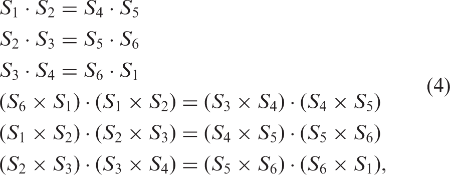
Eighteen positions were selected from the thumb path, and the first frame was taken as the reference configuration. If the forward kinematics is written using dual quaternions, the system is composed of eight equations for each of the two serial chains of the mechanism. This gives a total of 272 nonlinear equations. In addition, we have the constraints (equation (4)) which add 12 equations to the system. There is a total of 284 equations.
The variables to solve for are the Plücker coordinates of the axes (six parameters per axis) and the joint variables to reach each thumb position. Then, the total number of unknowns is 87. This overconstrained system of nonlinear equations was solved using a Levenberg–Marquardt numerical method.
Results
The DH parameters of the resulting mechanism.

Note: Angles are in degrees and distances are in millimeters.
Of these 14 solutions, one linkage was selected based on its overall dimensions and placement on the hand. For this solution, the translational error, which is the distance between the desired and computed end-effector positions, varies from 1 mm to 3 mm, while the orientation error, using Euler angles as a criterion, varies up to about CAD model of the designed robot at the reference configuration.
Prototype
Figure 12 shows the prototype of the Bricard mechanism which was designed based on the proposed methodology to follow the thumb's path.
The prototype of the designed Bricard mechanism with the fixture of forearm attaching to the base.
Figure 13 shows the same mechanism with the hand on it. The mechanism is designed so that the height and orientation of the base are adjustable to provide a good tolerance for different sizes and shapes of forearms and hands.
The prototype of the designed Bricard mechanism with the subject's hand on it.
Conclusions
A method to design lower mobility exoskeletons for specific sets of human motion is presented in this work. With this design approach, the exoskeletons require less actuation to generate complex 3D limb motions, which in turn result in lighter exoskeletons as compared to other designs in the literature. It also avoids having to align each robotic joint axis with its human counterpart, for which the location of the human joint axis needs to be accurately known and fixed in its range of motion, which is not always the case and may cause misalignment.
In this method, real task-based human kinematics data have been used to calculate the dimensions and position of the exoskeleton. The resulting design is non-anthropomorphic, which allows us to locate the joints away from the limb if required. A one-DOF exoskeleton is designed as an example to guide the motion of the proximal phalanx of the thumb finger during a rehabilitation exercise. The resulting design matches the motion of the finger within the desired range, without mimicking the anatomical locations of the human thumb joints. Further work will be devoted to the post-synthesis optimization in order to obtain a more compact solution.
Footnotes
Declaration of Conflicting Interests
The author(s) declared no potential conflicts of interest with respect to the research, authorship, and/or publication of this article.
Funding
The author(s) disclosed receipt of the following financial support for the research, authorship, and/or publication of this article: This work is supported by the National Science Foundation under grant no. CBET‐1403688. The content is solely the authors’ responsibility.
Guarantor
YSY
Contributorship
AP-G, YSY, and ETW conceived the study and wrote the first draft of the manuscript. OH has done the final mechanism synthesis and prototyping. All authors reviewed and edited the manuscript and approved the final version of the manuscript.