
Abstract
The development of full-body exoskeletons has been limited due to design complexities, mechanical integration intricacies, and heavier weight, among others. Consequently, very few full-body powered exoskeletons were developed to address these challenges, in spite of increasing demand for physical assistance at full-body level. This article presents an overall design and development of a powered full-body exoskeleton called “FB-AXO.” Primarily, FB-AXO consists of two main subsystems, a lower-body and an upper-body subsystem connected together through waist and spine modules. FB-AXO is developed for the support of weaker ageing adults so that they can continue functioning their daily activities. At the onset of the project, a set of functional and design requirements has been formulated with an extensive end-user involvement and then used in realizing the FB-AXO. The final FB-AXO design comprises of 27 degrees of freedom, of which 10 are active and 17 are passive, having a total system weight of 25 kg. Overall, the article elaborates comprehensively the design, construction, and preliminary testing of FB-AXO. The work effectively addresses design challenges including kinematic compatibility and modularity with innovative solutions. The details of the mechanics, sensors, and electronics of the two subsystems along with specifics of human-exoskeleton interfaces and ranges of motion are also provided. The FB-AXO exoskeleton effectively demonstrated to assist full-body motions such as normal walking, standing, bending as well as executing lifting and carrying tasks to meet the daily living demands of older users.
Keywords
Introduction
The research in wearable exoskeletons has been increasing over the last few years as the technology advances in personal care robots. 1 –6 Wearable exoskeletons offer useful solutions to the growing needs for assistive technologies. 7 –11 Despite this growth, exoskeleton research has largely been focused on military applications to enhance the load carrying capabilities of soldiers/workers, assisting individuals following trauma and/or spinal cord injury and for rehabilitation needs. 12 Besides military-focused exoskeletons, the majority of research activities has been focused on medical application. 1,13 The needs of ageing society for physical assistance are not sufficiently addressed to utilizing the strong potential in the support of motion. 11,14 This work addresses the possibility of using wearable exoskeletons for ageing to provide general assistance in a natural manner to support activities in daily living. 12,15,16
Full-body (FB) exoskeletons are typically used as human strength amplifiers, where loads are transferred through the exoskeleton, controlled by the human, to the ground. Hence, in the physical interaction with the exoskeleton, only a small part of the load is experienced by the human. As the power is mainly transferred through the mechanical structure of the exoskeleton, the human is able to manipulate loads beyond its natural capabilities. FB exoskeletons are developed to provide comprehensive assistance at body levels, not on single limbs. 17 Examples of such exoskeletons are the Body Extender (BE) 18 or the XOS2. 19 The BE has a quasi-anthropomorphic kinematic structure with a total of 22 degrees of freedom (DoF), all powered by electric motors. Its kinematic structure consists of two identical legs and arms with 6 DoF and 5 DoF, respectively. The BE exoskeleton enables the wearer to manipulate up to 50 kg in each arm and weighs 160 kg excluding the power supply. 18 The system is worn by the user through a set of straps at the feet, two shoulder straps and a belt, and two grippers at the hand. On the other hand, the XOS2 is lighter compared to the BE, with a weight of 95 kg. Like the BE, the kinematic structure of the XOS2 is quasi-anthropomorphic. The system is actuated by 23 hydraulic actuators, where each leg has 6 DoF, each arm has 5 DoF, and the torso has 1 DoF. The system is able to manipulate a payload of 23 kg in each arm. The XOS2 is strapped to the user similarly to the BE, namely, at the feet, waist, upper torso, and with a tool at the hands. 19
Another class of FB exoskeleton is the powered assistive exoskeletons. Instead of transferring the payload from a gripper or tool to the ground, these exoskeletons transfer power between segments of the human limb. Hence, the exoskeleton compliments the function of the human musculoskeletal system, where the assistance level is lower than the counterparts for the strength amplifier type exoskeletons. The most well-known power assistive exoskeleton is the Hybrid Assistive Limb, also known as HAL-5, developed at the University of Tsukuba in Japan. 20,21 HAL-5 is the fifth generation of the HAL exoskeletons and is designed for both rehabilitation and assistive purposes. 22,23 The exoskeleton system is powered by eight electric motors with a reduction gear in the sagittal plane at the knee, hip, shoulder, and elbow. The exoskeleton was able to maneuver 15 kg in each arm and lift and hold a total payload of 70 kg close to the body. 20 Moreover, HAL-5 is fitted with passive joints at each ankle and shoulder. Compared to XOS2 and BE, HAL-5 is much lighter, weighing only 23 kg. HAL-5 has an anthropomorphic kinematic structure and is attached to the user’s feet, shank, thigh, waist, upper torso, upper arm, and forearm, which allows the suit to give assistance at a specific joint.
Other powered assistive FB exoskeletons include the KanaGawa Power Assist Suit 24,25 and Wearable Agri-Robot. 26 The KanaGawa Power Assist Suit was designed to aid nurses in their daily work activities. The system has a total weight of 30 kg and is powered by six pneumatic actuators in the sagittal plane at the elbow, waist, and knee. Moreover, two passive joints are included at each ankle and shoulder. Wearable Argi-Robot was designed for agricultural workers with a total of 15 DoF and weight of 30 kg. Wearable Argi-Robot is actuated in the sagittal plane at the hip, knee, shoulder, and elbow using DC motors and a reduction gearing. Moreover, passive joints are included at the ankle, torso, and shoulder. Like HAL-5, both KanaGawa Power Assist Suit and Wearable Agri-Robot have an anthropomorphic kinematic structure and are attached to the wearer at the neighboring limbs of each assisted joint. In a recent work, a FB exoskeleton for enhancing heavy load-carrying capacities was proposed. 27 The exoskeleton was designed for a maximum 5 kg payload of the upper body and 40 kg of the lower body.
The design challenges for the powered assistive type of exoskeletons are mainly related to the complexity of the human anatomy, 15,28 –30 particularly the shoulder complex and the spine. 6 Exoskeletons are mechanical structures that match the structure of the human body. Hence, the exoskeleton should be able to replicate the kinematics of the human anatomy to as large extend as possible without the exoskeleton colliding with the human or itself. This poses problems for assistive exoskeletons that are attached to each limb segment for the human. A common issue is misalignment that occurs between limbs of the two systems. A mismatch in the kinematics between the exoskeleton joint and corresponding human joint can potentially lead to large human–exoskeleton interface forces and damage the human joint in worst cases. 31 Moreover, it has been shown that the attachment pressure has a large effect on comfort, mental load, physical demand, and effort experienced by subjects. 32 One approach to this problem is to use manually adjustable links, which was adopted by HAL-5, 20 among others. In this approach, the linkage lengths of the exoskeleton are manually adjusted to align the exoskeleton with the human joint. This approach can give good initial alignment but is unable to adjust for possible misalignment during movements. To solve this problem, researchers suggested to use passive joints in the exoskeleton joint design, which maintain alignment between the exoskeleton and the human joints. 29,30 The drawback of this approach is a complicated design and increased inertia and mass. Moreover, for assistive portable exoskeletons, a compact design is desirable. Hence, the exoskeleton design solution should be a trade-off between a compact and lightweight structure with sufficient DoF for the user to comfortably complete a given activity.
The design of a spine module that connects lower-limb and upper-limb exoskeletons is another challenge for FB exoskeletons. Existing designs use either fixed connection like HAL-5 or only one DoF such as XOS2. The limitation with existing designs is that the range of motion (ROM) is considerably constrained, comparing to a flexible spine of humans, which leads to poor interaction between human and the exoskeleton and increased muscle activities.
This article elaborates the design and development of a FB exoskeleton, called FB-AXO, as shown in Figure 1. This exoskeleton was developed in the AXO-SUIT project (www.axo-suit.eu) to address the aforementioned challenges with innovative solutions. It is a medium-duty exoskeleton, designed to support the user in daily life activities such as walking, squatting, standing, bending as well as performing lifting, holding and carrying tasks with objects weighing 5 kg in each arm. The exoskeleton was developed with novel designs of shoulder joint mechanism and a flexible biomimic spine module, which mitigate the issues of kinematic compatibility.
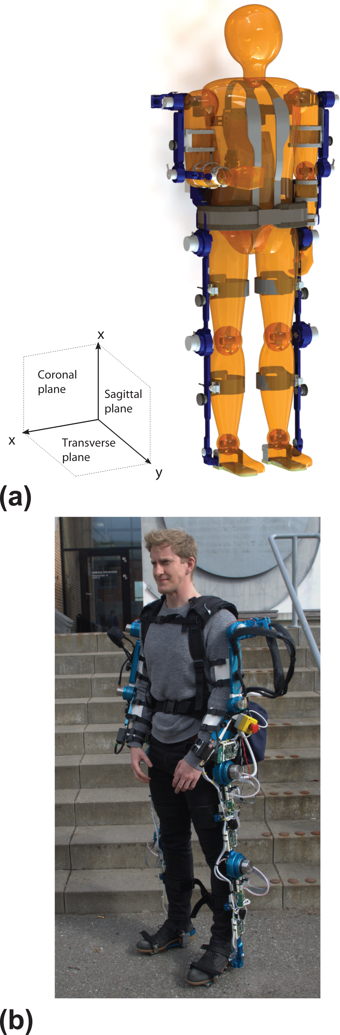
FB-AXO exoskeleton: (a) conceptual design and (b) physical system.
This work extends the authors’ previous work, 33 –35 where the relevant studies and overall FB-AXO concept are presented. In this article, the overall mechanical design is elaborated in details, describing the kinematic compatibility with the human, physical interface design, and force interaction sensor design. A design overview including design requirements is presented in the following section followed by detailed design and construction of the lower-body (LB-AXO) and upper-body exoskeletons (UB-AXO), respectively. Subsequently, initial testing results are described.
Design of FB-AXO from end-user requirements
In AXO-SUIT project, a fully functional prototype of FB exoskeleton namely “FB-SUIT” was designed and developed. The design of FB-AXO has been driven by a high level of end-user involvement. A range of methodologies were used for this to ensure that appropriate end user input was obtained, for example, questionnaires, focus groups, interviews. 36 The extensive involvement of end users right from the beginning of AXO-SUIT project provided vital inputs and feedbacks on both functional requirements finalization and product design throughout the development of the prototypes. The most frequent motions of upper body, lower body, and FB described by the participants of this study were considered as the highest priorities for assistance and are presented in Table 1. 33 The inputs of end users were thoroughly discussed among the AXO-SUIT consortium before finalizing the target motions and incorporating them in the design process. To further validate the practicability of the identified motions and also to facilitate the decision-making process, three-dimensional human kinetic and kinematic simulation data were gathered for these tasks to decide the ROM and torque requirements at joints of the FB-AXO. 37
Highest priority of lower body, upper body, and full body motions, as ranked by questionnaire participants. 36

A specially designed exoskeleton with angle measurement sensors at the hip, knee, and ankle joints of both legs was designed to experimentally measure human walking gait patterns to acquire accurate kinematic and kinetic data. 38 It was found that human biomechanical data of high variability were depended on various internal factors such as age, physical and mental state, and pathological reasons. Therefore, precise sensing and identification of human gait parameters are essential for realizing energy efficient exoskeleton system. The results of the study were used for the design requirements for sizing of the hardware such as link lengths and actuators needed. 38
Therefore, questionnaire results combined with biomechanical data and expert discussions were used to inform the functional goals, design, and technical specifications for the FB-AXO prototypes and are presented in more detail. 36
The FB-AXO design, illustrated in Figure 1(a) along with the physical system shown in Figure 1(b), is developed to provide a moderate supplement of strength at the joint level and is adaptable to wearers of different weights and heights ranging from 70 kg to 110 kg and 1.55 m to 1.8 m, respectively, based on anthropometric measurements listed in Peebles et al. 39 The system has a total of 27 DoFs, of which 17 are passive and 10 active. The ROM of the different DoF is determined based on motion analysis of the movements in Table 1. The active DoFs are linked to movements in the sagittal plane, as the end-user requirements listed in Table 1 are mainly related to motion in this plane. 36 The passive DoFs are introduced to replicate the key kinematics of the human. Moreover, some of the passive DoFs, namely, the DoFs in the passive spine module, contain elastic elements, which allow a certain ranges of bending and twisting motion and also provide additional support to the body.
To make the system reliable, effective, and flexible, a modular methodology is implemented for FB-AXO. The overall FB system consists of two main subsystems, namely, the lower- and the upper-body subsystems, named LB-AXO and UB-AXO. Each subsystem is capable to work autonomously to provide assistance as required. The assistance is provided at joint level through a number of modules. The LB-AXO subsystem consists of two identical legs (left and right legs), each with a hip, knee, and ankle module. It connects to the human via straps at the foot, shank, thigh, and waist. A waist plate, located above the hip joint, physically and functionally joins the two legs. Similarly, the UB-AXO subsystem consists of left and right arms, each comprising of a shoulder and elbow module. UB-AXO also connects to the human via straps at the forearm, upper arm, and torso and waist. The two arms are joined through the torso, which also contains a spine module. The FB-AXO has a total weight of 25 kg, of which UB-AXO weighs 12 kg and LB-AXO make up 13 kg, respectively. The system is powered by a Li-ion battery that can power the whole FB system uninterruptedly for approximately 1 h.
The lower-body subsystem—LB-AXO
The LB-AXO subsystem, referring to Figure 2(a), is designed to support the weight of the wearer and UB-AXO and to provide supplementary assistance to perform a range of basic motions for daily living. The design of LB-AXO is mainly focused to improve modularity, adjustability, ergonomics, and affordability aspects. Consequently, a lightweight prototype was realized, as shown in Figure 3, and successfully tested for users of ages between 20 and 62 (elaborated in the section on preliminary tests).

Conceptual design: (a) CAD model, (b) LB-AXO in simulation software.

The LB-AXO physical system.
LB-AXO module
LB-AXO has a total 12 DoF (4 active and 8 passive). All the active joints are in sagittal plane at the hip and knee modules. Furthermore, the hip module has a passive abduction/adduction and a rotation DoF. The knee module is completely active and has no passive movement DOF, whereas the ankle module is fully passive and has one dorsi/plantar flexion and an inversion/eversion passive DoF. Both of the passive joints of ankle consist of specially designed bolts which have threads at the tip sides to fasten the joint through nuts to allow desired rotation.
From the prioritized list of motions in Table 1, it can be seen that the majority of movement for the LB system is linked to the sagittal plane. Hence, the DoFs in the LB-AXO are primarily related to movements in this plane. As mentioned in the introduction section, a large number of DoFs provides flexibility in motion but introduces complexity in the system. In this regard, motion study was conducted with commercially available 3D modeling software Inventor and Matlab during the design phase of the LB-AXO. The kinematic compatibility between a human model and LB-AXO, illustrated in Figure 2(b), was studied. In the study, the motion pattern is sent from Matlab to the human model, and the exoskeleton model moves along the human model via the kinematic constraints between the two models. In the testing, the load sensors, mounted at the interfaces of thigh and shank, detect the human intention for mobility and the controller power on the actuators accordingly. Therefore, the exoskeleton system moves along human with synchronization.
LB-AXO model from CAD, which includes mass, inertia, joint constraints, and 3D geometry, was imported into Mechanics toolbox of Matlab. SimMechanics toolbox provides a multi-body simulation environment for 3D LB-AXO system. Three cuff-straps were provided on each leg, to hold the LB-AXO with the human leg, at thigh, shank, and foot. The locations of the cuffs and straps can be adjusted vertically and horizontally so that a comfortable fit can be achieved for every individual user. The knee joint was modelled as a single revolute joint allowing flexion/extension motion of the leg in the sagittal plane. The details of the study can be seen in Virk et al. 38 It is noted that the knee joint can also be modelled as a joint involving both rotating and sliding motions, 40 but this also implies a complicated design of joints. 41 We thus consider the knee as a revolute joint to make the design simple and compact.
The selection of active and passive DoF of LB-AXO is determined based on the motion analysis and the results from the previous project EXO-LEGS. 42 As the torque assistance in sagittal plane is dominant, flexion/extension joints of hip and knee are powered by actuators. Table 2 lists the RoM of all joints, which is sufficient to cover the target motion of normal human walking, standing, sitting on a chair, squatting, or kneeling. The medial/lateral rotation DOFs of hip, knee, and ankle joints have a possibility of being passive to improve the performance. Moreover, the dorsiflexion/plantar flexion joint at the ankle can be passive to improve mobility, wearability, and controllability while drastically reducing weight and complexity of the system.
LB-AXO details for hip, knee, and ankle joints. 33

The specifications of the hip, knee, and ankle modules in terms of their actuation and the range of movements are listed in Table 2. The EC series DC motors from Maxon Motor Inc. and the XFS harmonic drive from HAINA are used for active actuation. This drive performs similar to Harmonic Drive but costs only one-third of the latter. The active joints are able to assist with up to 50% of the power required for a target motion, which complies with the low-risk physical assistive robots as defined in EN ISO 13482. The electric motors are mounted with harmonic gear sets with suitable reduction ratio that balances the required assistance torque and human movement speed. Table 3 lists the power, torque, and velocity specifications of the LB-AXO.
Power, torque, and velocity details for LB-AXO active joints.

LB-AXO adjustments and attachments
The LB-AXO subsystem is fitted with wearers using length and width adjustments at the waist, thighs, shanks, and feet, see Figures 2 and 3. The waist support comprises adjustable fastening mechanism around the waist, containing interfaces for the mounting of left and right legs and also provides interfaces to integrate with the UB-AXO through the spine module. The thigh and shank links are adjustable in lengths to fit different heights of the wearers and housing the motors and gear assemblies for the hip and knee joints. The lengths of the links can be adjusted by using sliding links, as shown in Figure 4(a). The foot section is adjustable in length to fit different sizes of feet of wearers. The foot design includes sensors for detecting ground reaction forces. It also comprises of a Velcro belt for attaching the exoskeleton to the shoe of the wearer as shown in Figure 4(b).
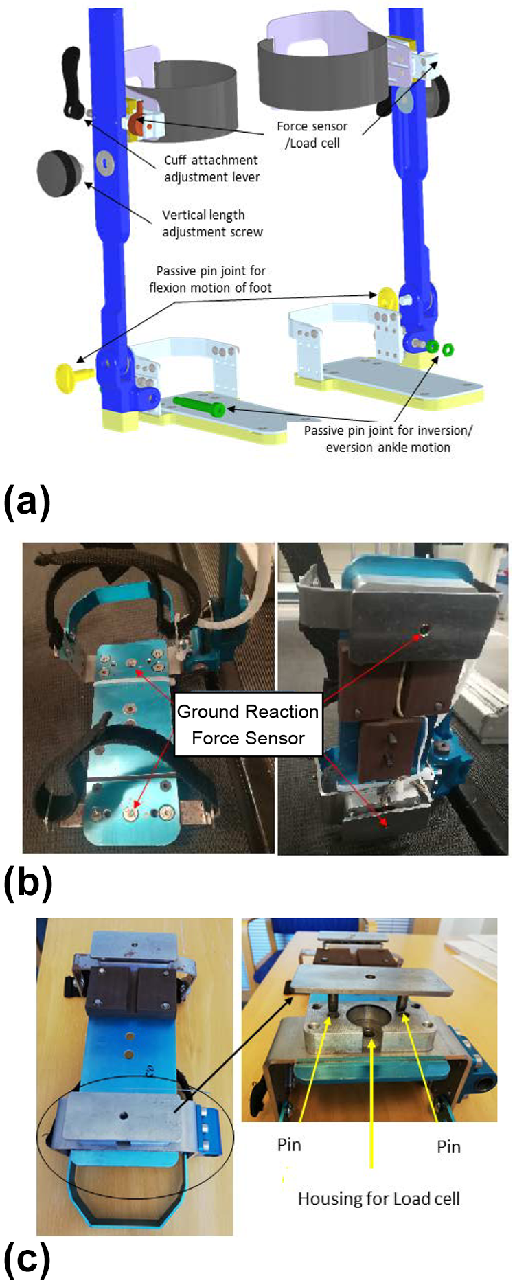
Attachments and force sensors in LB-AXO: (a) CAD model of thigh cuff with integrated minor adjustment and interaction force sensor, (b) foot attachment with integrated ground reaction force sensors, and (c) the pressure plate showing with details.
Another vital aspect in the design of the LB-AXO is the method for effectively mounting the exoskeleton onto the human’s lower extremities with comfort. The appropriate selection of human attachment is vital not only for its wearability but also for the performance of LB-AXO subsystem. LB-AXO directly attaches to the wearer at the waist/upper body, thighs, shanks, and feet. The attachment of LB-AXO and UB-AXO is achieved through the waist support, on which the spine module is mounted. A blast-belt harness, which is normally used for extreme sports and backpacking, is adopted to maximize the adherence level of waist attachment. The blast-belt harness is composed by a soft back with Velcro straps and snap buckle belt for rapidly fitting and easy tightening. This ensures a firm yet comfortable attachment interface.
At the thighs and shanks, an adjustable aluminum strip (front and back) is provided to integrate force sensors. A Velcro belt is used for rapid tightening. The aluminum strip is designed to be adjustable by sliding and locking with a cam slider lever-bolt device as shown in Figure 4(a). It is manufactured by Misumi Inc. and provides comfortable way of adjusting the location of strips with the human body according to the size of the wearer. When the lever is pulled up, it allows movement of the aluminum strip until the user feels comfortable. The lever is then pushed down to lock that position. Furthermore, a soft strip is attached inside of the aluminum strip to improve the comfort and flexibility.
LB-AXO uses a set of different sensors for measuring the state of the system. All active joints are fitted with absolute encoders to obtain the joint angles and thus the system configuration. The active joints are also fitted with angular speed sensors for motor control purposes. There are many different sensors available for measuring force between the mechanical components. In this work, load cells are used to measure the force. Load cells are preferred over other methods to measure ground reaction forces and heel strikes because the other methods (force sensitive resistors, etc.) cannot measure heavy loads. In LB-AXO, load cells (AL31-MM-1C) manufactured by Honeywell Inc. are used to measure the ground reaction force through the foot module. It is important to note that to properly assist the human during each phase of the walking cycle (stance phase, single support phase, and double support phase), each phase’s start and end must be appropriately measured. Therefore, a foot assembly is designed for each leg of the exoskeleton with two load cells as illustrated in Figure 4(b), one at the toe to detect toe-off and the other at the heel to detect heel strike. The load cells are mounted through a separate pressure plate with sliding steel pins to allow proper force application and sensing.
Load cell is sandwiched between the plate and the foot side assembly as shown in Figure 4(c). Two pins are provided on the plate which are located on either side of the load cell housing to ensure vertical alignment as well as to eliminate any motion in the lateral direction. It is noted that the vertical direction component is dominant in calculating the ground reaction force, hence, the lateral direction force component is negligible and was not used in the control system.
The two-plate assembly, on the other hand, provides the necessary freedom to the human for proper walking. Furthermore, the load cells allow proper measurement of the ground reaction forces at each foot of the exoskeleton to estimate the center of pressure which is important in applying advanced stability-control techniques to the exoskeleton. Moreover, the thigh and shank cuffs are also fitted with the load cells to measure interaction forces between the wearer and LB-AXO.
The upper-body subsystem—UB-AXO
The UB-AXO, shown in Figure 5, is designed to support the wearer in activities that require lifting and holding/carrying objects below and above shoulder height, mainly in the sagittal plane. However, these motions also include reaching to the opposite shoulder. Due to these requirements and the large dexterity of the human upper body, the UB-AXO has a total of 15 DoFs, including six DoFs in each upper limb and three DoFs in the spine module. Of them, six DoFs are active and the remaining nine DoFs are passive (Figure 5(a)). Each shoulder module has 2 active and 1 passive DoF, while each elbow module has 1 active DoF. Moreover, the shoulder module is extended with two more passive joints, namely, Joint 1&2-SPR, to account for the shoulder protraction and retraction (SPR). The specifications of shoulder and elbow modules in terms of their actuation and RoM are listed in Table 4, where EC motors from Maxon Motor and harmonic gear from Leaderdrive are used for actuation. The harmonic gear is selected for its back-drivability, which allows the user to move even if the motors are powered off.
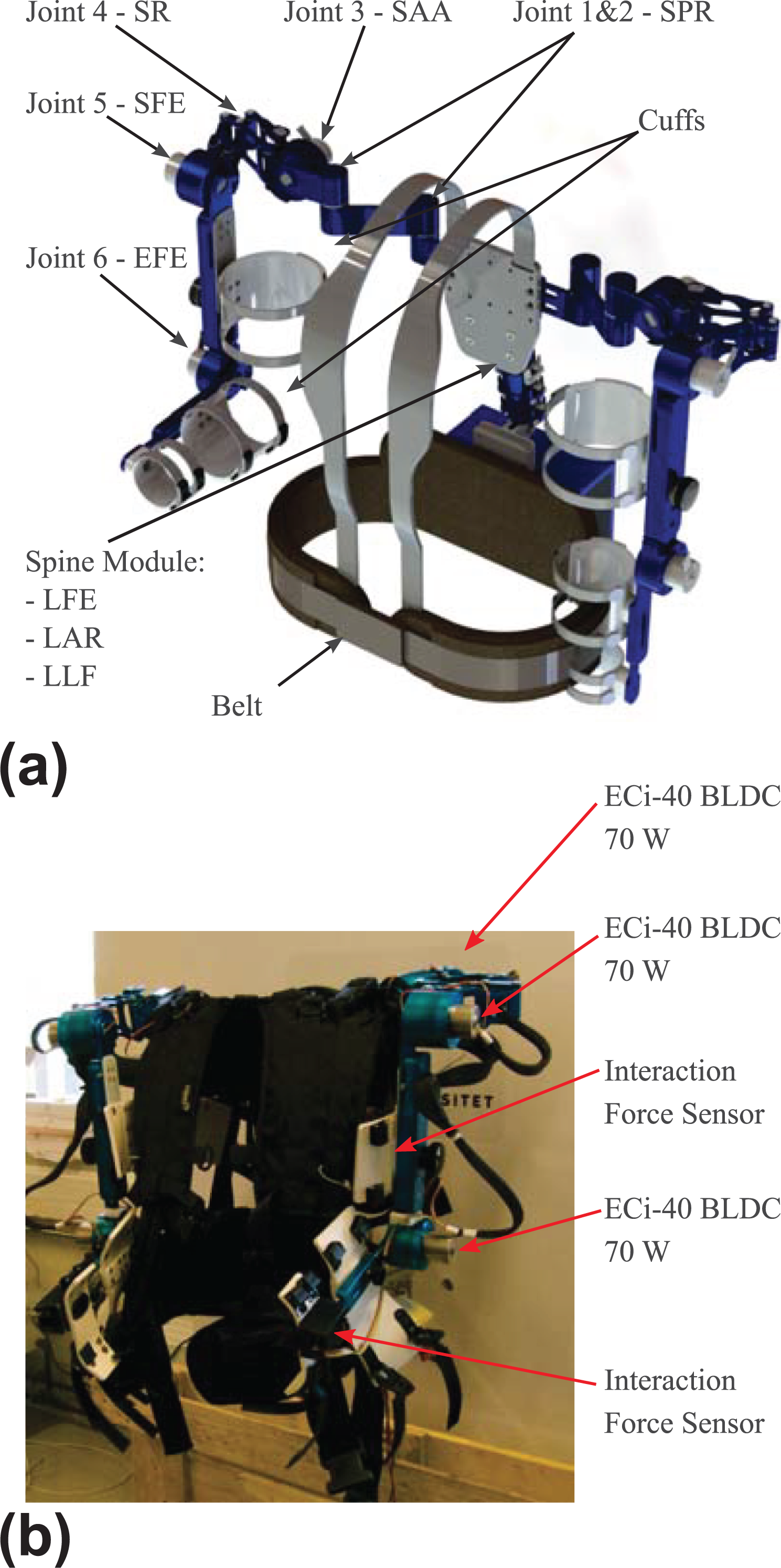
The UB-AXO system: (a) conceptual design of the UB-AXO, where joints 3, 5, and 6 in each arm are active, while other joints are passive and (b) the physical UB-AXO system.
UB-AXO specifications for spine, shoulder, and elbow modules. 33

The shoulder and elbow modules
The shoulder module has five DoF, where two are used to match the protraction/retraction of the human shoulder girdle and the final three DoFs are used to match the three rotational DoFs of the human glenohumeral joint. The shoulder protraction/retraction is realized by two passive revolute joints in series (see Figure 5), as aforementioned. The glenohumeral joint motion is realized by a novel shoulder mechanism composed by two revolute joints connected by a double parallelogram linkage. 43 The double parallelogram spherical mechanism (DPM in short), illustrated in Figure 6, is a remote center of motion (RCM) mechanism with a relatively large RoM free of singularity, which is able to map 90% of the human glenohumeral RoM. 34 Moreover, the parallel structure of the double parallelogram linkage gives the DPM a high overall stiffness, while remaining lightweight and compact. These features make the DPM suitable for assistive portable exoskeletons. The DPM has two active joints and one passive. The shoulder abduction/adduction (SAA) and flexion/extension (SFE) joints are powered, while shoulder internal/external rotation (SR) joint is passive. The elbow module is a single powered joint that supports flexion/extension of the human elbow (EFE). Table 5 lists the torque and velocity specifications of the UB-AXO active joints. All motors have an output power of 70 W.
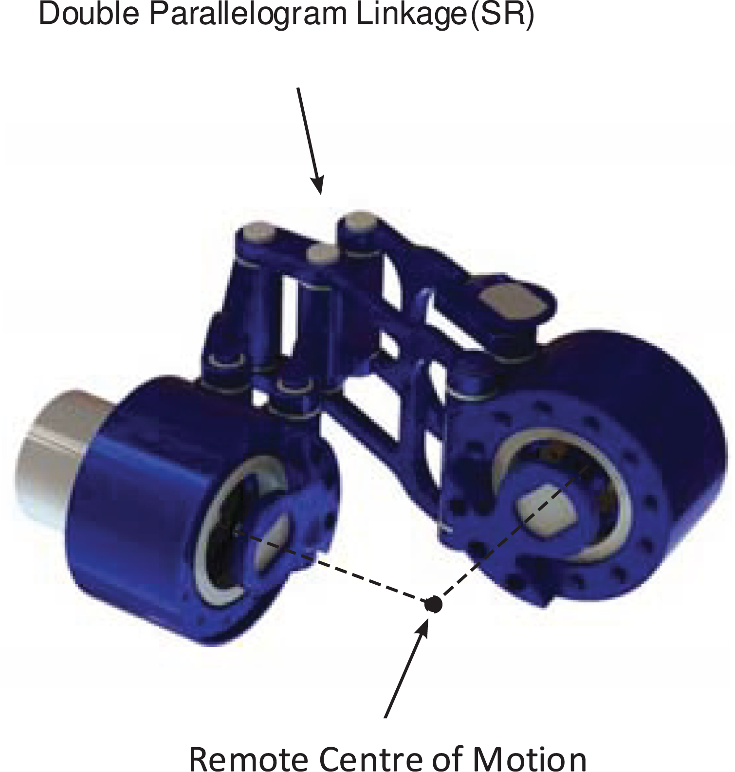
The double parallelogram spherical mechanism.
Motor specifications for UB-AXO active joints.

The spine module
The UB-AXO includes also a spine module, which has three passive DoF supported by compliant elements. The module is designed to transfer the load of the UB-AXO to the LB-AXO and support human upper body, while matching three DoF of the lumbar spine (Figure 7(a) and (b)). The design adopts biomimic approach, with which the spine module is designed to resemble the human lumbar with a set of vertebral bodies of aluminum and intervertebral disks of rubber. The number of vertebral bodies and intervertebral disks used in the spine module depends on the size of the wearer. For the target user group, the number of disks used in the spine module ranges between 3 and 5.

The spine module: (a) conceptual design and (b) flexible motion with the spine module.
The vertebral body consists of two housing units enclosing a spherical bearing to realize three rotational DoF for each vertebral disk. A Teflon bushing is inserted between the vertebral body and intervertebral disk to minimize frictional losses during Lumbar axial rotation (LAR). The RoM of LAR is constrained by end-stops on the vertebral bodies. The end-stop consists of a wishbone structure on the top housing and pin on the adjacent bottom housing, see Figure 7(b).
The lumbar flexion/extension and lateral (LFE and LLR) movements have a spring-backed support by the compliance in the intervertebral rubber disks. By selecting different rubber disks of varying stiffness, the spine module can provide varying supports to users.
The spine module transfers load from the upper body and arms to the legs. Moreover, it provides support to human spine to prevent possible injury caused by extra loads and motion beyond RoM of the spine. Tests were conducted on the bending stiffness of the spine model, as presented in section “Usability testing.”
UB-AXO adjustments and attachments
Similar to the LB-AXO, the UB-AXO is fitted with a set of adjustable links to fit target users. The length of the spine module can be modified by either adding or removing a disk element. Moreover, a sliding adjustment can further be used for fine adjustment. The upper arm and forearm links are both adjustable to fit the wearers arm.
UB-AXO is worn by the user through a set of attachments at the human torso, upper arm, and forearm. A snap buckle belt embedded with a flexible plastics material wraps around the waist of the user and attaches to the base of the spine module. At the top of the spine module, a rigid back plate is fitted with shoulder straps that wrap around the users torso and are attached to the belt. The belt and shoulder straps enable a quick fitting and easy tightening to the user. The upper arm and forearm links are fitted with a set of cuffs consisting of flexible plastics materials tightened to the limb using straps.
UB-AXO uses a number of sensors for measuring both the exoskeleton state and also the human–exoskeleton interaction forces. The SAA, SR, SFE, and EFE joints are fitted with absolute encoders to detect the joint angles and thus the system configuration. The active joints, namely, SAA, SFE, and EFE, are also fitted with angular speed sensors for motor control purposes.
In the design, the upper arm and forearm cuffs are fitted with strain gauge-based force sensors (see Figure 8(a)) to measure interaction forces, noted by

The strain gauge-based interaction force sensors in UB-AXO: (a) force sensors integrated in UB-AXO, (b) strain gauge placement on the UB-AXO force sensors, (c) Wheatstone bridge circuit for the UB-AXO force sensor.
The force sensors are designed with two flat beams with an equal distance to the centerline, as illustrated in Figure 8(b). A total of eight strain gauges are configured in two full-bridge configurations that measure bending moment in the two beams. The first full-bridge (SG11, SG12, SG13, and SG14) measures the force applied along the z-axis at the cuff interface, while the second full-bridge (SG21, SG22, SG23, and SG24) measures the force along the y-axis. The Wheatstone bridge configurations for the two force readings are illustrated in Figure 8(c), where Vs
is the excitation voltage and Vo
is the sensor output voltage. Because the sensor output voltage is low (in the size of mV), an amplifier circuit built with an IC chip, namely, LM324, is used to scale the output voltages for better readability, in which the gain of amplification is determined by
System development and preliminary testing
The FB-AXO has been constructed, as shown in Figure 1(b), with controllers developed. Upon the system developed, the AXO-SUIT was preliminarily tested. 35
Control strategies for the LB-AXO, UB-AXO and FB-AXO in the initial testing
In assistive applications of active joints, the assistive torques are determined through a control strategy that uses inputs from the system, as illustrated in Figure 9.
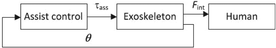
Control strategy, where θ stands for joint variables and
In UB-AXO, a static load compensation strategy is adopted. The assistive torque of each active joint is calculated with three parts; an exoskeleton gravity compensation torque

where

where
Considering that the accelerations and velocities of the human movement are assumed small, the interaction between the human and exoskeleton can be considered quasi static. In this light, a control strategy with gravity compensation is sufficient for the assistance of activities in daily life.
The LB-AXO subsystem adopts a distributed control scheme to take the advantage of separated functionality of each control module. The distributed control can mitigate the computational burden at the specific microprocessor. Therefore, each leg has a powered revolute knee and hip joints which are locally controlled by four CAN-based motor power drives connected to respective slave controllers. All the four slave CAN controllers are connected together through a master CAN controller. Each of the four slave controllers locally handles the sensor input and motor command output and performs data sharing with the master software via CAN bus. Figure 10 shows the joint level control scheme by the slave CAN controller. Each LB-AXO joint assembly primarily consists of a brushless DC-motor as joint actuator, a harmonic drive as gearhead, and an encoder (2 channels MILE 1024) as a joint speed sensor. The inductive MILE encoder ideally complements brushless motors. It offers an impressive resolution and high accuracy. The encoder with inverse signals is very resistant against magnetic and electric fields as well as dirt. It is integrated directly into the motor. The position of each brushless DC motors was locally controlled by EPOS4 Compact 50/15 CAN controller.
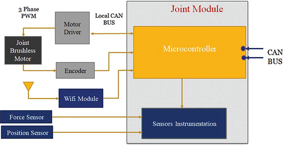
Schematic of joint level control by slave controller.
The master controller not only connects and processes the data from slave controllers but also provides communication GUI link between human user and the LB-AXO as shown in Figure 11. For the LB-AXO system, a force-based control strategy is used, which functions on human–exoskeleton interaction. The force/torque sensors mounted at the interfaces with the wearer (the thigh, shank, and foot attachments) detect the intentions of the human and communicate this to the control system of LB-AXO which, in turn, provides the desired assistance by running the actuators accordingly.

Flow diagram of joint level (Slave)-Master microcontroller system of LB-AXO.
The ranges of motion of hip, knee, and ankle joints of both legs of the model are constrained according to the counterparts of human segments. To simulate the ground reaction forces, foot is represented as rigid body connected by a pin joint, to allow movement in sagittal plane, and contact forces are used between the foot and the ground at estimated times of the heel strike, the single stance phase, the toe off and over the double stance phase. The master controller connects, synchronizes, and provides a central control of the whole system. The details concerning control equations used in the control system design can be seen in a separate study. 38
Usability testing
Tests were conducted to assess the performance of the system. The purpose of usability testing is to examine how usable the FB-AXO is, considering its size adjustability, comfort, and ROM in different poses. Prior to testing at the FB system, each module was tested to function properly. Figure 12 shows the bending curve of the spine with three types of rubber disks, obtained experimentally with a fixed maximum torque. The flexibility of the module enables a natural and comfortable interaction between FB-AXO and human trunk. Meanwhile the stiffness can be adjusted with respect to working conditions. For example, hard rubber disks can be used if the exoskeleton is intended to assist carrying heavy loads.

Bending moment/angle curve for the three intervertebral disks of (1) hard, (2) medium, and (3) soft rubber. While all disks show nonlinearity in stiffness, the hard disk displays only its linear part in the range of applied bending torque, due to its high stiffness.
In usability tests, the participants were asked to complete a set of basic movements related to the prioritized list of motions in Table 1. Tasks for UB-AXO include lifting, lowering, and carrying, while for LB-AXO the task is to walk on treadmill. The tasks for FB-AXO performed include carrying a payload while walking, standing stably in free space, walking up/down stairs, and so on. Figure 13 depicts the usability testing of walking with 6 kg load on a treadmill at a speed of 1.2 m/s. The assistance level was kept constant over the complete interval. A harness on the ceiling was used to protest the user from falling for safety. In total, 24 healthy persons (12 in UB-AXO, 10 in LB-AXO, and 2 in FB-AXO) of ages between 20 and 62 have participated in the usability test separately.

Testing of FB-AXO on carrying payload while walking on treadmill.
Questions asked include whether they feel comfortable in different poses and also feel support to carry the load. Participants provided positive feedback, which demonstrates FB-AXO’s usability to fit and assist users in these tasks. On the other hand, it is also noted that participants feel not easy to put on and take off the exoskeleton and need others’ assistance, which could be further improved through engineering design.
Physical assistance testing
Tests were performed for UB-AXO in load carrying assistance, including lifting, lowering a 6 kg payload (Figure 14). In addition, testing includes also a task of carrying the 6 kg payload while walking.

Test of the UB-AXO with 6 kg payload lifted from the ground to a table.
The users are fitted with EMG sensors at the larger muscle groups, including the biceps and deltoid muscles, to record the muscle activities with/without exoskeleton assistance. The selection of muscles was made following European recommendations for surface electromyography for the non-invasive assessment of muscles (SENIAM, http://seniam.org/). Surface EMG data for all tasks were recorded using the four-channel NeXus-10 MKII hardware and BioTrace+ V2017A software (Mind Media B.V., Netherlands). The EMG data were normalized with respect to maximum voluntary contraction (MVC).
Table 6 presents muscle activities recorded by EMG for two scenarios of the carrying task, one to carry 6 kg payload for 1 min (Carry-M1), the other for 3 min (Carry-M3). The effect of physical assistance can be observed from the data recorded. It is also interesting to notice the difference of assistance effect for the cases of using exoskeleton for 1 min and for 3 min. In the latter case, the assistive effect is more obvious. An explanation to this result is that human users need time to “learn” how to get assistance from exoskeleton. With the current control strategy, the exoskeleton system is not fully adaptive to the given assistive tasks. But once human users learned how to use the system, they can effectively take the advantage of exoskeleton for assistance. This results thus demonstrate also mutual adaptation in the human-exoskeleton interaction. 46 In general, the test results are mixed, showing an overall positive assistance with most tasks. 35 Figure 15 plots variation of interaction force during load carrying. For the 6 kg payload, or 58.8 N, carried by the system, it is observed that roughly 10 N force applied on single human arm, therefore about 20 N force on both arms. In other words, most payload was carried by the exoskeleton, a strong evidence of physical assistance generated.
Muscle activities (RMS Amplitude) in load carrying.


Interaction force during 6 kg load carrying
The performance of the AXO-SUIT was also assessed by Rating of Perceived Exertion (RPE), 47 which is the numeric estimate of subject’s activity intensity. The RPE was measured for participants using a scale from 1 to 10, representing from very light to very heavy perceived exertion. The scores of RPE assessment of UB-AXO module are listed in Table 7, which indicates slightly decreased scores, reflecting the effect of physical assistance by the exoskeleton.
Ratings of Perceived Exertion (RPE).

It is noted that the performance assessment of exoskeleton systems is a very challenging task, which requires well-defined protocols and assessment criteria, and performance metrics. 48 While the preliminary tests on FB-AXO show its positive effect on assistance, more study is needed to test the system and assess performance comprehensively.
Conclusions and discussion
In this article, the design of a modular FB powered assistive exoskeleton FB-AXO is presented. The design challenge of kinematic compatibility between user and exoskeleton was addressed through a close end-user involvement. Questionnaires on functional requirements lead to a prioritized list of upper-, lower, and FB motions to assist. A further study of these prioritized motions was done to determine dominating DoFs, the ROM, joint torques and velocities, and so on.
In this work, a novel exoskeleton is designed with two innovative mechanisms: the DPM shoulder joint and biomimetic spine module. The DPM shoulder joint has a high overall stiffness, while being lightweight and compact. The biomimetic spine module transfers loads from the UB-AXO to the LB-AXO with three quasi-passive DoFs. Moreover, it increases the dexterity for upper-body activities allowing the user to complete complex motions, such as reaching to the side overhead/opposite shoulder.
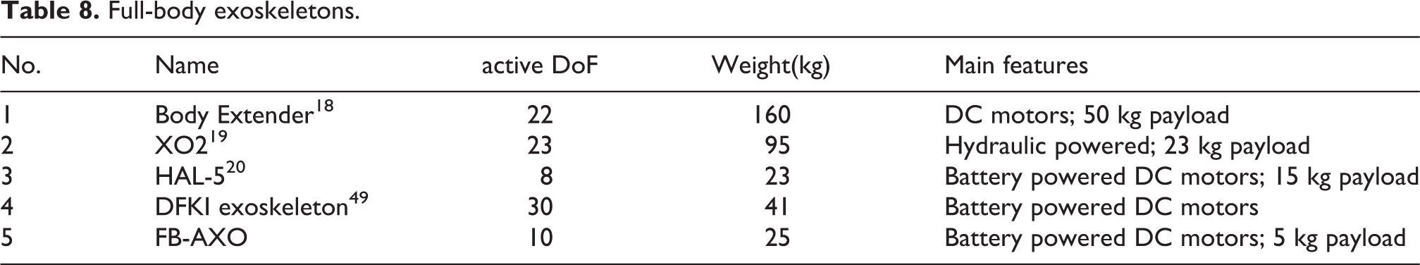
FB-AXO features a high number of DoFs and adjustments to bring higher kinematic compatibility and physical comfort to the user. Compared with other FB exoskeletons, such as HAL-5 and XOS2, as shown in Table 8, the FB-AXO has a low weight, while provides mid-duty comprehensive support that are suitable for physical assistance of the elderly.
Full-body exoskeletons.
Results from the preliminary studies, including the usability and functional tests, of the FB-AXO prototype show a good compatibility between the user and exoskeleton and positive effect in physical assistance. On the other hand, the preliminary test reveals also some limitations of the design, which include the considerable weight and also misalignment due to different subject sizes. Moreover, control of human–exoskeleton systems for upper-body exoskeleton applicable for versatile and dexterous arm motion is yet to be developed.
From the preliminary tests, the difference of assistance effects due to variation of using time suggests a strong mutual adaptation between human and exoskeletons. A recent study on wearable robots demonstrates the use of augmentation devices such as exoskeleton relies on our brain’s ability to learn, adapt, and interface with the devices. 50 Further study on the complex kinematic, dynamic, and cognitive synergies between human and exoskeletons could be investigated.
The designed exoskeleton is mainly for light-duty physical assistance of daily activities. The system is also applicable for other purposes, for example, physical training, workplace assistance, and so on. Further investigation on improving the physical assistance and interaction with the LB-AXO, UB-AXO, and FB-AXO is planned.
Footnotes
Acknowledgments
The work reported is supported in part by the EU AAL Programme through project AXO-SUIT ![]() ). MTD Precision Engineering is duly acknowledged for mechanical design and fabrication. The testing results were jointly obtained by participants of the project partners including Aalborg University, University of Gavle, University of Limerick, and Commeto.
). MTD Precision Engineering is duly acknowledged for mechanical design and fabrication. The testing results were jointly obtained by participants of the project partners including Aalborg University, University of Gavle, University of Limerick, and Commeto.
Declaration of conflicting interests
The author(s) declared no potential conflicts of interest with respect to the research, authorship, and/or publication of this article.
Funding
The Authors disclosed the receipt of the following financial support for the research, authorship, and/or publication of this article: The EU AAL Joint Programme CALL 6 project 2013-6-042.