
Abstract
Positively advocating that low-cost additive 3D-printing technologies and open-source licensed software/hardware platforms represent an optimal solution to realize low-cost equipment, a mechanical and 3D-printable device for bilateral upper-limb rehabilitation is presented. The design and manufacturing process of this wheel-geared mechanism, enabling in-phase and anti-phase movements, will be openly provided online with the aim of making a set of customizable devices for neurorehabilitation exploitable all over the world even by people/countries with limited economical and technological resources. In order to characterize the interaction with the device, preliminary trials with EMG and kinematics recordings were performed on healthy subjects.
Introduction
Importance and impact of neurorehabilitation
Stroke is one of the main causes of long-term disability in the world. According to the World Health Report 2002 from the World Health Organization (WHO), 15 million people suffer stroke worldwide each year. Of these, 5 million die and another 5 million are permanently disabled. In the Western countries stroke is the first cause of permanent disability. 1 The total number of affected people in Europe is estimated to be about 9.6 million, with an annual increase estimates soaring from 1.1 million in 2000 to more than 1.5 million in 2025. 2 In the United States (US), approximately 795,000 people suffer a stroke each year. The national financial and public health burdens of chronic stroke in the US alone were estimated at $65.5 billion in 2008. 3 Within this global framework, neurorehabilitation has the important aim of improving conditions of patients and mitigate the social and economic burden of stroke. 4 In fact, the economic burden on health systems of stroke only adds up to the load of personal disability and exclusion producing detrimental effects in the affective and social domains. Moreover, growth and ageing of the population demand an increase in healthcare staff involved in neurorehabilitation. Such a situation urges to the prompt identification and adoption of low-cost and home-oriented solutions enabling a rationalization of the health service resources. A rehabilitation based on the use of low-cost devices also meets the needs of low-income countries where the healthcare system is lacking and the medical personnel is insufficient. In these countries, where even hospitals cannot afford the purchase of expensive mechanical devices, the challenge is to conceive and develop low-cost and easily-replicable systems for rehabilitation.
Low-cost devices for upper-limb rehabilitation
In the Western countries, stroke rehabilitation centers can take advantage by exploiting advanced robotic devices specifically designed to maximize functional recovery. After stroke, during the acute and part of the sub-acute phase, patients typically benefit of a period of hospitalization. During this time neuroplasticity, simply said the ability of the brain to recover by creating new neural synapses and pathways, is maximum. Therefore, it is important to stimulate this process properly with interventions based on intensive and repetitive movement training. Rehabilitation robots represent an optimal solution to the problem. However, neuroplasticity is a never-ending process and, even if diminishing with time, can occur and play a relevant role even some years after stroke, in the chronic phase of the disease. 5 Therefore, rehabilitation should not be limited to the first months following stroke but has to become a permanent issue involving the entire life of people with stroke. This said, robots are not suitable for home rehabilitation because of their high costs and dimensions. Cheaper, easier to use and more widely affordable solutions to enable intensive and repetitive movement training must be found. Various passive devices for upper-limb (UL) home rehabilitation have been developed and are commercially available. 6 Among these the Tailwind 7 the Reha-Slide, and the Reha-Slide Duo (Nudelholz) 8 are interesting solutions because they enable a bilateral arm training. In fact, if on one hand both unilateral and bilateral training improve UL function by similar amounts, 9 on the other, initial clinical results indicate that bilateral training may have a surplus value for some groups of stroke patients. 10 Even more importantly, stroke does not provoke only a unilateral loss of motor control but may affect also the ability for inter-limb coordination. 11 In these patients the recovery of the ability to perform bimanual tasks of activities of daily living (ADLs) is a main goal and bilateral training becomes an issue. Unfortunately the cost of passive mechanical devices presented above is low but not negligible: cheaper and more widely affordable solutions based on 3D-printing and hw/sw open-source distribution are needed.
Open-source technologies for health
Many countries, due to social and economical issues, often lack resources to support appropriate health technologies necessary for the prevention, diagnosis, and treatment of many curable diseases. 12 WHO acknowledges that most of the current global health targets and goals would be impossible to achieve without an increase in access to essential medical devices, 13 hence promotes the development and local production of appropriate applications. 14
In the past few years, information technology has had a disrupting impact on healthcare thanks to the diffusion of so-called open-source licenses. 15 Among those projects we can find: KwaMoja, 16 a low-cost management system currently used by hospitals in Tanzania and Kenya; GNU Solitario, 17 a hospital information system used particularly in poor areas; Drupal, 18 a popular content management system (CMS) for websites which has been modified to create Mercy Health, a portal used by more than 700 clinics.
Progressively, the same approach also found application in the hardware field and concrete examples of open-hardware biomedical devices are rapidly increasing. Eye tracking systems which facilitates life to paralyzed people, developed for $100 instead of the traditional systems at $7000. 19 The Open Source for Biomedical Engineering (OS4BME) project in which, during the Innovator Summer School 2013, Kenyan students designed and assembled an open-source neonatal monitor. 20 The Generic Infusion Pump project, a drug-delivery system born as a collaboration between the University of Pennsylvania and the FDA. 21 BITalino, 22 a hardware platform used in the management of biosignals like EMG, EEG, and ECG. Libelium, 23 a project for the management of biometric parameters such as blood pressure, blood glucose, and saturation. OpenBCI, 24 an interface for projects requiring the use of the EEG signal. And also WIL, a mechanical prosthesis finalized to compensate the lack of the limb involving a drive which is managed by the movement of the wrist and by a system of rods; FABLE, an electromechanical prosthesis intended for those who have suffered amputation or are suffering from congenital malformation; BOB, a neonatal incubator aimed to reduce neonatal deaths in poor countries. 25
Use and clinical rational
Bilateral UL training is a relatively new form of stroke rehabilitation. It is based on the premise that, during simultaneous movements, the non-paretic UL may support the movement of the paretic UL at brain level. The interest in this therapy, which is becoming more and more common, arose partly accidentally26,27 and partly from insights, gained from the motor control literature. In this literature, rhythmic interlimb-coordination studies investigated extensively coupling and interaction effects between the two ULs in healthy subjects. 9 It was well proved that human beings do show a basic tendency towards in-phase (i.e. symmetrical movements) or anti-phase (i.e. alternating movements) coordination, with a prevalent 1:1 frequency locking mode for UL bilateral movements. 28 The tendency towards these patterns reflects the coupling between the ULs. In bilateral UL training, this coupling is exploited using interactions between both sides of the central nervous system through intact connecting structures, such as the corpus callosum.29,30
In this work the authors are presenting the current version of DUALarm (Figure 1), a low-cost, open-source and 3D-printable rehabilitation device based on a geared mechanism (Figure 4) enabling in-phase (i.e. symmetrical) and anti-phase (i.e. alternating) movements and developed to support reaching rehabilitation movements of the UL (Figure 2).
DUALarm—a low-cost, open-source and 3D-printable device for upper limb neurorehabilitation. Schematic representation of selected targeted bilateral movements (in-phase and anti-phase). The orientation of the two rotation axes of the DUALarm mechanism is represented in red and green. (a) Front view; (b) rear view. DUALarm 3D-printed core mechanism based on a plastic structure (white) and containing five wheel-gears divided in three groups: fixed gears (green), mobile gears (red), and the inversion gear (white).

DUALarm
DUALarm has been designed in order to take the most of 3D-printing technology, limiting as much as possible the number of commercial components. The version presented in Figure 3 is an almost-completely 3D-printed plastic (PLA) device, equipped by two handles (one for each side) held by the subject and standing upon a regular table, with an optional clamp to fix it. An optional shield could be mounted in front of the core mechanism of the device, in order to protect the hands or the fingers of the patient while performing the exercise. Parts which can be easily and inexpensively found on the market (like screws, bolts and cylindrical rods) have not been thought to be 3D-printed in this project in order to maximize their performance and minimize the time needed to produce the device.
Front and rear view of DUALarm. The images show the mechanical nature of the device, which is completely 3D printed and unactuated. The only electronic element inside the device is an Arduino UNO board, visible in the rear view.
Core mechanism
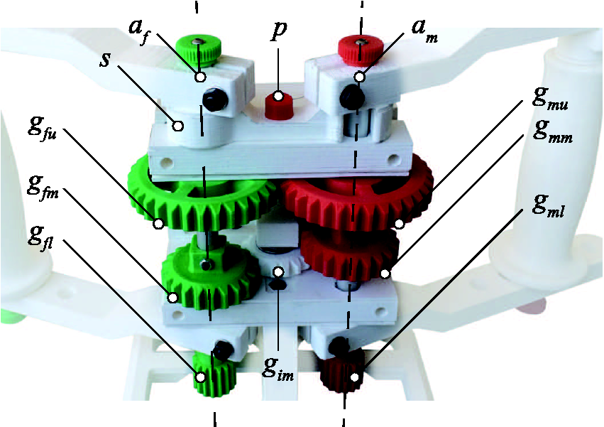
The core mechanism is made up of: a properly supported gearbox, a mode-selection mechanism, and a signal acquisition system. The pivotal component of the device is the mechanism of the gearbox, based on a plastic structure and containing five wheel-gears and three aluminum shafts (10 mm in diameter). Referring to Figure 4, three groups of gears are recognizable: the fixed (hereafter f) group rotating about af and made up of gears gfu, gfm, gfl stationary constrained to an aluminum shaft, the inversion gear gim rotating about ai and the mobile (hereafter m) group rotating about am and made up of gears gmu, gmm, gml. All the gears are mechanically constrained to three aluminum shafts, and secured by steel screws and bolts to avoid free spinning. The gap between gfu and gfm is different from the one existing between gmu and gmm. Shaft am is free to move axially in order to obtain two different configurations of the mechanism and let gears engage differently (Figure 5). Consequently, sliding up and down the m group, two different configurations can be selected: if gfu engages gmu, af and am perform anti-phase rotations; if gfm engages gmm, af and am perform in-phase rotations, thanks to the presence of gim. All the gears in the mechanism are 2 mm in module to guarantee a good mechanical resistance and have a double chamfer in order to ease the engagement of the gears. A selection mechanism s, made up of a 3D-printed lever, is placed above the gears. If it is engaged, it works as a spacer that causes gmu to engage gfu, leading to the anti-phase rotation of af and am. If it is not engaged, gmm is engaged with gfm through gim, leading to an in-phase rotation of shafts. An aluminum pin p (with a 3D-printed cup) locks the position of s for safety. To track the movement performed by the patient, the mechanism is equipped with two potentiometers, measuring af and am rotations through two pairs of gears ( Schematic representation of DUALarm gear mechanism layout in both in-phase and anti-phase configuration.
DUALarm reaching version
In the DUALarm configuration shown in Figure 3, two arms are connected to axis af and am. Each arm is made up of one handle, one aluminum rod (about which the handle is free to rotate) and two links connecting the shaft of the wheel-gears to the handle. Because of the slight sliding movement of am to select the required configuration, every arm includes a spacer that can be placed above or below the handle in order to maintain the left and right handles at the same height. Links are constrained to the shafts of the core mechanism thanks to a friction-based connection tightened by a bolt. In Figure 6 the range of motion (ROM) of DUALarm is described: maximum and minimum angular ranges of the link are reported along with the distance between af and am axes and maximum and minimum distance between the handle and am axis.
Schematic representation of DUALarm range of motion. In the picture the maximum and minimum angles of link rotation together with the more internal and more external positions of the handle along the link are presented.
A complete description of the kinematic model of the device is presented in Appendix 1.
Manufacturing
The device was manufactured thanks to the fused deposition modeling (FDM) technology, an additive manufacturing process consisting in laying tracks of molten thermoplastic polymer onto a platform to obtain a layer of material on the XY plane of the machine (3D-printer). Once the molten layer has solidified, other subsequent layers are deposited in a bottom to top manner, in order to create the complete 3D object in the Z direction of the machine.
All the 3D-printed parts of the device were made by the low-cost FDM 3D-printer Sharebot NG, a machine built following the RepRap layout and, for this reason, very similar for technology, building volume and performances to the wide majority of the low-cost desktop 3D printers commonly found in research labs and FabLabs. The plastic used to build the entire prototype was PLA with a wire diameter of 1.75 mm. Custom parameters for the aforementioned printer have been created and main parameters used are the following: three layers of bottom, three layers of top, 0.2 mm of layer height, four perimeters, 30% “grid” infill percentage, DUALarm manufacturing session with the Sharebot NG FDM 3D-printer. The four PLA perimeters and the 30% “grid” infill percentage are visible.
Even if carefully chosen, some 3D-printing parameters like raster angle, raster width, thickness of layers or air gaps between tracks affect mechanical properties of printed parts.34,35 The bottom-to-top layer structure of the FDM printed components causes the resulting product to be anisotropic for several reasons. Due to this condition, the most common cause of everyday-life mechanical failure for FDM components is delamination between layers originally deposited in the Z direction of the 3D-printer. 34 One of the best ways to avoid delamination between layers is to do a correct design and manufacturing planning, in order to produce a component which will not be stressed in the delamination direction. This approach has been used for almost all the parts of the DUALarm device. Where this condition was not possible, mechanical locks or couplings have been placed, in order to reduce the stress affecting the component on the manufacturing Z direction. As previously stated, all the parts DUALarm is made of are realized in PLA, an easy to print but also very vulnerable to ageing polymer. Different materials with better mechanical properties will be tested in the future inside the DUALarm manufacturing process. Among these higher performance materials ABS, nylon, and carbon reinforced polymers could be tested in order to find a better candidate resulting in more rigid, more durable, and longer-lasting parts.
In order to avoid the typical high friction between two PLA 3D-printed parts, polypropylene components (1.5 mm in height) were positioned onto critical surfaces like the area between upper link (left and right) and upper support plate (left and right), lower link (left and right) and lower support plate (left and right), gears and support plates, handle (left and right) and upper/lower links (left and right). These parts were produced by cutting a sheet of polypropylene obtained by a lamination process, technology which ensures the higher level of smoothness for this kind of material.
Mechanical tests
In order to estimate physical characteristics related to the 3D-printed mechanism of the device, a set of different measuring experiments was done. An experimental setup shown in Figure 8 was laid-out to acquire both data about the static friction and the backlash inside the device.
DUALarm mechanical test bench: a pulley, b adjustable tripod, c load plate, d Dyneema rod, e Optodyne LDS-1000 laser emitter, f Optodyne LDS-1000 acquisition system, g Optodyne LDS-1000 mirror with clamping tool, h DUALarm clamp.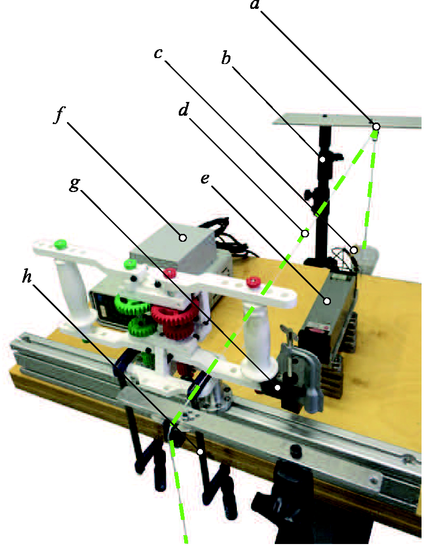
Experimental setup
Here is the setup for both the experiments: DUALarm was secured onto a rigid structure by two clamps. A crushproof Dyneema wire (1 mm in diameter) was secured around the right handle of the device and both the ends of the cable were respectively connected to load plates. The perpendicularity between the wire and the right link of the device was maintained by a system of two adjustable tripods and two pulleys (one for the front side and one for the back side of the device). A Optodyne LDS-1000 contactless acquisition system, made by a laser emitter and a mirror, was used inside the setup. The LDS-1000 mirror was secured onto the lower right link of the DUALarm and the laser emitter was placed in front of it with the axis of the laser beam parallel to the axis of the Dyneema wire.
Static friction
In order to determine the static friction inside the system, the front load plate was loaded as long as the right handle did not move significantly. A significant movement of the link was registered in regard to a force of 5.2 N. Being the distance between the axis of revolution am and the axis where the force was applied (axis of the right handle) 125 mm and the applied force 5.2 N, the resulting static friction torque is 0.65 Nm.
Mechanical backlash
In order to determine the mechanical backlash of the device, several series of complete loading-downloading cycles were done in regard to the front and the back load plates in the same experimental layout previously described. All the measurements were made by the Optodyne LDS-1000 contactless acquisition system and the resulting sets of data were used to extrapolate the force/displacement characteristic presented in Figure 9. The mechanical backlash of the device when gfu engages gmu is visible along the Y axis and is equal to 0.87 mm for the handle positioned at 125 mm from the am axis.
DUALarm force/displacement characteristic when gfu engages gmu. The highlighted segment on the Y axis corresponds to the 0.87 mm backlash of the system in the aforementioned configuration.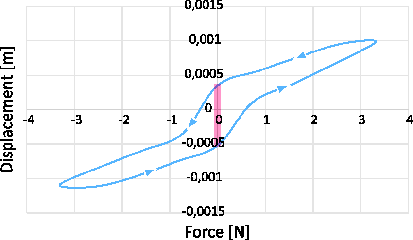
Electronics and software
Even though DUALarm is a completely mechanical device and does not require any additional mechatronical component to perform its rehabilitative tasks, it is equipped with some basic electronical components in order to monitor the activity of patients during rehabilitation sessions.
Two potentiometers (
The high-level PC program is implemented in Python, an easily customizable, open-source and cross-platform language, allowing the program to run on different operating system, even on Linux-based open-source and free distributions, contributing to lower overall use costs of the device. As depicted in Figure 10 the graphical user interface (GUI) of the device is mainly divided into four parts. The first comprises buttons for the initialization of the device, the calibration of angular measures, and a simple editor useful for tridimensional environmental programming. Thanks to this editor the required ROM can be displayed in the second portion of the GUI thanks to an interactive pie chart. Additionally, the colors of the pie chart are related to the ratio between the desired speed for the exercise and the speed achieved by the patient. Finally, the third portion is useful to visually display a real-time updated log of measured angular positions and actual positions of the handles, while the fourth displays the same values in a textual mode. Through customized python scripts it is possible to program exercises, showing to the patient different target points to be reached, tuning the required ROM and target distances according to the actual capabilities of the patient. Reaching time, errors, and other parameters can be constantly logged to have a comprehensive measurement of the exercise.
DUALarm graphic user interface. From left to right: (1) text box to program script-based rehabilitation exercises; (2) tridimensional feedback for the user; (3) real-time graphs; (4) current parameters.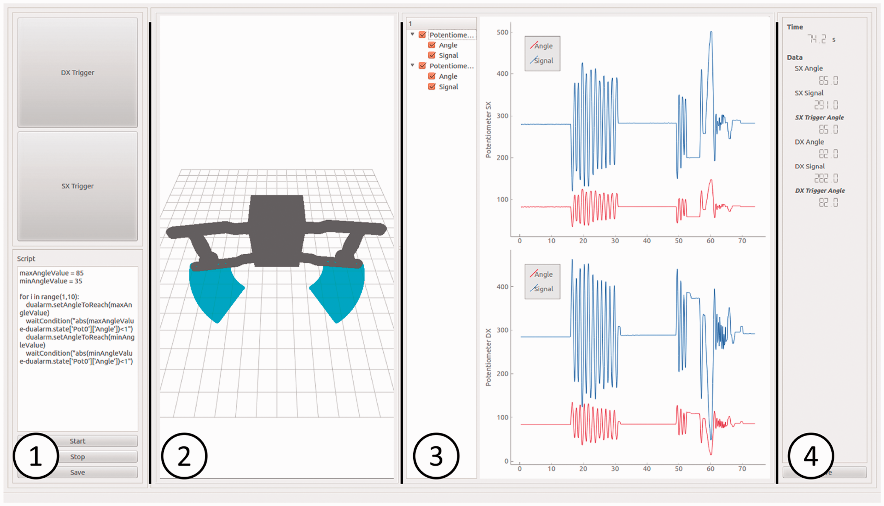
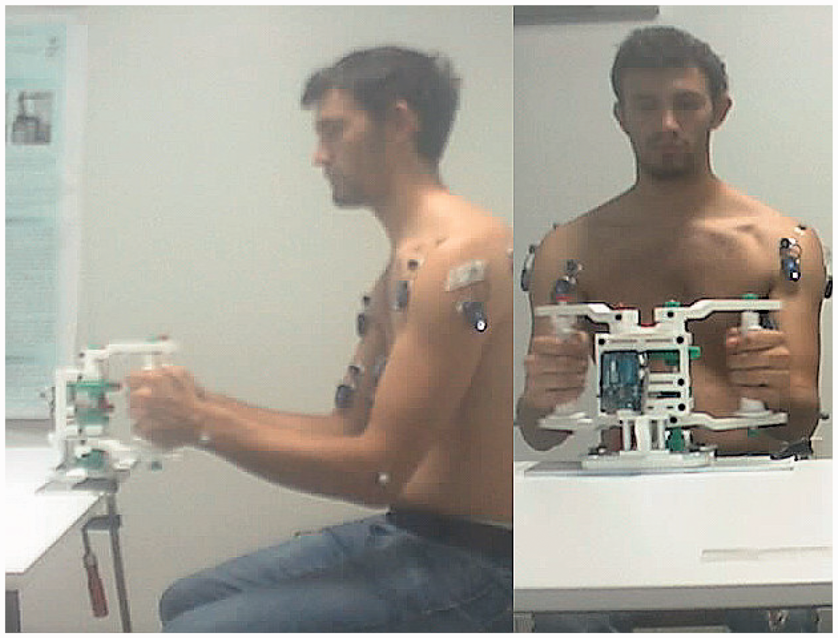
Experimental trials
A preliminary experimental campaign on healthy subjects (Figure 11) was performed. As main general objective, the trials were conceived to investigate physiological interaction with DUALarm in terms of muscular activation patterns. The specific aims were:
defining which representative subset of muscles of both limbs was mainly involved in the planar reaching movement; defining the timing of activation of the above selected muscle to be used as reference for the evaluations on neurological patients; distinguishing muscular activations in different interaction modalities (monolateral, bilateral IP–AP). First experimental trials have been performed with healthy subjects.
Furthermore, DUALarm usability on patients is discussed.
Methods
Study design
Each healthy subject performed preliminary monolateral trials with both right and left limbs, with sEMG recorded on eight muscles (upper trapezius, middle trapezius, pectoralis major, deltoid anterior, deltoid posterior, infraspinatus, biceps brachii, and triceps brachii). A visual inspection of the EMG signals made by an experienced physical therapist allowed the selection of the four more representative muscles involved in the motor task: biceps brachii (BIC), infraspinatus (IS), deltoid anterior (DA), and deltoid posterior (DP). Every subject underwent four different trials, each consisted of 12 cycles (each cycle was composed of a push forward and a pull backwards phase), performed in the following modalities:
In-phase (IP): both the arms work simultaneously during the push forward and pull backwards phases. Anti-phase (AP): the two arms worked in counter-phase. Monolateral (M, right and left): only one arm at a time was involved in the task.
Participants
Five healthy subjects, mean age 34.8 ± 17.7, 4F, 1M, all right-handed, participated in the trials.
Equipment
Surface-EMG activity of the four selected muscles (BIC, IS, DA, DP) was recorded from both arms with the BTS FREEEMG300 system.
Kinematics was acquired with the SMART 3D BTS marker-based optoelectronic system. Eight bony landmarks were recorded: the D5 and C7 vertebra, the right and left acromial process, the right and left lateral homerus epicondiles, and the right and left ulnar styloid. 36
Data analysis
Data were analyzed with in-house developed software. Kinematics was used to detect movement phases. Only the forward phase was considered for analysis. In each trial, mean muscular activations (MMA) of each muscle were computed as follows

Results and discussion
During the execution of the tasks, the device could easily withstand the loads applied by healthy subjects.
MMAs during IP, AS, and M trials are reported in Figure 12.
DUALarm healthy muscular activations. (a) Shoulder intrarotation–extrarotation. (b) Hand (elbow) pronation–supination. (c) Wrist flexion–extension.
DA is the main agonist muscle of the forward phase of the movement, pushing frontally and supporting the weight of the arm. Therefore, analysis and discussion are based mainly on DA activity.
First results indicate that DA activations are higher in monolateral trials than in bilateral ones. Furthermore, in-phase trials show higher activations than anti-phase ones. Activations are symmetrical between the limbs in monolateral and in-phase trials, while anti-phase trials show higher activity in the dominant limb.
In AP trials, DA of the right and left limb fire during the forward phase of the corresponding limb, with a clear predominance of the dominant side on DA agonist action, maybe due to the fact that the dominant limb is usually more specialized in dynamic more demanding tasks. 37
In IP trials, instead, DA of the right and left limb activate equally, and higher than in AP trials. This phenomenon is probably explained by the fact that during AP trials the forward phase of each limb is partially supported by the gravity force of the limb engaged in the coming back phase that pulls in the direction of motion.
Usability trials on patients
Some trials were conducted even on four hemiparetic post-stroke patients with different functional levels to verify whether they were able to use the system and if the core mechanism of the device was able to adapt to non-physiological interactions. Data were not systematically recorded, thus they are not reported. Patients were characterized by different body function, assessed with the Fugl-Meyer Assessment (maximum score = 66; P1 = 40, P2 = 15, P3 = 30, P4 = 48) and physical builds (P1 = 186 cm, 119 kg; P2 = 182 cm, 80 kg; P3 = 162 cm, 63 kg; P4 = 165 cm, 70 kg).
All patients could perform both monolateral and bilateral sessions. Qualitatively, patients took advantage of DUALarm bilateral design in terms of balance, smoothness, and fatigue. Furthermore, the device showed no mechanical yielding or failure.
Safety and certification
Safety for both the patient and the operator is an essential feature for biomedical devices, which is why great importance is attached to product certifications. Three-dimensional printing has given rise to safety and security issues that merit serious concern. 38 Although 3D printing should not be banned, its safety over the long term will clearly need to be monitored. 39
Manufacturing applications of 3D printing have been subjected to patent, industrial design, copyright, and trademark law for decades. 40 However, there is limited experience regarding how these laws should apply to the use of 3D printing by individuals to manufacture items for personal use, nonprofit distribution, or commercial sale. 40
Certification itself becomes a field of technical-legal research that should be adapted to the regulations of each state, but also able to open the doors to a technology with great potential. To satisfy the need for certification, every step of the production process must be standardized in terms of quality and composition. The certification is of great importance to ensure to the end user a standard of quality and production with a security level proportional to the possible risks inherent to any device. Three-dimensional printing is an innovation that captures still unprepared from this point of view. The materials used for printing are well certified (PLA, ABS, nylon, etc.) but today there is no real certification or guidelines referred to print method. 34 A number of fairly simple 3D-printed medical devices have received the FDAs 510(k) approval. 41 However, fulfilling more demanding FDA regulatory requirements could be a hurdle that may impede the availability of 3D-printed medical products on a large scale.42,41
Meanwhile, before considering and certifying the device as fully biomedical, a set of printing parameters are given (sec. manufacturing) and considered unofficially reliable according to authors’ experience as a good compromise among lightness, cheapness, and mechanical reliability. Technical and clinical tests will aim at assessing the proper functioning of DUALarm and await positive outcomes of the DUALarm-based therapy.
Conclusions
The global impact of the DUALarm project is expected to be relevant, thanks to the exploitation of open-source hw/sw more and more available and to low-cost production technologies. This availability is somehow satisfying the continuous and growing request of effective solutions required by the health sector. Positive outcomes from a medical point of view can and must be coupled with the humanitarian relapses, thanks to the possibility of reaching parts of the world in which the use of effective medical devices is precluded due to unsustainable costs.
In order to deeply evaluate the medical effectiveness of the DUALarm-based therapy, it will be required to perform an extensive experimental campaign in order to understand the actual neurological recovery benefits. To understand as widely as possible the use effects of DUALarm a preliminary experimental campaign has recently started, exploiting the use of professional data acquisition systems to monitor both kinematics and electromyographic activity of a set of healthy subjects (sec. experimental trials). Further tests will involve impaired people in order to draw assessed guidelines for the correct use of the device by patients.
As a further study, the DUALarm core mechanism (with pertaining mechanical changes) could be exploited in other low-cost, open-source and 3D-printable rehabilitation devices in order to perform other simple although important movements like shoulder intrarotation–extrarotation, elbow pronation–supination or wrist flexion–extension (Figure 13).
Schematic representation of possible bilateral movements (in-phase and anti-phase) for further studies. In each figure the orientation of the two rotation axes of the DUALarm mechanism is represented in red and green.
From the humanitarian point of view, DUALarm has been developed to be produced and used both in industrialized and in developing countries. The minimum set of elements required to realize the device is: an Internet connection, a 3D-printer, a 3D-printing PLA filament and basic electronic components. DUALarm project aims at having an impact in the health sector without geographical, social, and economic distinction thanks to its low-cost approach and its exploitation process, characterized by a web platform dedicated to biomedical projects which will guarantee the full and wide access to the product and all the related documentation.
Footnotes
Acknowledgments
The authors would like to thank Loris Roveda and Francesco Paolucci for measurement activity, João Carlos Dalberto for supporting prototyping activity, Roberto Bozzi for its electrical wiring, Marta Gandaglia for supporting preliminary clinical trials. Moreover they would like to thank the other members of the Open BioMedical Organization, namely Giancarlo Orsini, Fabio Petronio, Angelo Lenzi and Ferdinando Pisciella, and all the OBM Community for supporting the Initiative. Finally they would like to thank the Sharebot company for everything is related to the 3D-printing world.
Declaration of conflicting interests
The author(s) declared no potential conflicts of interest with respect to the research, authorship, and/or publication of this article.
Funding
The author(s) disclosed receipt of the following financial support for the research, authorship, and/or publication of this article: partially supported by the Italian Lombardy region within the RIPRENDO@home project.
Guarantor
TD
Contributorship
Tito Dinon, Marco Caimmi, Matteo Malosio and Alessio Prini were involved in the design and manufacturing process of DUALarm (mechanics, structure, electrical wiring, software); Alessandro Scano and Andrea Chiavenna performed the data analysis with the help of Marta Gandaglia; Tito Dinon, Loris Roveda and Francesco Paolucci were involved in the campaign of measurement; Joao Carlos Dalberto and Roberto Bozzi supported the team in manufacturing activity; Tito Dinon, Matteo Malosio, Marco Caimmi, Valentino Megale, Cristian Currò and Bruno Lenzi wrote the first draft; all authors contributed to and approved the final version.