
Abstract
Background
The alignment of the lower limb prosthesis is an integral part of the prosthetic fitting. A properly aligned prosthesis contributes to optimal gait and overall function of the patient. The current offering of alignment componentry is expensive for low-income countries. The purpose of this study was to develop a lightweight and low-cost alignment coupler for the lower limb prosthesis.
Methods
An alignment coupler called the reversible adjustable coupling was designed and manufactured. Measurements of total anterior/posterior and medial/lateral and rotation in prostheses were recorded and mechanical testing performed. Swiftness and difficulty of use was also recorded.
Results
The reversible adjustable coupling permitted acceptable ranges of anterior/posterior and medial/lateral translation and 30° of internal and external rotation of prosthetic componentry. Repetitive loading of the coupling at a speed of 1 Hz under 1.28 kN load for 2000 cycles was successful, as were static and strength tests.
Discussion
The coupler provided acceptable ranges of anterior/posterior and medial/lateral and rotation adjustment and is acceptable for potential use in the alignment of both exoskeletal and endoskeletal prosthesis. The final weight of the component was 166 g and cost of $55.00 USD is affordable for low-income countries for use in clinical and educational settings.
Keywords
Background
The alignment of a lower limb prosthesis is a crucial part of the prosthetic fitting and overall patient satisfaction. Quality prosthetic alignment requires years of experience by the prosthetist and a considerable amount of feedback by the amputee. 1 In the field of prosthetics, alignment is the procedure of properly positioning the residual limb, prosthetic socket, and adjoining componentry for optimal performance during ambulation. A prosthesis which is misaligned can be a detriment to prosthesis function and patient performance as well as increase socket pressures and decrease walking speed.2,3 Changing the alignment of the prosthetic foot has been shown to alter knee joint moments, 4 and rotation of components in the sagittal plane has a marked effect on ambulation tactics in transtibial amputees. 5 Alignment of the transfemoral prosthesis is a more involved process for the prosthetist and requires the alignment of a knee joint. 6 Deviations from the optimal transfemoral prosthesis alignment increase lower limb muscle activity and increase oxygen consumption. 4 Observational gait analysis and the combined dynamic alignment can mitigate the aforementioned issues.
In the 1960s the Staros–Gardner alignment coupling was developed to assist with the proper alignment of exoskeletal lower limb prosthetics. 7 Later, Otto Bock introduced the 4R101 Aluminum Sliding Adapter and 4R1 Alignment Jig (Otto Bock Healthcare GmbH, Germany). The 4R101 allowed for sliding of the socket in the frontal and sagittal planes and the 4R1 Alignment Jig offered a simple method of adjusting the alignment while the patient was weight bearing on the device. Another component called the thermoplastic “jacked alignment” device utilized a tilting feature present in the Staros–Gardner component and allowed for independent medial/lateral (ML) and anterior/posterior (AP) adjustment. This device was made from thermoplastic components and was designed to be used with thermoplastic prosthetic shank sections. 8 These alignment devices are especially helpful in academic settings where students are required to statically and dynamically align the prostheses of patient models. For students and novice prosthetists, the dynamic alignment of the prosthesis is an iterative process. These alignment devices assist prosthetists by shortening the alignment process time and are well suited for those who are still developing important alignment skills.
In South East Asia the use of exoskeletal prosthetics is still common and if resources are available, so is the use of an alignment coupling. Prosthetists and students can utilize alignment couplings for exoskeletal and endoskeletal prostheses alignment. However, alignment couplings have high costs and are unable to be utilized in both exoskeletal and endoskeletal designs simultaneously. Developing rehabilitation technologies that are affordable for developing countries has been a noted recommendation from international organizations. 9 This study aimed to develop and assess a low-cost prosthetic coupling for assisting in alignment of the lower limb prosthesis. We sought out to provide a lightweight, affordable, and functional alternative to higher costing components for potential use in clinical and educational settings.
Methods
Design
Designing a coupling that was strong but lightweight was an important requirement of the component. In addition, identifying materials that could be sourced locally and that were affordable was imperative. The first design was made from a polypropylene homopolymer and was lightweight but was unable to achieve optimum durability. 10 Therefore, the decision to use polymethylene (POM) was made, as it is a strong and lightweight engineering plastic that is obtainable in Thailand. The tensile strength of POM is 72 MPa, Young’s modulus is 3500 MPa, and density is 1420 kg/m3. In comparison, aluminum, which is often used in prosthetics, has a tensile strength of 280 MPa, Young’s modulus of 70,000 MPa, and density of 2750 kg/m3. Keeping the overall weight of the prosthesis low is a key prescription criterion of lower extremity prosthetics; POM gives the coupling an advantage in this regard. A finite elemental analysis of an initial iteration of our coupling was performed with some success. These results were published in previous research and provided increased support of utilizing the lightweight POM material. 10
We opted to use this material because of local availability, low cost, and rigid structure. The coupling, which we called the reversible adjustable coupling (RAC), consisted of two 100 mm discs of POM 10 mm thick. A universal center lathe, TOS SUI 40 (TRENS SK, a.s., Trenčín, Slovakia) was used to create holes in all of our discs. In each POM disc, four holes 25 mm in diameter were created and located equidistant from a center hole which was 10 mm in diameter. Along the outer edge of each POM disc were eight small 5 mm holes equidistant from each other. Each disc received a circular cutout below the four ported holes. This cutout was 70 mm in diameter and had a depth of 4 mm. These cutouts were made for the purposes of allowing two sliding stainless steel discs to be sandwiched inside of each of the POM discs. The stainless steel discs are a vital part of the overall strength of the device. A schematic of the RAC device is shown in Figure 1. A stainless steel rod was sourced locally and used for fabrication and in its final connected form the coupling consisted of two POM discs, two stainless steel discs, and alignment pyramids (see Figure 2).
RAC schematic ((1) POM disc, (2) stainless steel disc). POM: polyoxymethylene; RAC: reversible adjustable coupling. RAC. RAC: reversible adjustable coupling.

Mechanical testing
The ISO 2006:10328 is a set of testing procedures that is recognized by the International Society of Prosthetics and Orthotics. These procedures are meant to test prosthetic componentry in static and cyclic testing conditions. The purpose of the static testing is to inflict a maximum load to the device so as to represent the worst possible load on the device. The cyclic testing portion of testing is designed to evaluate the component’s ability to tolerate repeated forces to the component, such as that seen in daily walking. 11 Cyclic testing has been used to evaluate other lower limb prosthetic devices in previous literature. 12 We choose to reference a few of the ISO testing methods for our cyclic testing as it allowed us to fit the RAC to a foot and pylon, a configuration that the coupling is designed to be used in.
To recreate the repeated loading the coupling might experience during dynamic alignment of the lower limb amputee, we utilized a reduced instruction set chip computer to control two servo-pneumatic actuators, Si-Plan Electronics Research Ltd (Stratford-upon-Avon, UK). A 34 mm stainless steel pylon with a bonded female tube adapter was fit into the proximal section of the testing machine. For testing, the proximal end of the RAC received a male pyramid (Otto Bock, Germany) as did the distal end (foot section). A double-ended (Staats) adapter and solid ankle-cushion heel foot (25 cm) was then attached. A foot adapter with a bolt was fastened to the foot and all screws on the pyramids were zeroed and tightened at 15 N m, thread locker was then used on all screws. The proximal pyramid of the RAC was adjusted to 10 mm posteriorly and 10 mm laterally. The distal male pyramid was translated to 10 mm anterior and 10 mm medially from the center of the device. Adjusting the RAC pyramids to its maximum ranges was done to elicit loading of the device at its most extreme and tolerable configuration. The RAC was tested in this single presentation while the machine’s forefoot plate was positioned to 20° and heel plate to 15°, a maximum load of 1.28 kN was applied dynamically at the speed of 1 Hz for 2000 cycles (Figure 3). This setting is not in accordance with standard ISO 10328 testing, which requires cyclic testing of 2,000,000 cycles. However, the machine is designed to cease testing if a deformation in excess of 5 mm occurs. Our rationale for a shortened cycling protocol was related to previous research revealing that lower limb amputees typically take approximately 2000–3000 steps/day,
13
and more recent literature showing an average of 1540 steps/day.
14
Still, a typical dynamic alignment session will range from 1–2 h, requiring the amputee to walk less than they might walk during the course of a single day.
Mechanical testing of the RAC. RAC: reversible adjustable coupling.
Static and strength tests were performed in a universal testing machine (Shimadzu SLFL-100KN, Kyoto, Japan). As alignment is an integral part of testing, we aligned the lever arms to our coupling using the ISO 10328 recommendations, a method used in previous prosthetic testing to apply load forces which are representative of a maximal load at the end of stance phase.
15
A custom apparatus for fixating the proximal and distal portions of our device to the testing machine was created. The total length between the proximal and distal connection points to the loading points of the testing machine needed to be 650 mm. The proximal load point required a vertical offset of 55 mm anterior and 40 mm lateral, the distal load point required an anterior offset of 129 mm and lateral offset of 19 mm. A schematic of our testing apparatus is shown in Figure 4.
Schematic of static and strength testing orientation.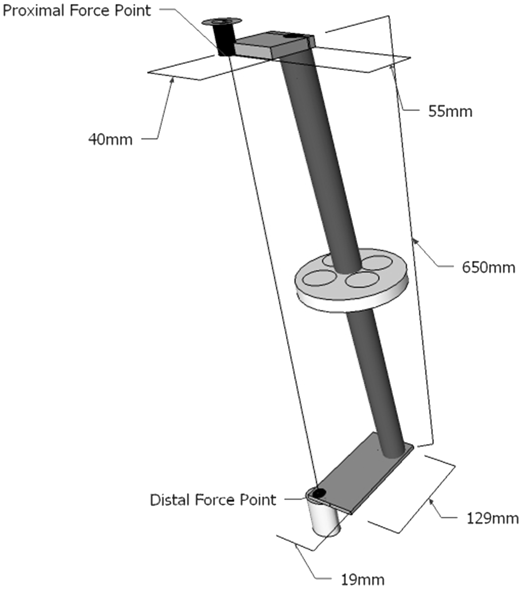
The RAC was attached distally and proximally to pyramids and pylons connected to the testing apparatus. The beginning point for measuring deformation began after a load of 50 N was applied. A static load of 800 N was applied for 30 s at a rate of 120 N/s and then removed. Deformation at load was recorded and upon unloading, permanent deformation was recorded. Two strength tests were also conducted and required a maximum load of 1750 N as well as 3500 N to be applied to the device for 30 s at a rate of 120 N/s and then removed. Deformation at load was recorded and permanent deformation after unloading was recorded. A deformation above 5 mm or fracturing was considered a failure.
Prosthesis testing
The impetus for the creation of the coupling was to provide free ranging adjustment of an actual prosthetic socket and componentry. One certified prosthetist performed all prosthetic testing. The RAC was fit to endoskeletal and exoskeletal transtibial and transfemoral prostheses utilizing common prosthetic componentry. A combination of male and female pyramid adapters as well as exoskeletal wood blocks and screws was used to configure the RAC for testing procedures. One certified prosthetist performed all adjustments in the various endoskeletal and exoskeletal prostheses tested. The AP and ML adjustments of the exoskeletal transfemoral prosthesis were completed using a set of 4 mm hex tools. The anterior and posterior facing screws of the pyramid adapter were loosened and the RAC disconnected splitting the prosthesis into two separate pieces. In order to allow for sliding of the adapter, each screw on the pyramid needed to be slightly unscrewed. We then slid the socket and knee through its full range of motion in both AP and ML directions and measured these ranges with a standard ruler. Subsequently, we performed internal and external rotations of the socket and knee and measured those ranges with a goniometer. The exoskeletal transtibial prosthesis was adjusted similarly by using the 4 mm tools to disconnect the RAC into two pieces and perform the same AP, ML, rotational adjustments, and measurements as conducted with the transfemoral prosthesis. The AP and ML adjustments for the endoskeletal transfemoral and transtibial prostheses were performed using 4 mm hex tools. Translations of the socket and knee or foot sections were then performed to maximum ranges and measured by a ruler. Internal and external rotations were performed and then measured using a goniometer. An image depicting the RAC fit to each type of prosthesis is shown in Figure 5.
RAC fit with lower extremity prostheses. RAC: reversible adjustable coupling.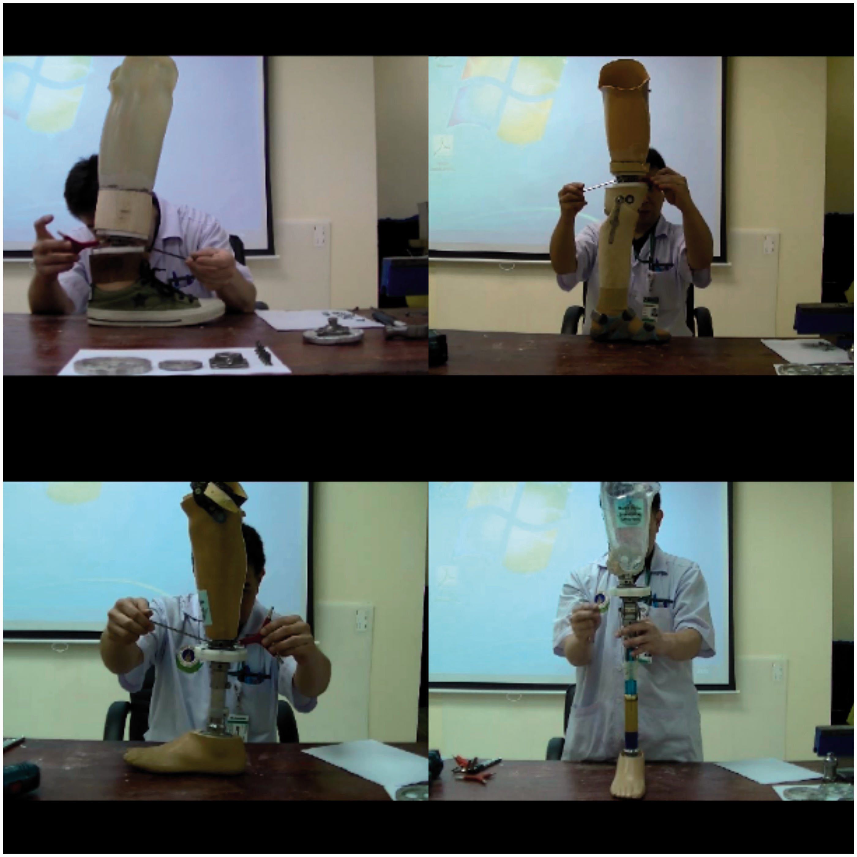
Student testing
Swiftness of use of the RAC as compared to other alignment couplings was performed by a cohort of 21 final year prosthetic students. Each student agreed to participate and signed an informed consent form. Students were timed using a digital stopwatch by a coinvestigator while performing a series of alignment adjustments on separate transtibial prostheses fitted with a RAC, Staros Gardner, Otto Bock 4R101, and Otto Bock 4R1 coupling. The prosthesis socket and foot were placed in 10 mm of medial translation and students were asked to translate socket and foot to a zero translation. Prior to testing the students were provided an hour familiarization period with each of the couplings. A coinvestigator timed students using a digital stopwatch and verified alignment changes with a Vernier caliper. Upon completion of the swiftness of use testing, students provided their opinion through a single scaled question. They were asked: “how difficult (1) or easy (4) was it to use the alignment coupling during the required alignment task?” Students could respond with a choice of; “1 = Very difficult, 2 = Difficult, 3 = Easy, 4 = Very easy.” An average score of the swiftness of use testing and the subjective feedback question was determined for all student participants.
Results
Static and strength mechanical testing of the RAC.

RAC: reversible adjustable coupling.
Characteristics of alignment components.

AP: anterior/posterior; ML: medial/lateral; NA: not applicable.
Attachment of the 4R37 or 4R51 socket adapter allows for full rotation.
Prices are when purchased in Thailand.
Discussion
This initial investigation of the RAC provided an opportunity to examine two necessary characteristics of a prosthetic alignment component, adjustability and durability. The RAC achieved acceptable AP, ML, and rotation translations and withstood successful repeated mechanical loading while fit to a prosthetic foot. Average duration of dynamic alignment for a prosthesis is 1–2 h and the RAC was capable of withstanding loading intended to be representative of a typical dynamic alignment. In addition, static and strength mechanical testing with all three ISO recommended force loads being applied to the RAC was a success. During cyclic testing the loads were directed toward the distal and proximal aspects of the device while the RAC was set in its most extreme orientation, as recommended by ISO. By doing so, the RAC performed well when submitted to shearing that could potentially split the device discs apart. The crux of the device during this situation is its numerous screws which keep the discs of the RAC tightly fastened. For static and strength tests it was important to align the RAC in the universal testing machine in an orientation which could be repeated by other parties and which mimicked an extreme condition. Thus, referring to ISO 10328 was a tremendous help during our study.
Upon completion of dynamic alignment using the RAC, the prosthetist could transfer the alignment of the prosthesis using a variety of techniques commonly used in prosthetic fabrication. Transferring the alignment for a definitive endoskeletal or exoskeletal prosthesis using the RAC is possible by utilization of any widely available alignment transfer jig. The user preserves alignment by placing the prosthesis in the alignment jig and performing standard alignment transferring procedures. Using the RAC for alignment changes of an exoskeletal prosthesis differs from that of traditional wood and glue methods. The traditional method for adjusting alignment requires the prosthetist or technician to cut the wood shank of the prosthesis using a saw, make an alignment shift, and then adhere the pieces back together again. The RAC can be used in an exoskeletal prosthesis and does not require cutting the prosthesis apart, decreasing the amount of time to align a device. Attaching the RAC to the endoskeletal prosthesis might require less fabrication time than when attached to the exoskeletal prosthesis. The exoskeletal adapter requires the separation of the POM discs and their attachment to wood blocks of the prosthesis. However, the ability to use this device simultaneously in both exoskeletal and endoskeletal prosthesis is an added advantage over other alignment couplings. The cost to fabricate and produce the RAC is approximately $55 USD. The lower cost of materials and labor in Thailand made for an affordable means of producing the coupling. Each of the other available prosthetic couplings offers the prosthetist adjustability of the prosthesis but at a far greater price point.
There were a number of limitations to our study. First, our protocol for cyclic testing entailed far less than the number of cycles recommended by ISO 10328. Our rationale for reduced cycles might also be problematic, as an increase in the number of testing cycles could be better representative of the RAC utilized for repeated dynamic alignment procedures as opposed to a single procedure. However, our ultimate strength tests at high loading forces proved successful. Future research could help better understand the effects of an increased number of cycles during cyclic testing. Continued long-term use research is currently being performed in real clinical situations. Long-term follow-up outcomes covering durability, usability, utility, and user feedback will provide important outcome measures. Our RAC has a limitation in its design which necessitates the separation of either the socket or shank section of the device in order to translate or rotate the pyramids on the RAC. This could add additional time to the alignment process altogether. Additionally, using the RAC in an exoskeletal prosthesis necessitates use of a longer wrench to adjust the pyramid for angular adjustments. Translation of these pyramids typically necessitates backing out two pyramid set screws to detach the socket or distal shank of the prosthesis. However, angular adjustments of the prosthesis are still permissible by adjustment of pyramid set screws. Finally, the exoskeletal setup of the RAC was not put through mechanical testing. If possible, exoskeletal mechanical testing could be conducted to give a better indication of repeated loading of the device in this type of prosthesis. We sought out to design and develop an affordable, durable, and functional alignment tool for the lower limb prosthesis. Our decision to keep production and fabrication local granted us affordability. Alignment components are often times used in prosthetic education and training programs. The RAC could offer students and practitioners an affordable and widely adjustable alignment tool for developing alignment skills and providing dynamic alignment of the prosthesis.
Key points
A lightweight and durable prosthesis alignment component was developed Internal and external rotation as well as AP/ML movements were permissible Local fabrication allowed for a low cost of $55.00 USD Students and prosthetists could use the RAC to hone dynamic alignment skills.
Footnotes
Acknowledgments
We would like to thank all administrative and technical staff who assisted us throughout the project development, including Mr Pornchai Puengjaroen for his valuable technical assistance.
Declaration of conflicting interests
The author(s) declared no potential conflicts of interest with respect to the research, authorship, and/or publication of this article.
Funding
The author(s) received no financial support for the research, authorship, and/or publication of this article.