
Abstract
The two-step production process of glass-ceramic dental restorations involves a computer-aided design/computer-aided machining step followed by a crystallization firing for the final material properties to be achieved. Certain firing parameters are believed to trigger spontaneous fracture of crowns during the cooling process. In this study, cooling fractures have been reproducibly observed and investigated using fractography combined with material (glass transition temperature) and process (cooling rate) characterization. Stress distribution was visualized using birefringence measurements. Fractographic observations revealed fracture starting at the intaglio side of the crowns specifically at contact points with the support firing pins. Further analysis showed that a fast cooling rate was applied during the glass transition region. Thermal stresses were concentrated around the firing pin supports and released the fracture. To prevent such fractures, a slow cooling protocol below the glass transition temperature is our recommendation to dental technicians. Furthermore, the use of planar firing pad or paste supports is advised over the use of point contact supports.
Keywords
Introduction
Computer-aided design (CAD) followed by computer-aided manufacturing (CAM) technologies entered the dental field already more than two decades ago. Meanwhile, the designing precision, as well as the finishing quality, reached a level of clinical acceptability. Alongside with this progress in subtractive manufacturing, the dental industry developed a series of tooth colored materials for single and even multispan dental prosthetic restorations. The material portfolio thereby spans over a broad range from pre-polymerized composite blocks up to high-strength pre-sintered or fully sintered ceramic materials.1–3 Partly crystallized glass-ceramic materials (e.g. reinforced with leucite or lithium silicate crystallites) exhibit the great advantage of very well tooth adapted esthetic appearance combined with sufficient strength for single-unit restorations, namely full-contour crowns. In order to provide the mechanical stability against the chewing or even unphysiological loading in the dentition, only highly crystalline ceramics have proven to show a clinical stable performance against fracture. 2 , 3 Such high crystalline content is best approached via glass-ceramic processing out of lithium silicate–based glass precursors. Following to a two-step thermal procedure, consisting of nucleation and crystal growth, crystal content of above 50 wt% is usually achieved.
The actual delivery of such block materials to dental technicians depends on the respective manufacturer strategy. While some offer one-step materials already fully crystallized, others market two-step pre-crystallized materials which have to be finally crystallized only after CAM processing. The advantage of the one-step procedure is surely found in economical reasons while two-step materials present a stronger version due to a proposed “surface healing” of defects during the thermal crystallization treatment. In any of the described versions, a final tempering, glazing, or healing firing is optionally recommended to enhance the mechanical strength. 4
Glass-ceramics on the basis of lithia (Li2O) and silica (SiO2) are smart and thus preferred materials in this context due to a two-step crystallization procedure. While only lithium metasilicate (Li2SiO3) is the predominant crystallite phase in the pre-sintered stage, lithium disilicate (Li2Si2O5) takes over after final crystallization. This has the advantage of easy machining of the smaller and less percentage of crystallites and greater strength of the finally sintered lithium disilicate crystallites. 1
The crystallization firing procedure of a machined dental restoration involves a heating range, a holding period at crystallization temperature (e.g. 8 min at 840°C), followed by subsequent cooling down to room temperature. The cooling rate from crystallization temperature has been shown previously in related subjects to influence the build-up of internal stresses at different microstructural levels. The most known fact in dental technology is the beneficial effect of a slow cooling (SC) procedure on the chipping prevalence of ceramic veneered zirconia restorations. 5 , 6 With typical dental sintering ovens, the cooling rate can only be controlled by a guided opening schedule of the oven chamber.
In dentistry, the single-tooth replacement using ceramic materials is best achieved with lithium disilicate glass-ceramic materials which exhibit a long-term clinical stability and good success rates. 7 This however is not yet established and clinically proven for more recent lithium silicate based glass-ceramic materials. In recent studies, we observed several early and unexpected fractures of dental lithium silicate glass-ceramic crowns during the final crystallization procedure, precisely during the cooling phase. A specific type of bulk fracture became reproducibly observable within a certain temperature range. Our aim with this report was to fractographically analyze four fractured crowns, analyze the reasons for failure, and to identify ways to prevent those aggravating fractures.
Materials and methods
The case reports presented here are part of a broader study on processing of lithium silicate crowns, investigating the influence of firing pins versus firing pastes or firing wool and the investigating the influence of the cooling protocol from crystallization temperature. 8 Molar crowns (n = 8 per group) were fabricated from the pre-crystallized lithium silicate material Vita Suprinity PC (Vita Zahnfabrik, Bad Säckingen, Germany) in a high translucent shade (0M1-HT, LOT: 63321). The crowns were manufactured using a standard geometry (*.stl- CAD interface) representing the typical morphology of a second molar tooth (Figure 1(a)). The crowns were manufactured in the Sirona inLab MXCL CAD/CAM machine (Dentsply Sirona, Bensheim, Germany) using the inLab CAM 15.2 software (Dentsply Sirona) and a standard set of burs (Step Bur 12s, Pointed Bur 12s). The crowns were either placed on different firing pins (platinum, silicon nitride, cordierite) or planar supports (fibrous pad, firing paste). The fractures under investigation (n = 4) were retrieved from a cordierite firing pin (Vita Zahnfabrik, Figure 1(b)). Crowns were finally crystallized in a bottom-up lift furnace (Vacumat 4000 Premium T, Vita Zahnfabrik) typically used for sintering of dental prostheses (Figure 1(c)). The crystallization protocol required a holding time of 8 min at 840°C under vacuum with SC until 680°C. The cooling rate was controlled by a closed furnace chamber and bottom opening at 680°C. We reproducibly observed the formation of bulk fractures of the crowns (all crowns fractured during cooling) during opening the furnace chamber at elevated temperatures (Figure 1(c); the actual event can be viewed at https://youtu.be/51DwjGd88aI).

Lithium silicate material used for crown production (a), crowns on the firing pin (b), crystallization furnace with bottom-up lift system (c), and fractured crown after crystallization (d).
Case section
Four fractured crowns were analyzed fractographically in order to identify the fracture origins. The crown fragments were photographed with standardized illumination and equipment (Nikon D100, Medical-Nikkor 120 mm, Nikon) and observed under a stereomicroscope (SV6, Zeiss) using lateral illumination. The fractured crowns were then gold sputtered for examination under a scanning electron microscope (SEM, Leitz ISI SR 50, Akashi, Japan). The fractographic examination was conducted using a systematic approach 9 and interpretations of the fracture patterns were based on established methods. Arrest lines, hackle, wake hackle, compression curls, or any other characteristic features were identified in order to trace back crack origins, propagation direction, and discriminatory indicators of crack initiation/acceleration mechanisms. The fractographic analysis is shown in Figures 2–5.

Stereo light (a) and scanning electron (b) microscopy of the fractured crown #1. The compression curl is observable as well as the opposite fracture origin (bottom arrows in (a) and (b)). The stereo microscopic image further highlights remnants from the supporting pin. Small hackle lines indicate the direction of crack propagation (arrows, dcp) in (b).

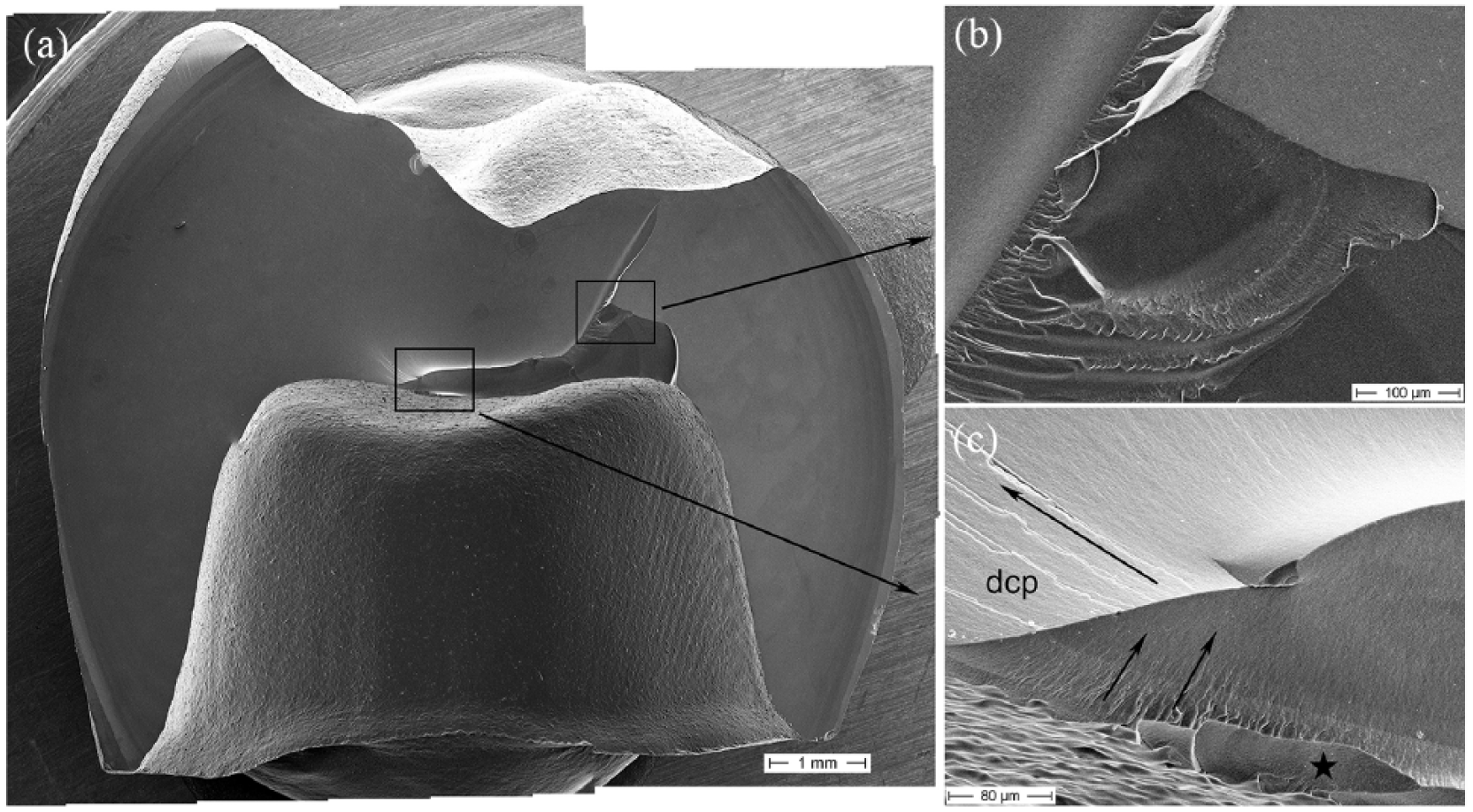
A stereo light microscopic view inside the crown lumen of crown #2 indicated the color changes at the contact points with the firing pin (a). The crack propagated—most likely emanated—exactly at this contact point (arrow in (a)). The SEM view of the fractured crown #2 located the fracture origin at the intaglio side of the crown ((b); arrows indicate the dcp). (c) A reaction zone at the contact point with the supporting pin (arrow).
SEM overview showing the entire fracture plane of crown #3 (a). A closer magnification in (b) reveals the location of the fracture origin. Surface flaking is indicated by the asterisk as well as fine hackle lines trace back the dcp toward the fracture origin (arrows). (c) A secondary, internal fracture event. The smooth facture planes combined with sharp twisted fracture planes indicate the formation of locally steep stress gradients during cooling from crystallization temperature.

SEM view of an internal fracture origin on crown #4 (a) shows gap opening after crystallization. A close-up magnification (b) further shows crack formation in the vicinity of the fracture origin, only visible after light HF etching (0.5% HF etching was applied in order to investigate potential anisotropy/texturization of the crystalline microstructure upon cooling. Based on the SEM analysis of this crown, no such effect was observed).
Glass transition temperature
Of special interest was the thermodynamic material response upon cooling. The transition from a viscous state into the elastic solid state, typically characterized by the glass transition temperature Tg, was measured using thermomechanical analysis (TMA). However, as the material changes its microstructure during crystallization, the Tg of the crystallized material was in focus. The TMA measurements were carried out in a TMA 402 Hyperion (Netzsch Gerätebau, Selb, Germany) in penetration mode by heating up crystallized samples of 200 µm thickness using an indentation load of 0.1 N (Figure 6). The Tg was identified at 634°C/639°C which did not differ from the pre-crystallized version (636°C) regardless of the different microstructures.

Thermomechanical analysis of the pre-crystallized lithium silicate material (black line) and the crystallized version (red and blue lines). Glass transition temperatures were located at 634°C, 636°C, and 639°C.
Oven temperature
The furnace was controlled by its internal temperature management and opened automatically at 680°C. In order to investigate the real cooling rate exactly at the crown site, as well as the cooling rate inside the crown, temperature profiles were recorded used a N-type thermocouple (Omega Engineering UK). Figure 7 shows the cooling profiles for furnace opening straight after holding time at 840°C (FC, fast cooling), at 680°C (REF, reference cooling as per manufacturer IFU), or opening only at 550°C (SC).

Temperature profiles, measured during opening of the furnace stage: fast cooling (FC; opening at 840°C) versus reference cooling (REF; opening at 680°C) and slow cooling (SC; opening at 550°C). The straight lines represent the temperature profile in the furnace chamber, the dashed lines represent the temperature inside the crown lumen during opening, and the dotted lines show free cooling at the exact location of a crown.
Birefringence measurement
The occurrence, distribution, and magnitude of residual stresses locked within the crown under investigation can ideally be investigated by means of light birefringence. 6 , 11 By determining the phase delay of the two component waves of polarized light passing through a translucent structure, the magnitude of residual stresses (σres) in the material can be determined. To this effect, the thickness of the sample (t) and the coefficient of photoelasticity (Cel) of the material, which relates the light retardation to the difference between the two principal stress vectors, 12 have to be known. As the specimen preparation for light birefringence measurements presents a semi-destructive approach, σres has to be discussed with caution, as a major part of stress is most likely released due to specimen slicing.
Two non-fractured crowns according to the above crystallization process were sectioned using a low speed saw and a 0.3-mm-thick diamond blade (IsoMet, Buehler, USA) under constant water irrigation and following two orientations: sagittal or transversal to the crown main axis. Six sagittal slices, with an average thickness of 1.00 ± 0.1 mm, were obtained from one crown (Figure 8(a)), whereas the thickness of the four transversal slices was fitted to preserve the firing pin support area in the inner side of the crown (Figure 8(b)). Their thickness ranged, therefore, from 1.2 ± 0.1 mm for the cervical slice to 1.75 ± 0.1 mm for the mid-coronal slice. As the focus of interest was directed to the fracture plane and the contact with the firing support, those slices have primarily been analyzed. For comparisons, the same cuts were taken from a group crystallized on alumina fibrous firing pads, avoiding the point contact induced by the supporting pin.

Preparation of crown slices for birefringence analyses: (a) sagittal cuts and (b) transversal cuts. The qualitative mapping of the stress distribution is shown for (c) a pin supported crystallization protocol versus (d) a firing pad supported crystallization protocol. (c) The concentration of stresses close to the contact with the firing pin in both the sagittal and transversal cut. (d) in contrast represents a virtually stress-free microstructure. The nature of the stresses is indicated by the white dashed lines in the magnification of the sagittal cuts. The concentric orientation around the supporting pin (c) is in contrast with the homogeneous alignment in (d). The magnitude of the stresses was color-coded between 0 and 1.6 MPa.
Stress birefringence measurements were carried out in an automatic polarimeter (StrainMatic M4/120.33, ilis GmbH, Germany) with spatial resolution of 11 µm/px. Sagittal and transversal slices were measured individually and their position toward the machine was kept constant in order to facilitate subsequent comparison. The light retardation (δ) was determined using the rotation angle (α) according to

where λ is the wavelength of the light source (593 nm). Residual stresses (σres) were then calculated for each sample using the measured Cel of the material and the respective thickness (t) of the slice

Obtained data were analyzed with the software StrainAnalyzer (v. 2015.190, ilis GmbH) and the results exported as suitable image files. The Cel was calculated based on the correlation between the applied diametral tensile stress on a stress-free disk (n = 3) and normalized optical light retardation. The Cel was averaged to 8.09 (±0.05) 1/TPa for the material under investigation.
All birefringence measurements were carried out at controlled conditions at 23°C and 30% rel. humidity.
Results and discussion
The fractographic examination revealed a fracture type emanating during cooling from crystallization temperature. Figures 2–5 show the fractographic patterns on the fracture planes of four different crowns, all fractured during cooling. All evidence pointed to a contact issue with the supporting pin. Figure 2 shows the fracture origin at the contact site with some minor flaking and discoloration at the contact site. The direction of crack propagation is indicated starting at the intaglio side and terminating at the outer surfaces of the crown (compression curl). Figure 3 further shows a reaction zone around the discolored contact with the supporting pin. It can only be hypothesized at this point, that the pin material—cordierite (Mg2Al3[AlSi5O18])—is of a silica-based chemical composition (cyclosilicate) and would certainly dissolve and fuse to a certain amount with the lithium silicate crown material upon contact at elevated temperatures. Furthermore, as the coefficient of thermal expansion (CTE) of the glass-ceramic crown material (suprinity: 12.3 × 10⁻⁶ 1/K (manufacturer data)) and the support pin material (cordierite: 0.1 × 10⁻⁶ 1/K (Kyocera web database)) highly deviate, stresses would occur at fused contacts upon cooling. It has to be mentioned that also silicon nitride exhibits a thermal mismatch with the crown surface (CTE (Si3N4): 2.4–3.5 × 10⁻⁶ 1/K (Kyocera web database)), but apparently less deleterious, as this investigation did not show crown failures on silicon nitride pins. A high CTE mismatch could trigger minor edge fractures of the porous support pin which stay fused to the crown surface, as can be seen in Figure 3(a). Figure 4 shows another example of a fracture origin located close to the contact point. Surface flaking was observable too. Figure 5 exhibits an internal fracture origin, however close to the intaglio contact point. The magnification clearly shows gap formation which is a strong indicator of steep thermal gradients and kinetically delayed material contraction upon cooling.
In the literature, this type of failure origin is termed “chill check” 13 and represents a failure emanating during sudden chilling of a hot specimen. A great temperature gradient from the already cooled surface to the still heated bulk of the specimen accounts for that failure type. In brief, a surface cooled below the glass transition temperature behaves elastically (no viscoelastic flow) while the bulk of the material still compensates the cooling contraction by viscous flow. Upon further cooling, the internal region will shrink and give rise to elastic tensile strains, radially oriented toward the specimen surface. This effect is reported to be amplified in restorations of varying or increasing thickness. 14 As fracture origins are commonly located at regions of high tensile stresses, this type of chill check fracture origins might be located subsurface or even deep in the bulk of a material. 10 As the cooling of the crowns was not overlaid by external mechanical loads, the main cause for failure was due to thermal stresses upon cooling. Tholey et al. 6 measured thermal gradients in dental constructs during cooling and found steep temperature gradients comparing the inner and outer restoration surfaces. SC thereby lead to a minor temperature difference compared to FC and is thus recommended as the preferred practical procedure. 6 , 14 For further examination of thermal stress, two parameters are of interest: the glass transition temperature of the crown material and the temperature profile for cooling those crowns.
The glass transition temperature was determined at 636°C using TMA in penetration mode (Figure 6). This makes clear that a transition from the viscous to the elastic state happens only after opening the furnace chamber at 680°C. The cooling rates at different locations on the firing stage are shown in Figure 7. The cooling rate in the closed furnace is calculated to 37.2°C/min. However, it becomes obvious that the internal furnace temperature control is not representative for the cooling rate after opening and at the actual crown site. Upon bottom opening, the furnace reading already shows a cooling rate of 62.2°C/min, but the actual crowns become suddenly exposed to ambient temperature and cooling rates of 104.6°C/min were measured. This FC unfortunately starts above the glass transition temperature. Based on visual examination during furnace opening, the cracks rapidly formed in a temperature range between 600°C and 400°C.
As the support firing pin left an impression at the crown contact (as already confirmed by fractography; Figure 3) and as this region released the fracture, the main cause was supposed due to the formation of internal stresses upon rapid cooling. Birefringence measurements present an ideal tool visualizing stress patterns in thin translucent specimen slices. The respective third sagittal and transversal cuts (Figure 8(a) and (b)) show the increased stress magnitude in the contact area of the firing pin. The stress color scale was set here between 0 and 1.6 MPa in order to highlight the distribution of the residual stresses in the form of concentric residual stresses around the support area (Figure 8(c)).
The nature of the stresses (dashed white lines in Figure 8(c) and (d)) was compared to a reference crystallization firing where the crown was supported on a fibrous pad (Figure 8(d)). Although it is not possible to determine whether the stresses are tensile or compressive, their concentric orientation around the support point in Figure 8(c) contrasts with the homogeneous alignment in Figure 8(d). The absolute magnitude of stress was color-coded between 0 and 1.6 MPa but this value might be a rough estimate as a substantial increment of residual stress is released upon cutting. The build-up of stresses, however, developed as a consequence of the support pin, led to the occurrence of sagittally oriented thermal cracks in the crowns under investigation.
The REF cooling protocol in Figure 6 was compared to FC (furnace opening at 840°C) as well as SC procedures (furnace opening only at 550°C). Although the cooling rates might not differ significantly, the SC procedure presents a more protective alternative as the crowns stay at reduced cooling rates (20°C/s) in the range of the glass transition temperature (636°C) and only fast cool after 550°C with the consequence of reduced internal stress build-up. A study on cohesive failure of all-ceramic crowns showed an improved mechanical resistance to fracture upon retarded cooling through the glass transition region and recommended a SC firing protocol. 15 For practical reasons, the SC protocol should be recommended for dental technicians. Furthermore, the use of planar firing pad or paste supports is advised over the use of point contact supports.
Conclusion
The crystallization firing of lithium silicate glass-ceramic dental crowns has led to spontaneous fracture during cooling from the crystallization temperature. This effect was observed at high cooling rates combined with supporting the crown on a firing pin. FC in the range of the glass transition temperature led to internal stress build-up, further concentrated at the contact points with the firing support pins and resulting in restoration fracture. To prevent such fractures, a SC protocol below the glass transition temperature is our recommendation to dental technicians. Furthermore, the use of planar firing pad or paste supports is advised over the use of point contact supports.
Footnotes
Acknowledgements
The authors thank the Vita Zahnfabrik for kindly providing the test materials and for CAD/CAM manufacturing the pre-crystallized crowns. The authors especially appreciate the continuous support and scientific discussions with Michael Gödiker and Dr Armin Kirsten through the project.
Declaration of conflicting interests
The author(s) declared no potential conflicts of interest with respect to the research, authorship, and/or publication of this article.
Funding
The author(s) received no financial support for the research, authorship, and/or publication of this article.
Informed consent
Informed consent for patient information to be published in this article was not obtained because no human subjects, no patients, or no human tissue (e.g. extracted teeth) were part in the study. All reported cases were of experimental nature and investigated in a pre-clinical state.