
Abstract
Objectives
Stent implantation for the treatment of aortic coarctation has become a standard approach for the management of older children and adults. Criteria for optimal stent design and construction remain undefined. This study used computational modelling to compare the performance of two generations of the Cheatham-Platinum stent (NuMED, Hopkinton, NY, USA) deployed in aortic coarctation using finite element analysis.
Design
Three-dimensional models of both stents, reverse engineered from microCT scans, were implanted in the aortic model of one representative patient. They were virtually expanded in the vessel with a 16 mm balloon and a pressure of 2 atm.
Results
The conventional stent foreshortened to 96.5% of its initial length, whereas the new stent to 99.2% of its initial length. Diameters in 15 slices across the conventional stent were 11.6–15 mm (median 14.2 mm) and slightly higher across the new stent: 10.7–15.3 mm (median 14.5 mm) (p= 0.021). Apposition to the vessel wall was similar: conventional stent 31.1% and new stent 28.6% of total stent area.
Conclusions
The new design Cheatham-Platinum stent showed similar deployment results compared to the conventional design. The new stent design showed slightly higher expansion, using the same delivery balloon. Patient-specific computational models can be used for virtual implantation of new aortic stents and promise to inform subsequent in vivo trials.
Keywords
Introduction
Stent implantation for the treatment of (re-)coarctation of the aorta (CoA) has become a standard approach for the management of older children and adults. Although the indications and methods have been well discussed, the criteria for optimal stent design and construction remain undefined. Most stents used for the CoA treatment were designed for other uses. We used computational modelling of CoA stenting in the design process of a modified version of the Cheatham-Platinum (CP) stent (NuMED, Hopkinton, NY, USA).
A modified CP stent was manufactured with the aim to improve foreshortening when deployed at higher diameters. Before clinical testing, we wished to ensure the modifications made to the stent were not detrimental to its behaviour over the normal operating range.
Patient-specific modelling with a conventional CP stent has been described for a patient who then underwent CoA stenting. 1 Deployment of known stents has been simulated for coronary bifurcations. 2 The aim of our study was to assess deployment of a conventional versus a modified CP stent by biomechanical simulation in a virtual CoA environment prior to clinical testing.
Methods
Stent properties
The standard CP stent has a closed cell design and is formed of gold welded rows of bent platinum-iridium alloy wires. Eight bends are made in each crown to achieve a compromise of expansion potential with minimal deployment profile. This allows a large maximal diameter (22 mm) and good radial strength, but also foreshortening at higher diameters and increased fracture risk when subjected to significant repetitive mechanical stress. 3 The closed cell design causes foreshortening of up to 40% at the top end of the expansion range. The new CP stent is a prototype with the same material properties, but with a new configuration designed to limit shortening behaviour. Micro-computed tomographies (CTs) of the conventional and the modified CP stents were obtained for modelling. The same material property assumptions were made for both stents, neglecting the welding material with its small volume and lower stiffness.
Aortic model
A preinterventional CT was performed per clinical indication on GE Lightspeed Volume CT, slice thickness 0.625 mm, prospectively acquired in mid-diastole. The relevant ethics committee waived informed consent for further use of the images. This was a proof of concept study using a patient-based rather than an artificial virtual environment, without interventions in humans. Only one set of patient data was used to create the virtual environment for stent testing at this time, analogous to conventional bench testing of new stent designs in one artificial virtual environment. Patient data were chosen based on the following criteria: adult, aortic coarctation in the typical location just distal to the left subclavian artery origin and good quality CT scan. DICOM data from the aortic and stent CTs were imported into the virtual environment. The distal end of the aortic model was chosen to be approximately 5 cm below the prospective distal end of the stent to ensure that boundary conditions did not influence implantation.
Simulation of stent delivery
First, plastic deformations were induced in the bends of each stent by expanding it with a rigid cylinder to 33 mm (nominal diameter x2). Next, the stent was crimped on a 50 mm balloon to a diameter of 3.1 mm (see Figure 1).
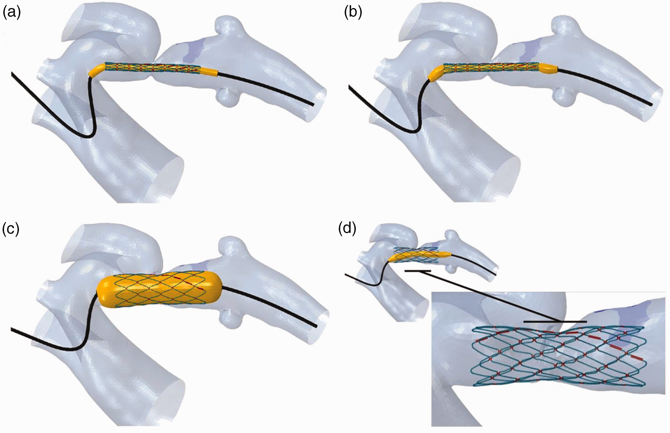
Stent deployment into the aortic isthmus in the virtual environment. (a) A guidewire with the stent crimped on a balloon, placed over an approximate aortic centreline; (b) the guidewire is relaxed inside the vessel to obtain a natural configuration of the delivery system; (c) balloon inflation; (d) the final configuration of the stent.
The compliance chart of a BIB balloon (NuMED, Hopkinton, NY, USA) was used for balloon model calibration, considering only the outer, 16 mm balloon which influences the final, expanded shape of the stent.
The delivery system was then overlaid within the aortic model, with the centre of the stent at the site of the most severe stenosis. A guidewire modelled with the properties of a stiff polymer was bent over the approximate centre line of the aorta. The guidewire was then relaxed inside the vessel to obtain a natural configuration of the delivery system, and to take into account the forces and deformations induced by the delivery system on the aorta prior to balloon expansion.
Finally, the virtual balloon was fully inflated with a pressure of 2 atm, as had been done in the clinical procedure.
Measurements
Foreshortening was measured as the post-implantation stent length as a percentage of the initial stent length.
The proportion of apposed (<0.5 mm between outer strut surface and inner aortic surface) surface area was measured for each stent, ignoring the thin gold layer.
Stent diameters in 15 equally distributed slices were calculated as the twofold mean radius between the calculated centre of the cross-sectional area and the struts. A Wilcoxon signed-rank test was applied to examine for differences in the resulting stent diameters. Figure 2 shows the cross-sectional slices in the virtual model and a reconstruction of the post-implantation CT.

Cross-sectional slices in the virtual model (left) and a reconstruction of the post-implantation CT (right).
An elastoplastic material was used for calibration of vessel properties. Arterial maximum principal logarithmic strain was measured and overlaid as colour maps on the aortic model.
Results
The conventional stent foreshortened from 43.5 to 42.0 mm (96.5%) and was apposed over 31.1% of its outer area. The new stent foreshortened from 51.4 to 50.9 mm (99.2%), and apposition covered 28.6% of its area.
While malapposition of the stent in the stenotic area would have been undesirable, both stents were malapposed at the left subclavian artery origin (old stent: S2-S6, new stent: S3-S6), which may positively affect flow into that artery.
Table 1 shows the post-implantation diameters of both stents. Diameters in 15 slices across the conventional stent were 11.6–15.0 mm (median 14.2 mm) and slightly higher across the new stent: 10.7–15.3 mm (median 14.5 mm) (p = <0.05).
Diameters of the conventional and the modified stent at full inflation at regular intervals along the length of each stent.

Both stents led to deformation of the aortic wall only in the areas of good apposition and the immediately adjacent areas (i.e. the caudal aspect of the proximal left subclavian artery), which is the desired effect of the intervention to increase the vessel diameter at the stenosis (Figure 3).
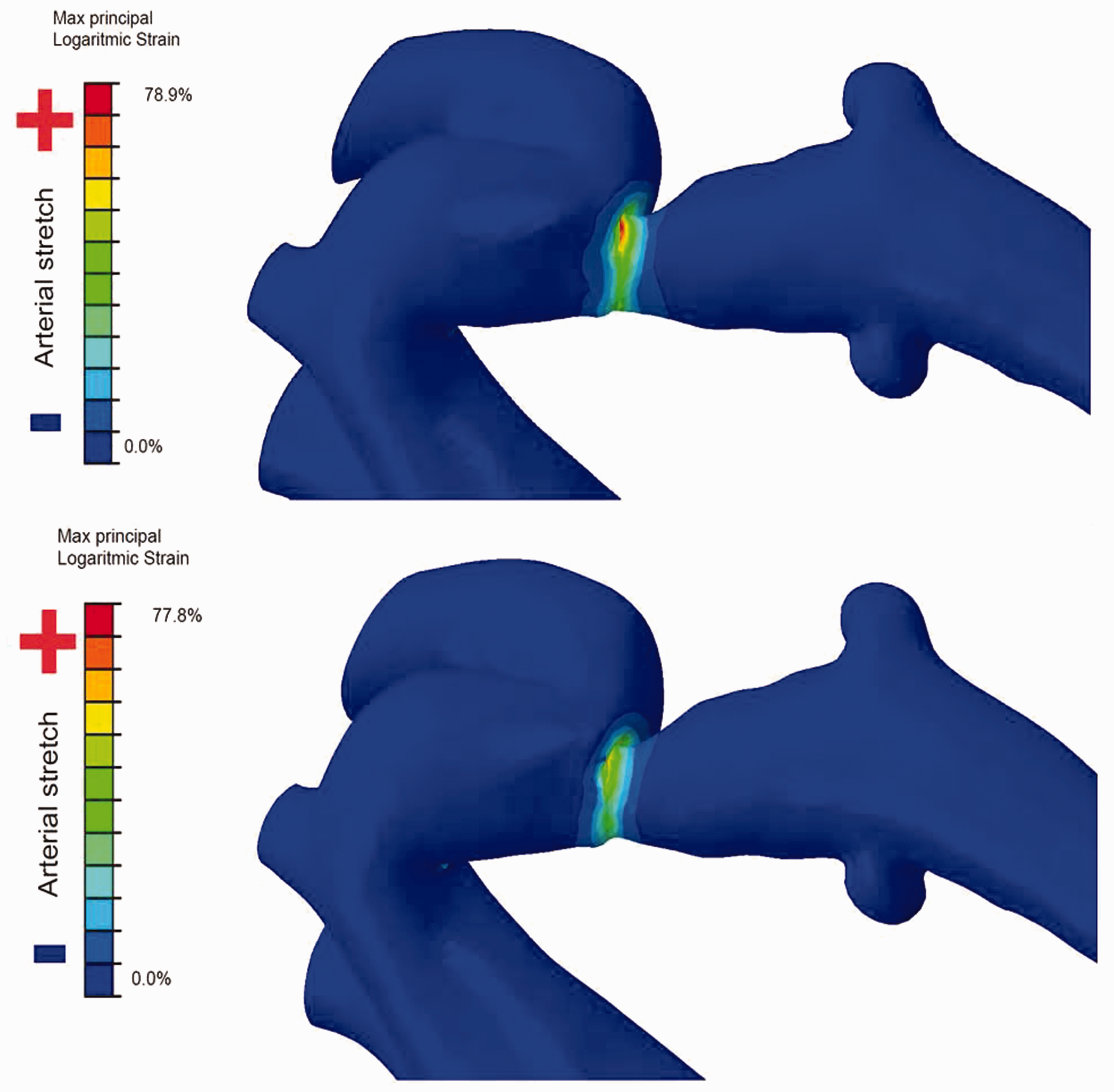
Aortic wall strain in the same area by the conventional (top) and the new stent (bottom).
Discussion
To our knowledge, this is the first description of a patient-specific computational model to examine the properties of two different stents during implantation and their effects on the vessel wall. The standard method for virtual bench testing involves an idealised geometrical model of the target vessel. 4 However, with the availability of high-resolution three-dimensional cardiovascular imaging, models can be made to mirror real-life anatomy.
The conventional CP stent is widely used, and this modelling method was chosen for a preliminary evaluation of a stent modification. The key objective was to ensure that the modifications did not adversely affect the expansion and foreshortening behaviour or aortic wall strain.
Arterial strain is an important immediate stent implantation endpoint, determining the resultant diameter of the stenosis after treatment, and can be measured by finite element analysis. 5 Both stents resulted in similarly high aortic wall strain. Future virtual trials should include testing on known weak spots in the vessel wall (e.g. stent implantations that led to aortic wall dissections or aneurysms) to assess how much strain the new stent would have induced in that fragile tissue.
Due to reduced foreshortening, the new stent may have benefitted from a longer balloon to achieve even better apposition. Future models could compare stent apposition in diastole versus systole, using dual-phase 3D images as an anatomical scenario.
Limitations
Proprietary information about the stents was not available, and they had to be reverse engineered for 3D modelling, which may have introduced minor geometrical inaccuracies.
Different aortic configurations may be more amenable to stenting with the previous versus the new generation CP stent or vice versa, which was not investigated in this study.
This study cannot answer the question of stent recoil, because the true aortic tissue material properties were unknown.
Conclusion
The conventional and the new CP stents deform and appose themselves to the CoA similarly. Computational modelling of reverse engineered stents in models derived from actual implantations can be used for comparison of different stent designs. Computational modelling allows ‘virtual pre-clinical trials’ based on 3D imaging for the evaluation of new implantable cardiovascular devices and will facilitate informed decisions about sample sizes for clinical evaluation.
Footnotes
Declaration of conflicting interests
Francesco Iannaccone is employed as Principal R&D Engineer at FEops NV, Belgium, a spin-off from Ghent University providing consultancy services to the medical device industry. Matthieu De Beule is chief executive officer, co-founder and member of the board of directors as well as a shareholder of FEops. The other authors have no competing interest to declare.
Funding
This study was funded by an educational grant from NuMED, Inc., Hopkinton, NY, USA. NuMED had no influence on the intellectual content of this article.
Ethical approval
St. Thomas’ Hospital Research Ethics Committee (London, England) 08/H0810/058.
Guarantor
Tarique Hussain.
Contributorship
BB analysed and interpreted data and wrote the manuscript; NB interpreted data and revised the manuscript; MV interpreted data and revised the manuscript; FI analysed and interpreted data, created figures, and revised the manuscript; MDB contributed to the design, analysed data, and revised the manuscript; GM contributed to the design of the work, interpreted data, and revised the manuscript; TH contributed to the design of the work, interpreted data, and revised the manuscript. All authors approved the version to be published.
Informed consent
Informed consent was not sought for the present study because the ethics committee waived informed consent for further use of the anonymized images.
Trial registration
Not applicable.