
Abstract
Current clinical treatments on lymphedema provide promising results, but also result in donor site morbidities. The establishment of a microenvironment optimized for lymphangiogenesis can be an alternative way to enhance lymphatic tissue formation. Hemodynamic flow stimuli have been confirmed to have an influential effect on angiogenesis in tissue engineering, but not on lymphatic vessel formation. Here, the three in vivo scaffolds generated from different blood stimuli in the subcutaneous layer, in the flow through pedicle, and in an arterio-venous (AV) loop model, were created to investigate potential of lymphangiogenesis of scaffolds containing lymphatic endothelial cells (LECs). Our results indicated that AV loop model displayed better lymphangiogenesis in comparison to the other two models with slower flow or no stimuli. Other than hemodynamic force, the supplement of LECs is required for lymphatic vessel regeneration. The in vivo scaffold generated from AV loop model provides an effective approach for engineering lymphatic tissue in the clinical treatment of lymphedema.
Introduction
The lymphatic system and its integrity are crucial to the maintenance of fluid homeostasis and local immunity.1,2 A damaged or maldeveloped lymphatic system can lead to a condition called lymphedema, resulting in fluid retention, a compromised local immunity, tissue fibrosis, psychosocial issues, and a significantly decreased quality of life. 3 Secondary lymphedema presents in breast cancer patients with an incidence of 16%–39% and in gynecological patients with an incidence of 20%–49%, representing the major cause of decreased quality of life in the survivors of the aforementioned cancer groups.4–8 Therefore, the development of effective lymphedema treatments is crucial. The current surgical treatment approaches of lymphedema include lymphaticovenous anastomosis (LVA), vascularized lymph node transfer (VLNT), and vascularized lymphatic tissue transfer. Even though these methods show overall effectivity, they exhibit potential complications including scars, infection, and donor site morbidity. Further, an application in congenital lymphedema patients is sometimes not feasible for the lack of healthy lymphatic tissue and donor lymph node flaps. Research focusing on lymphatic tissue engineering to identify superior treatment options are important.
Unlike angiogenesis and engineered vascular grafts, which have been widely explored in the field of tissue engineering, investigations regarding lymphangiogenesis and lymphatic tissue engineering have not been as extensively explored. During embryologic development, lymphatic endothelial cells (LECs) are budding form the “cardinal vein” as the first step of lymph vessel formation. 9 There exist numerous communication pathways between LECs and the extracellular matrix (ECM), which continuously enhance LEC differentiation, migration, and proliferation. 10 Therefore, establishment of a microenvironment specially for lymphangiogenesis can be a potential way to enhance lymphatic tissue engineering. Aiming to regenerate lymphatic tissues including lymphatic vessels, researchers have used lymphatic endothelial cells, biomaterials, and growth factors to engineer lymphatic vessels.11,12 Human induced pluripotent stem cells (HiPSCs) were seeded into three-dimensional polyglycolic acid scaffolds where they formed a cell-lined tubular structure expressing the specific lymphatic markers podoplanin, vascular endothelial growth factor receptor 3 (VEGFR-3) and lymphatic vessel endothelial hyaluronan receptor 1 (LYVE-1). 13 Also, nanofibrillar collagen scaffolds supplied with vascular endothelial growth factor C (VEGF-C) showed fluid-collecting properties of lymphatic vessels. 14
Other than supply essential growth factors to form desired tissue, the reports indicated that the surrounding mechanical forces play a role in the morphology of cells as well as their rate of growth.15,16 For example, the behavior changes of endothelial cells (ECs) are actively triggered by blood flow properties during the development of a vascular network. 17 Sugden et al. 18 showed that with an increase in blood flow, the diameters of the blood vessels increased in zebrafish during embryonic development. Cho et al. 19 demonstrated that the expression of apoptosis genes increased along with the reduction of carotid blood flow in rabbits. Tardy et al. 20 found that ECs migrated away from regions with high shear forces. In the regions with high shear forces, cell proliferation increased, suggesting the influential effect of blood flow on blood vessel remodeling. Another study, conducted by Kolluru et al., 21 showed that the shear stress of blood flow promoted the production of nitric oxide in ECs and led to EC migration followed by the induction of angiogenesis. Taken together, hemodynamic stimuli influence cell morphology, migration, proliferation, and apoptosis. 22
Besides the influential effects of flow cues on blood vessels, studies have shown that the shear stress caused by the blood flow even regulates surrounding hepatocyte proliferation. 23 In partial hepatectomy rat, the increased blood flow resulted in the release of nitric oxide and triggered the process of liver regeneration through promoting the expression of proliferative factors. 24 In another work, Park et al. 25 developed a microfluid system to discover the link between the flow of cerebrospinal fluid and the proliferation of radial glial cells (RGCs), the neural stem cells. A significant enhancement on proliferative capacity was observed in RGCs in response to the increase of shear stress. Unlike the aforementioned cells including hepatocytes and vascular cells, little is known about the relationship between hemodynamic forces and lymphatic vessel formation and the proliferation of LECs. Ng et al. 26 found that LECs responded to interstitial fluid flow with morphological changes. Previous publication also demonstrated that the combination of fibrin-containing scaffold, VEGF, and LECs within an interstitial flow chamber promoted lymphangiogenesis for tubing organization in vivo. 27 Considering the similar structure and function of fluid (lymphatic fluid) transportation, the effect from adjacent flow in lymphangiogenesis deserves in depth investigation to understand more in lymphangiogenesis and conducting successful lymphatic engineering.
Considering the purpose of understanding the flow versus lymphangiogenesis and developing a vascularized lymphatic tissue for future clinical application, three different rat models were applied in the current study. The LEC seeded fibrin scaffolds were implanted in the subcutaneous layer, a chamber with a flow through vascular pedicle, or a chamber with an arterio-venous (AV) loop. Each of them provided different blood flow speeds and shear forces. The regenerative protentional for engineered lymphatic tissue was investigated under the different hemodynamic status.
Materials and methods
Study design
The subcutaneous blood flow rate in the human skin tissue was estimated as 0.115 ml/min. 28 Schmidt et al. 29 reported that the flow of the vein was 0.51 ml/min, while the flow of an AV loop created with a vein graft reached 2.44 ml/min. Based on the various flow rates, three different hemodynamic flow models were created to validate the effect of flow rates on stimulation of lymphatic vessel regeneration (Figure 1). Group1: Subcutaneous (Sub C) model. The LEC seeded fibrin scaffolds were implanted into the subcutaneous layer of the ventral lower left leg of the animals (Figure 1(b)). Group 2: Flow-through (Flow-T) model: the LEC-fibrin constructs were placed around the femoral vessels including femoral artery and vein of the left leg of the animals (Figure 1(c)). Group 3: AV loop model: the LEC-fibrin constructs were implanted around an AV loop which was constructed out of the femoral vessel of the left leg and placed into an AV looping chamber (Figure 1(d)). All engineered tissue samples were harvested 2 weeks after the implantation. Six rats were assigned in each group.

Depiction of the three utilized hemodynamic flow models placed into the rat groin area: (a) schematic representation of the three hemodynamic flow models. From left to right: Subcutaneous model (Sub C); Flow-Through model (Flow-T); Arterio-Venous loop model (AV loop), (b) a 200 µl solidified fibrin suspended with 2 × 10⁴ LECs was placed in a subcutaneous pocket, (c) a 200 µl of fibrin gel suspended with 2 × 10⁴ LECs was placed around the femoral artery and vein and wrapped with a silicone tube (length 1 cm, diameter 2.5 mm), (d) depiction of the AV loop, created by using a vein graft from the contralateral groin area to connect the right femoral artery with the right femoral vein, placed inside the chamber (1 cm diameter) which is fixed to the soft tissue below. Inside the chamber and around the AV loop, 400 µl of fibrin gel suspended with 2 × 10⁴ LECs were placed and the system closed off with a fitting lid. Scale bar equals 5 mm.
Animal preparation
All surgical animal procedures were performed according to the animal research guideline approved by the Institutional Animal Care and Use Committee (IACUC number: 2020062902 and 2020122216) of Chang Gung Memorial Hospital. Male Lewis rats (average weight 350–400 g) were obtained from BioLASCO Taiwan Co., Ltd. Eight rats had been used in each hemodynamic flow models. The animal surgeries were conducted under general anesthesia via inhalation of 2.5% isoflurane through a nasal cone. The animals were then assigned to one of the three surgical procedures based on their grouping.
Creation of the different hemodynamic flow models
Subcutaneous (Sub C) model
A 5 cm incision was made in the groin area followed by a subcutaneous dissection with the creation of a subcutaneous pocket. A fibrin scaffold of 200 µl with 2 × 10⁴ LECs embedded was implanted into the subcutaneous pocket (Figure 1(b)). The wound was closed with a 4-0 Nylon suture.
Flow-through (Flow-T) model
A 5 cm incision was created in the groin area and the femoral artery and vein were dissected. Then a vascularized groin-fat-flap was elevated based on a branch of the femoral artery and vein. A silicone tube with a length of 1 cm and a diameter of 2.5 mm was wrapped around the femoral artery and vein. Then the 200 µl fibrin scaffold with 2 × 10⁴ LECs was placed into the silicone tube, surrounding the femoral artery and vein, and allowed to solidify for 3 min. The vascularized groin-fat-flap was wrapped around the silicone tube to create a separation layer between the Flow-T model and the surrounding tissues (Figure 1(c)).
Arterio-venous (AV) loop model
A 5 cm incision was performed in the groin region. The left femoral artery and vein were identified and dissected. Right femoral vein was identified and harvested as a vein graft with a length of about 1 cm. Both the left femoral artery and vein were divided distally, and the vein graft was transferred to connect the left femoral artery and vein to create the AV loop. After creation of the AV loop, it was placed inside a printed customized chamber made out of biocompatible dental implant material, MED610, 3D (Stratasys, Rehovot, Israel). Fibrin scaffold containing 2 × 10⁴ of LECs was filled in the chamber. The patency of the anastomosis was confirmed before the application of the chamber lid was conducted. The chamber was secured in place with a 4-0 nylon suture. Then the incision was closed with a 4-0 nylon suture (Figure 1(d)).
LEC harvesting and preparation
An incision was made on the chest wall and direct thoracotomy was performed. Then the animals were euthanized by intravenous injection of KCL (Sintong, Taoyuan, Taiwan). The heart and left lung were gently pushed aside to expose the thoracic duct, which was then harvested at its maximum length. The wound was closed primarily with a 4-0 Nylon suture. Then the LECs were isolated from thoracic duct and cultured. The harvested thoracic duct was washed with PBS, cut into small pieces, and digested using digestion buffer containing 250 U/ml collagenase II (Sigma, Missouri, USA) in EGM-2 medium (Lonza, Basel, Switzerland) for 30 min in a 37°C water bath. The digested samples were centrifuged and then supernatant was discarded. The culture medium EGM-2 (Lonza, Basel, Switzerland) was added to the cell pellets for resuspension. LECs were then cultured in 37°C and maintained by changing the culture medium every other day.
Fibrin-gel preparation and timing of preparation of fibrin scaffolds
About 200 µl of fibrinogen (10 mg/ml) and thrombin (10 U/ml; Thermo Fisher, Massachusetts, USA) were mixed in a centrifuge tube at room temperature. Then 2 × 10⁴ LECs were suspended in the fibrinogen-thrombin mixture before gelation. The fibrin scaffolds were freshly prepared directly before the animal surgery and implantation.
Gene expression with RNA analysis
The samples were placed in TRIzol (Invitrogen, California, USA) for storage. RNA was isolated by RNeasy Kit (Qiagen, Hilden, Germany) based on the manufacture protocol. One mg of RNA was used for cDNA reverse transcription with High-Capacity cDNA Reverse Transcription Kit (Applied Biosystems, Massachusetts, USA). The RNA expression was analyzed with A StepOnePlus Real-Time System (Applied Biosystems, Massachusetts, USA). The expression of lymphangiogenesis-related RNA was analyzed. Lymphatic tissue specific expression of VEGF-A, VEGF-C, FGF-2, CD31, LYVE-1, podoplanin, α
Histological examination and immunofluorescence staining
The samples were fixed in 4% paraformaldehyde for 30 min. The sample sections were dehydrated, embedded in paraffin, and sectioned. Later, the sections were subjected for hematoxylin and eosin (H&E) analysis. Immunofluorescent (IF) staining was used to stain for both capillary and collecting lymphatic duct markers, including LYVE-1, podoplanin, and α-SMA. In order to differentiate the lymphatic vessels and blood vessels, CD31 was stained as a marker for the blood vessel. CD3, CD4, and CD8 were stained for inflammatory reaction, and VEGF-C and VEGFR-3 were stained to understand the expression of both the factor and its receptor. The sectioned slides were heated at 60°C for 1 h. After the samples had been completely cooled down to room temperature, the slides were transferred and rehydrated with 100%, and 70% alcohol in sequence after wax removal. Later, citrate was applied for 1 h. Then the primary antibody was added and incubated overnight. The following day, a secondary antibody was applied after gentle washing of the slides with 1× phosphate buffered saline (PBS) buffer. Five hours later, the slides were mounted with 4,6-diamidino-2-phenylindole (DAPI).
Western Blot
Protein analysis was performed through western blot analysis. The samples were suspended in RIPA lysis buffer (Thermo Fisher, Massachusetts, USA), then kept on ice for 10 min and centrifuged at 16,000 g at 4°C for 10 min. Proteins were collected from supernatants and dissolved with 10% sodium dodecyl sulfate-polyacrylamide (SDS-PAGE) and electrophoretically transferred to 0.45 μm PVDF membranes. Transblotting condition was conducted on an ice-cold system at 110 V. The blotted membrane was blocked with PBS containing 0.1% Tween 20 (PBST) and 5% Bovine serum albumin (BSA). The primary antibodies (1:1000, anti-VEGF-C, VEGFR-3, LYVE-1, podoplanin, PROX-1, eNOS, and iNOS; Abcam, Massachusetts, USA) were added to the buffer and incubated at 4°C overnight with gentle shaking. After removing the primary antibodies, the membranes were washed with PBST three times and incubated with horseradish peroxidase (HRP) conjugated secondary antibody (Abcam, Massachusetts, USA) at room temperature. After 2 h, the membranes were washed with PBST three times and the reactive protein bands were visualized by enhanced chemiluminescence detection reagents with exposure to chemiluminescence light film. The protein expression level was quantified by ImageJ software (National Institutes of Health, U.S.A.).
Statistics
Statistical analysis was performed with Prism 8 software (GraphPad, CA). One-way ANOVA or un-paired t test was applied depending on the groups to be compared. A p-value less than 0.05 was considered significant.
Results
Primary LECs were successfully cultured in medium and fibrin gel
After the harvest of the primary LECs from the thoracic duct, the cells were cultured in vitro for 7 days (Figure 2(a)). LYVE-1, a lymphatic marker, 30 and the transmembrane protein podoplanin 31 were identified in the cell culture through immunostaining at day 7 (Figure 2(b) and (c)). The property of LECs to undergo tube formation was verified by adding them to fibrin hydrogel and conducting a live and dead assay in day 7 (Figure 2(d)). Tubular structure could be seen on day 7 in LEC embed within fibrin in LYVE-1 staining, suggesting the formation of lymphatic vessels (Figure 2(e)). The tubing was further confirmed with presence of podoplanin in the cell membranes of LECs with fibrin gel (Figure 2(f)).

Verification of the presence of primary lymphatic cells in cell culture and their behavior and presence suspended in fibrin hydrogel. All investigations were performed on day 7 after harvest of the LECs from the thoracic duct of the rat and subsequent cell culturing: (a) primary LECs in in vitro cell culture, (b) immunofluorescence staining of LYVE-1 (green) and DAPI (blue) in LEC culture, (c) immunofluorescence staining of podoplanin (green) and DAPI (blue) in LEC culture, (d) live (green) and dead (blue) staining of LECs suspended in fibrin hydrogel, (e) LYVE-1 staining (green) of LECs suspended in fibrin hydrogel, (f) podoplanin staining (green) of LECs suspended in fibrin gel. Scale bar equals 400 µm in (a) and 200 µm in (b)–(f).
Vascular model promoted lymphangiogenesis
The soft tissue constructs were harvested and investigated through H&E staining and microscopy 2 weeks after implantation (Figure 3(a)). Compared to the other two hemodynamic models, a higher cellular infiltration around the blood vessels was seen in the AV loop model.
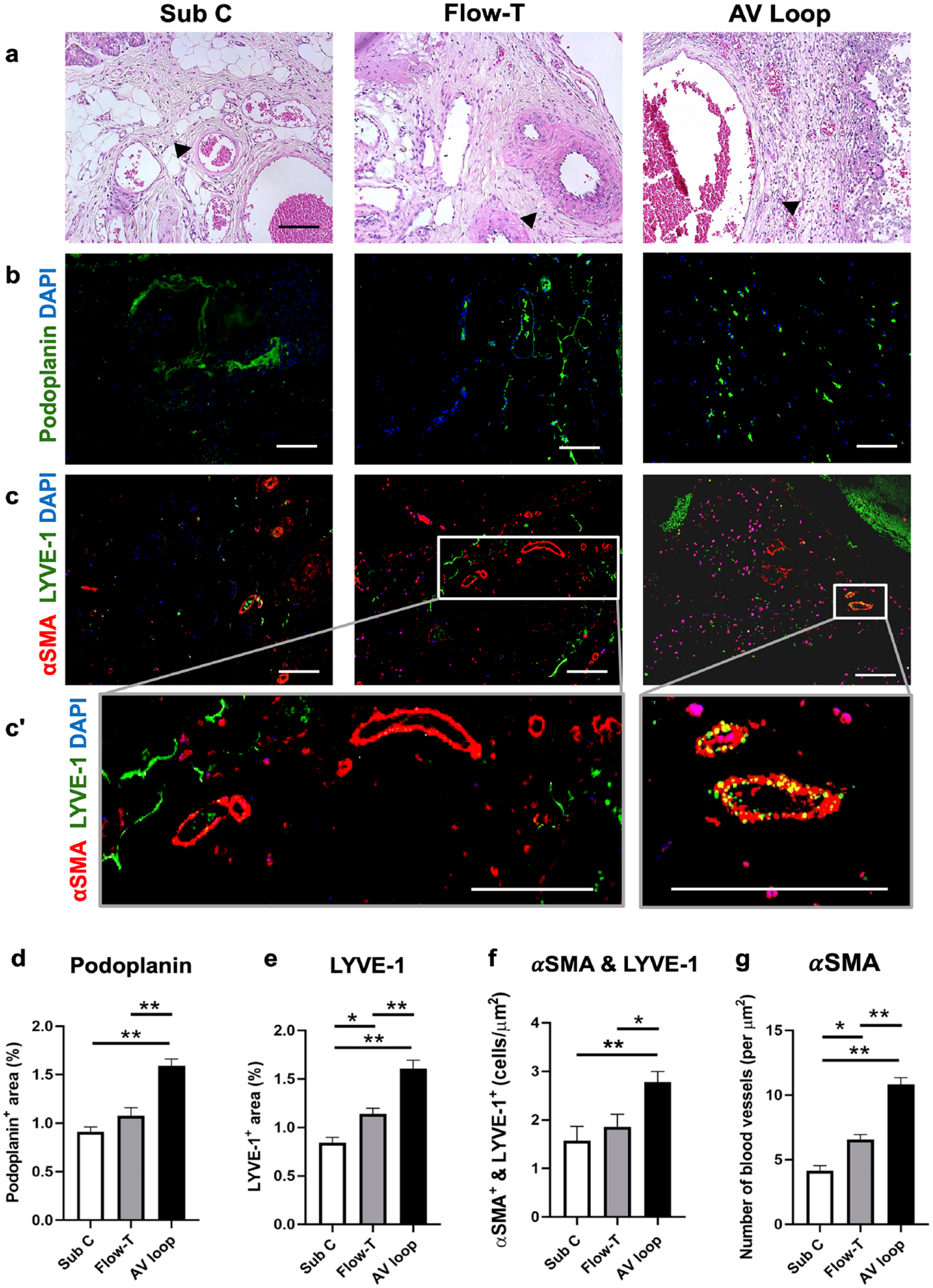
H&E staining as well as immunofluorescence staining of the three hemodynamic models: (a) microscopy images of H&E-stained fibrin hydrogels with suspended LECs in the Sub C, Flow-T, and AV loop model 2 weeks after implantation. Arrowheads: LECs. The lymphatic vessel was stained by lymphatic markers, (b) podoplanin (Green), and (c) LYVE-1 (Green). (c’) The zoom in image of angiogenesis in flow through group and collecting lymphatic vessel in the AV loop group. Quantification of cells expressing (d) podoplanin and (e) LYVE-1 as percentage of the same microscope field of view. Quantification of the (f) αSMA and LYVE-1 co-expressing cells and (g) αSMA expressing cells. Scale bar equals 100 μm in all images. n = 6. Error bar = SEM.
The level of lymphangiogenesis was investigated using immunofluorescence staining for podoplanin and LYVE-1 (Figure 3(b) and (c)). A significantly higher expression of podoplanin in terms of percentage of area per field of view was exhibited in the AV loop model compared to the Sub C model and the Flow-T model (AV loop vs Sub C: 1.6 ± 0.07 % vs 0.91 ± 0.05 %, p < 0.001; AV loop vs Flow-T:1.6 ± 0.07% vs 1.1 ± 0.08%, p < 0.001; Figure 3(b) and (d)). The expression of podoplanin in the Flow-T and Sub C models, however, was similar. The expression of LYVE-1 was significantly higher in the AV loop model, followed by the Flow-T model (AV loop vs Sub C: p < 0.001; AV loop vs Flow-T: p < 0.001; Figure 3(c) and (e). αSMA in co-expression with LYVE-1 has been shown to stand for the presence of functional lymphatic vessels capable of fluid transportation via contraction of smooth muscle cells.32,33 The co-expression of αSMA and LYVE-1 was significantly higher in the AV loop model compared to the other two models (AV loop vs Sub C: p < 0.001; AV loop vs Flow-T: p < 0.05; Figure 3(c)). The co-expression of αSMA and LYVE-1 in the Sub C group and the Flow-T group was similar (p = 0.73). The tubular structure of collected lymphatic vessels with both staining of αSMA and LYVE-1 was observed in the AV loop group, whereas more lymphatic capillaries with only LYVE-1 staining were displayed in Sub C group and the Flow-T group, and the higher presence of αSMA in the flow through group in comparison to Sub C group was mostly angiogenesis (Figure 3(c’)). In addition to lymphangiogenesis, the number of blood vessel marked with αSMA staining in the AV loop model was significantly enhanced compared to that in the other two models (AV loop vs Sub C: 11.0 ± 0.52 vs 4.1 ± 0.4, p < 0.001; Flow-T vs Sub C: 6.6 ± 0.37 vs 4.1 ± 0.4, p = 0.01; Figure 3(g)). The results indicate that a vascular scaffold likely promotes lymphangiogenesis by enhancing the capillary lymphatic formation and angiogenesis with increased expression of αSMA. However, the formation of functional lymphatic vessels was only significantly enhanced in the AV loop model.
AV loop model promotes the expression of VEGF-C and VEGFR-3
VEGF-C as a crucial growth factor 34 for lymphangiogenesis, and so is VEGFR-3 as its receptor, both are indicators for lymphangiogenesis. 35 The expression of VEGF-C and VEGFR-3 are both significantly higher in the AV loop model (Figure 4(a) and (b)) compared to the Sub C model (VEGF-C: AV loop vs Sub C:1.5 ± 0.08 % vs 1.1 ± 0.06%, p = 0.001; VEGFR-3: AV loop vs Sub C:1.5 ± 0.09 vs 1.0 ± 0.05, p < 0.01), and a tendency of higher expression but not significantly different compared to the Flow-T model (Figure 4(c) and (d)). The results suggested that both the secretion of VEGF-C and the presence of VEGFR-3 were promoted in the vascular models, especially in the AV loop model.
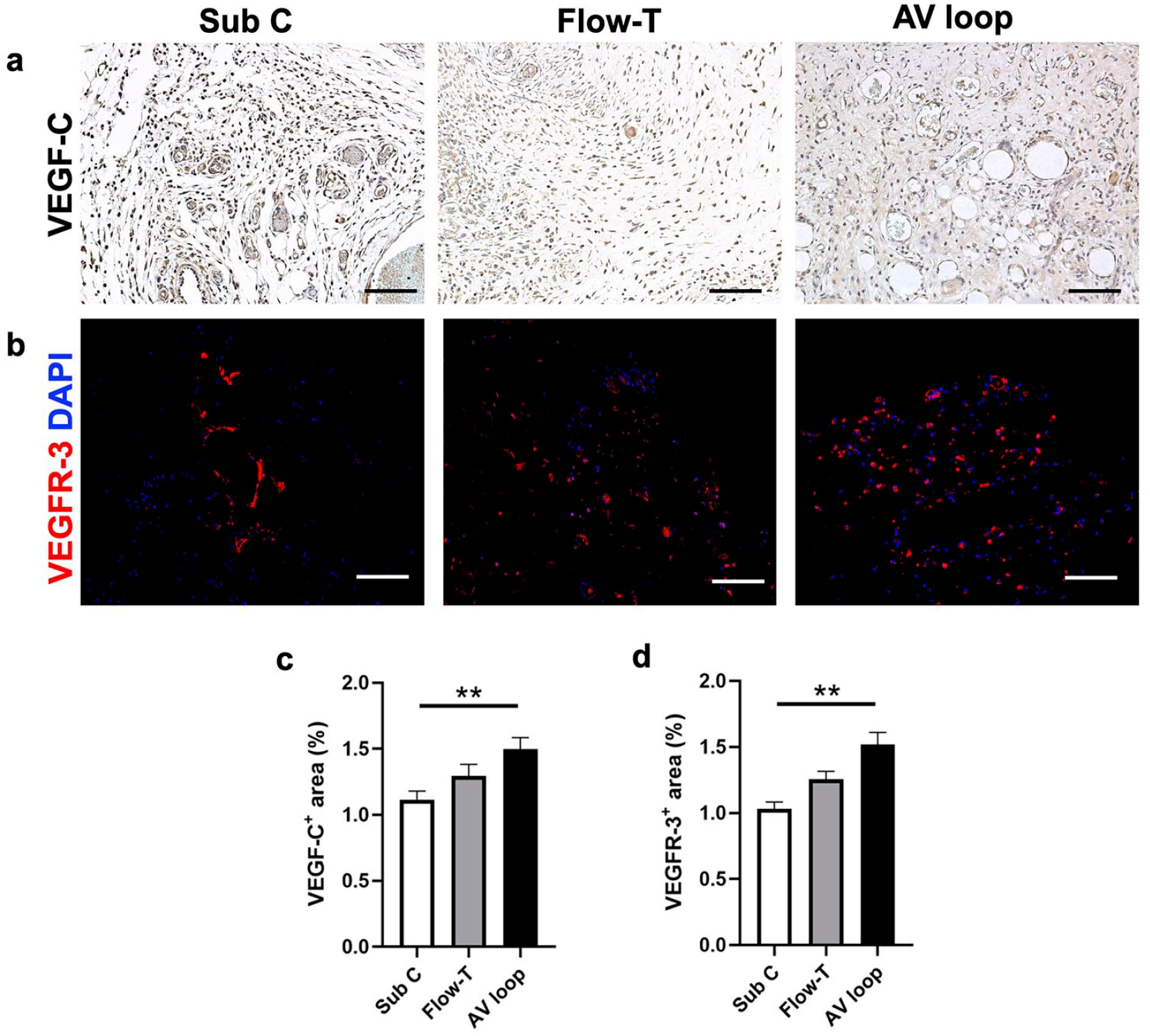
Expression of VEGF-C and VEGFR-3 in different hemodynamic models: (a) immunohistochemistry staining of VEGF-C in different hemodynamic models, (b) immunofluorescence staining of VEGFR-3. The quantification of (c) VEGF-C and (d) VEGFR-3 expression area. Scale bar equals 100 μm. n = 6. Error bar = SEM.
Protein expression of lymphangiogenesis related genes enhanced in AV loop model
The protein expression of the lymphangiogenesis related genes was higher in the AV loop model in the conducted Western blot (Figure 5). The relative expression level of LYVE-1, Prox1, and podoplanin was at least three folds higher in the AV loop model than in the Sub C or Flow-T model. The expression even increased approximately six folds in VEGFR-3 expression in the AV loop model (Figure 5).
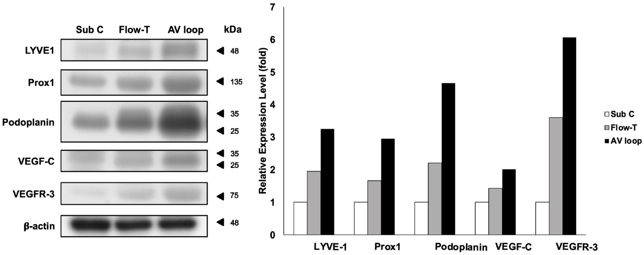
The results of western blot analysis on proteins involved in lymphangiogenesis including the expression of LYVE-1, Prox1, podoplanin, VEGF-C, and VEGFR-3 in different hemodynamic models. β-Actin was used as the internal control for the proof of equal loading on each sample. The fold changes based on Weston blot results was presented. n = 6.
Inflammatory reactions in different models
Temporary lymphangiogenesis or lymphatic remodeling has been shown to be a response to inflammation. 36 Little is known about the inflammatory responses under the influence of different hemodynamic environments. Figure 6 illustrates and quantifies the presence of CD3, CD4, and CD8 cells via immunofluorescence staining per view area. The Sub C model showed a significantly higher presence of CD3 cells representing a higher T cell inflammatory response compared to both the Flow-T and the AV loop model (Sub C vs Flow-T: 3.7 ± 0.15 vs 1.8 ± 0.20 cells/μm2, p < 0.001; Sub C vs AV loop: 3.7 ± 0.15 vs 2.5 ± 0.15 cells/μm2, p < 0.001; Figure 6(a)). The highest presence of CD4 cells was found in the AV loop group, but the difference was not statistically significant, while the Sub C and Flow-T displayed similar values (Sub C vs Flow-T: p = 0.90; Sub C vs AV loop: p = 0.18; Figure 6(b)). The presence of CD8 cells was elevated in the Sub C model compared to the Flow-T and AV loop model, however not significantly (Sub C vs Flow-T: p = 0.40; Sub C vs AV loop: p = 0.63; Figure 6(c)). The results suggest that the inflammatory reaction was lower under a stronger flow stimuli environment.

Immunofluorescence staining of inflammation markers: (a) CD3, (b) CD4, and (c) CD8 in different hemodynamic models. Scale bar equals 100 μm. n = 6. Error bar = SEM.
The influence of the addition or absence of LECs
The H&E staining and histologic investigation showed that there was less cellular infiltration without the addition of LECs (Figure 7(a)). The expression of lymphatic markers podoplanin and LYVE-1 was significantly higher with the addition of LECs (podoplanin: p < 0.01; LYVE-1: p < 0.001; Figure 7(b)–(e)). There was also a significantly higher number of cells per square meter with the addition of LECs in both α-SMA as well as in the co-expression of α-SMA and LYVE-1 (Figure 7(f) and (g)). (with LECs vs without LECs: 2.7 ± 0.22 vs 1.1 ± 0.1, p < 0.01). VEGF-C and VEGFR-3 both showed a significantly higher expression with the addition of LECs (Figure 7(h) and (i)).

The investigation of lymphangiogenesis in the AV loop model with and without the addition of LECs: (a) H&E staining and histologic images of the AV loop model with only fibrin hydrogel (left) and fibrin hydrogel with LECs (right) 2 weeks after in vivo implantation of the vascularized scaffold. Immunofluorescence of the tissue with the lymphatic markers (b) LYVE-1 (green) and (c) podoplanin (green). Quantification of expression area (%) of (d) podoplanin and (e) LYVE-1 with and without LECs addition. The numbers of staining cells per square µm of (f) α-SMA and LYVE-1 and (g) α-SMA. Histological staining images of (h) VEGF-C without (left) and with (right) LECs in the AV loop model. Quantification of VEGF-C expression was also presented. (i) Immunofluorescence of VEGFR-3 without (left) and with (right) LECs in the AV loop model. Bar graph showing results of the relative expression (%) of (h) VEGF-C and (i) VEGFR-3 without and with LECs. (j) Western blot analysis of protein expression level of LYVE-1, Prox1, podoplanin, VEGF-C, and VEGFR-3 in the AV loop model with and without the addition of LECs. β-Actin was used as the internal control for the proof of equal loading on each sample. The immunofluorescence staining of (k) CD3, (l) CD4, and (m) CD8 in the AV loop model with and without the addition of LECs in the fibrin hydrogel. The number of cells per square µm of CD3, CD4, and CD5 were presented respectively, in the presence and absence of LECs. (n) The expression of angiogenesis genes, CD31, FGF-2, and VEGF-A in the AV loop model with and without the addition of LECs to the fibrin hydrogel used. Scale bar equals 100 μm. n = 6. Error bar: SEM.
Similar to the histological findings, the results of the Western blot showed an increased expression of the protein level of LYVE-1, Prox1, podoplanin, VEGF-C, and VEGFR-3 under the addition of LECs (Figure 7(j)). The infiltration of mature CD8 T-cells was significantly reduced with the addition of LECs (p < 0.001), whereas CD3 and CD4 cells showed an increase under the presence of LECs, but not reach to significance (CD3: p = 0.42; CD4: p = 0.09; Figure 7(k)–(m)). In all, the results suggest that the expression of LYVE-1, podoplanin, VEGF-C, and VEGFR-3 were promoted under the presence of LECs.
Next, we investigated the expression of angiogenesis related genes, CD31, VEGF-A, and FGF-2. Unlike LYVE-1 and other lymphangiogenesis related gens, the expression of CD31 presented a significantly higher relative expression when LECs were not included (without LECs vs with LECs: 0.03 ± 0.007 vs 0.01 ± 0.001, p < 0.05; Figure 7(n)). Similarly, VEGF-A also showed a decreased expression under addition of LECs, however not significant (p = 0.392; Figure 7(n)). FGF-2 demonstrated a higher, yet non-significant relative expression under the addition of LECs (p = 0.49). Overall, the results suggest that the inclusion of LECs promoted lymphangiogenesis; on the other hand, angiogenesis was highly promoted with the abscise of LECs.
iNOs and eNOS relative expression dependent on the hemodynamic model and on the presence or absence of LECs in the AV loop model
Endothelial nitric oxide synthase (eNOS), inducible nitric oxide synthase (iNOS), and neuronal nitric oxide synthase (nNOS) are three isoforms of the nitric oxide synthase. 37 Blocking the supply of nitric oxide with the NOS inhibitor L-NMMA, hindered the regeneration of lymphatic vessels, 38 suggesting that the NOS family involves in lymphatic vessel formation. The expression of eNOS and iNOS in the three different hemodynamic flow models was investigated in terms of their effect on lymphangiogenesis. Our results showed that the relative expression of iNOS was significantly increased, approximately 5 folds, in the AV loop model compared to the Sub C model and had the lowest values in the Flow-T model (Figure 8(a)). Unlike iNOS, eNOS expressed similarly in all three models. Besides, the inclusion of LECs seemed to enhance the expression of both the iNOS and the eNOS of more than 1.5 folds in the AV loop model (Figure 8(b)).

The results of western blot analysis on protein level of iNOS and eNOS: (a) in three different hemodynamic models and (b) The protein level of iNOS and eNOS in the AV loop model with and without the addition of LECs. β-Actin was used as the internal control for the proof of equal loading on each sample. The fold changes based on Weston blot results was presented.
Discussion
Although recent studies support a non-venous origin of the LECs, the parallel orientation of the collecting lymphatic vessels and major veins still suggests the possibility that venous flow may play an important role in remodeling lymphatic regeneration. An in vivo scaffold equipped with a vein can likely provide a similar environment to guide lymphangiogenesis. Besides, the hemodynamic flow stimulus was considered an effective promoting factor for lymphangiogenesis. The role of flow stimuli in lymphangiogenesis was explored by other researches, showing that the combination of fibrin-containing scaffolds with VEGF and LECs within a chamber with a blood flowing through promotes lymphangiogenesis for tubing organization in vivo. 27 Considering that the hemodynamic force can be an effective promoter for lymphangiogenesis, three hemodynamic models representing different flow rates were created in this study to investigate the relationship between different hemodynamic force models and lymphangiogenesis. The expression of podoplanin and LYVE-1 were significantly higher in the AV loop model compared to the other two groups. Besides the promotion of lymphangiogenesis, the AV loop model exhibited higher numbers in the functional lymphatic vessels labeled with co-expression of αSMA and LYVE-1 markers, suggesting that stronger hemodynamic force enhances the formation of functional lymph vessels.
VEGF-C is involved in the process of LECs sprouting from veins to form initial lymphatic vessels. 39 In VEGFR-3 mutant mice, the lymphatic growth was hindered while blood vessels developed normal, indicating that VEGFR-3/VEGF-C signaling is vital in the process of lymphangiogenesis. 40 Compared to the Sub C and Flow-T models, our results demonstrate that the AV loop model with the higher flow stimuli enhanced lymphatic vessels formation partly by elevating the VEGF-C/VEGFR-3 signaling. Further, lymphangiogenesis usually occurs in an inflammatory setting in pathological situations, tumor metastasis, or tissue repair.41,42 Other than increased VEGF-C/VEGFR-3 signaling caused by hemodynamic force, the changes regarding inflammatory reactions were also investigated. The number of infiltrated CD4+ and CD8+ cells showed no notable changes within these three models, but the infiltration of CD3+ cells increased in the Sub C model. The results suggest that the enhancement of lymphangiogenesis was mainly caused by the increase of VEGF-C/VEGFR-3 signaling, resulting from the comparatively higher hemodynamic force rather than an accompanying inflammatory reaction.
An increase in blood flow results in an increase of shear stress, which is defined as the frictional force generated by the flowing blood on the vessel wall. 43 In the current study, we included two vascular pedicle models: the AV loop model and the flow through model. It has been confirmed in previous studies that the vascular bud predominantly originates from the vein instead of the artery. 44 With the creation of an AV loop, the thin-walled vein that is connected to the artery faces a high flow. This results in an increased budding of the vessels during angiogenesis. The numbers of vessel budding during angiogenesis is even more in the vein of the AV loop model because of the stronger flow from the artery to the vein graft. The microvascular anastomosis also produces endogenous fibrin deposition via the anastomosis site, which contributes to angiogenesis as well. 45 Our objective was the comparison of the two vascular models in terms of the difference in angiogenesis and lymphangiogenesis regarding the difference in vascular flow, since an increased flow velocity may stimulate the production of nitric oxide (NO) from endothelial cells.46,47 Our results suggest that the AV loop model not only enhances angiogenesis but also lymphangiogenesis. The shear stress is stronger in the AV loop model, and the shear force drives more extravasation of inflammatory exudates and cells and subsequent angiogenesis and lymphangiogenesis. 48 Besides the inflammatory reaction, the angiogenesis, and the lymphangiogenesis, we also investigated the NO pathway in the different vascular models. The role of the NO pathway in modulating vascular formation and angiogenesis has long been confirmed as well as its association with hemodynamic shear stress. Hemodynamic stress activates eNOS and thus leads to the production of NO.49,50 iNOS was found to be released by LECs in an inflammatory situation. 51 Its secretion from LECs also plays a role in lymphangiogenesis in cancer metastasis. For example, in human squamous cell carcinoma cell lines, the positive correlation between iNOS activities and VEGF-C was found as a leading factor in the promotion of lymphangiogenesis. 52 Moreover, genetic deletion of eNOS hindered the process of lymphatic metastasis. 38 In our studies, the protein expression level of iNOS presented significantly higher in the AV loop model, suggesting that the higher hemodynamic force enhances the presence of iNOS in lymphangiogenesis. A slightly increased expression of eNOS and an elevated expression of VEGF-C/VEGFR-3 was also found in the AV loop model. These results suggest that the higher hemodynamic force present in the AV loop model stimulates the synthesis of eNOS and iNOS and subsequently mediates VEGF-C-induced lymphangiogenesis. Adding LECs to the AV loop model also significantly increases the expression of iNOS and eNOS. The results indicate that not only an increase of hemodynamic force but also the presence of LECs promote the lymphangiogenesis through the increase of eNOS and iNOS.
The results of this study indicate that the AV loop model presented the most promising results on lymphatic vessel regeneration. However, the scaffold generated from AV loop model without LECs drastically reduced the number of LYVE-1 labeled cells and functional lymphatic vessels, suggesting that an increased flow force alone is not sufficient to promote the lymphangiogenesis process. Moreover, the expression of angiogenesis genes, CD31 and VEGF-A, were significantly increased in the AV loop camber without LECs. The results suggest that the hemodynamic force without the addition of LECs created an environment promotional to angiogenesis and not so much for lymphangiogenesis, suggesting that the presence of LECs is essential for lymphangiogenesis.
Several significances were observed in this study. First of all, the inclusion of a vascular pedicle, both in the Flow-T and AV loop models, promoted lymphangiogenesis. With it, the development of the vasculature within the engineered tissue and a long-term survival and maintenance of the engineered tissue can be expected. Second, our design to include three different models was based on the fact that the dynamic venous flow was reported as a guidance of lymphangiogenesis during the embryo stage, even the valve forming process. 53 The AV loop model provides an even stronger flow stimulus with vascular dilatation and stimulates the expression of NOS to promote the process of lymphangiogenesis. The application of vascular models into lymphatic tissue engineering not only provides a microenvironment for mechanical transduction in lymphangiogenesis with the inclusion of LECs, but also enhances angiogenesis in the engineered graft. The engineered lymphatic tissue becomes vascular, and the inclusion of a pair of vascular pedicles also brings the potential of future transfer of the engineered lymphatic tissue in the form of a free tissue transfer. As reported, 23% of the grafts can be vascularized and the structure can be maintained for up to 16 weeks, 45 the engineered vascularized lymphatic tissue has the potential to be transferred for the management of lymphedema.
Conclusion
In conclusion, lymphatic tissue engineering can successfully be conducted using an AV loop model, which demonstrated better lymphangiogenesis in comparison to the Sub C model and the Flow-T vascular pedicle model. Besides the hemodynamic shear forces, the supplement of LECs is required for lymphatic vessel regeneration. The in vivo scaffold generated from AV loop model can provide more flexible biomaterials for the replacement of missing lymphatic tissue and enhance lymphatic drainage in the clinical treatment of lymphedema.
Footnotes
Acknowledgements
We sincerely thank Miss Ingrid Kuo and the Center for Big Data Analytics and Statistics (Grant CLRPG3N0011) at Chang Gung Memorial Hospital for creating the illustrations used herein. We also to acknowledge the Laboratory Animal Center, Chang Gung Memorial Hospital, Linkou, for its assistance in animal housing.
Authorship
Conceptualization, JJH and HYH; data curation, JJH and HYH; formal analysis, HYH, YCC, and JWL; funding acquisition, JJH and HYH; investigation, HYH, GAM, YCC, JWL, FCSC, and JJH; supervision, JJH and HYH; writing—original draft, HYH, GAM, YCC, JWL, and JJH; writing—review and editing, HYH, GAM, FCSC, and JJH. All authors have read and agreed to the published version of the manuscript.
Availability of data and materials
The data used and analyzed during the current study are available from the corresponding author upon request.
Declaration of conflicting interests
The author(s) declared no potential conflicts of interest with respect to the research, authorship, and/or publication of this article.
Funding
The author(s) disclosed receipt of the following financial support for the research, authorship, and/or publication of this article: This work was supported and funded by the Ministry of Science and Technology, Taiwan (MOST-110-2314-B-182-047-MY3) and Chang Gung Memorial Hospital (CMRPG3K1581).
Ethical approval
The animal experiments were performed under the guidelines of the animal center of Chang Gung Memorial Hospital (IACUC# 2020062902 and 2020122216).
Informed consent
Not applicable.
Human rights
Not applicable.