
Abstract
Recently there has been an observed change in security policy across the globe which implies that humanity must prepare for hybrid and asymmetric acts of war. This security situation will result in spontaneous attacks from non-military groups. The threats include ballistic attacks from commercially available weapons, detonation of explosives, and impact of vehicles. These attacks are focused on critical infrastructures. Reinforced concrete (RC) elements with ballistic and explosion protection are of huge relevance. This requires new concepts and innovative solutions for the protection of new buildings and/or for the strengthening of existing structures. In this paper a method for the increase of structural safety is shown using Ultra-High Performance Fiber Reinforced Concrete (UHPFRC) or sprayed UHPFRC, so called UHPFRSC, as a surface layer for reinforced concrete structures. The UHPFRC/UHPFRSC is applied in thin layers of 30 - 80 mm on the protection side. The interaction of the two different cementitious materials results in increased resistance to high dynamic loads. The traditional reinforced concrete on the impact side absorbs a major fraction of the energy of impact. On the back side (protection side), tensile forces are generated by the impact, which can excellently be handled by the UHPFRC/UHPFRSC. For proof of concept of the hybrid strengthening method, tests were carried out on UHPFRC - RC composite elements. In the test campaign, ballistic tests were performed using test specimens with dimensions of 500 × 500 mm. The layer thicknesses were 120 mm reinforced concrete and 40 mm UHPFRC. Additional steel rebars in the UHPFRC layer were applied for half of the specimens. The investigation demonstrated the effectiveness of the strengthening method, showing high resistance to high-dynamic loads. This behavior is attributed to the absorption and transfer of tensile stresses by the UHPFRC, that reduces penetration depth and damage, ensuring remaining load-bearing capacity after gunfire.
Keywords
Introduction
Worldwide, a change in security policy can be observed. In the past wars were fought between nations and combatants, but now and in the future, all those involved will increasingly have to adjust to hybrid and asymmetric threat situations. Due to increased security situations, spontaneous attacks from civilian groups - terrorism, organized crime, etc. - will become more frequent.
The goal of the research is to react to this changing risk scenario and to increase the protection of citizens with innovative and application-oriented structural methods for protection against high-dynamic impacts from gunfire and contact detonation. A layer of Ultra-High Performance Fiber Reinforced Concrete; (UHPFRC) can be used for strengthening existing structures with user-friendly technologies.
Impact or blast of solids causes forces that are transmitted in the form of stress waves inside the structure. In the case of shock waves, they are emitted from the point of impact into the inner side of the component and cause spalling on the attack side. On the protective side, the waves reflect and induce a traction wave. This causes scabbing on the protective side of the specimen. Due to tensile failure, scabbing (e.g., concrete) is thrown in the direction of the projectile (Gebbeken et al., 2009; Wensauer, 2014; Zukas et al., 1983).
To deal with these growing requirements efficiently, there is a variety of strengthening methods and approaches, e.g., (Michal, 2014; Zohrabyan et al., 2020; Zohrabyan et al., 2022).
Currently, UHPFRC is applied for the repair and/or strengthening of reinforced concrete structures in the area of infrastructure (Brühwiler, 2017). In addition to its high compression strength, UHPFRC is characterized by a very dense structure, high ductility and high resistance to tensile forces. Due to the low water-binder ratio, an optimized packing density and the reactive additives, a very dense microstructure with low porosity is generated. High-strength steel microfibers with tensile strengths above 2000 MPa, a diameter D ≤0.20 mm and a length of 8 to 15 mm are usually used for the fiber reinforcement. The fibers lead to an increase in the tensile strength of the composite material and a more ductile material behavior.
Furthermore, under specific conditions (high fiber content, fiber orientation, etc.), a strain-hardening behavior can be achieved and in consequence a multi-crack formation can be generated, comparable to a crack distribution effect of reinforcement in reinforced concrete. Thus, a micro-crack does not open further, but secondary cracks appear. The crack spacing is only a few millimeters and the crack width is smaller compared to cracks in reinforced concrete with conventional steel rebars (Jungwirth, 2006). The compressive strength of UHPFRC is usually 150 to 250 MPa, the tensile strength is nine to 15 MPa and the modulus of elasticity is 45 to 55 GPa (Bhusari and Gumaste, 2017; Graybeal, 2006; Schmidt et al., 2008).
Experimental studies have shown that the fracture energy of UHPFRC is significantly higher than that of conventional concrete (Wahba et al., 2012). This characteristic energy absorption capacity, along with a resistance to scabbing, spalling, and fragmentation, makes it an ideal material for use as a protection layer (Li et al., 2015a, 2015b; Millard et al., 2010; Othman and Marzouk, 2016; Rebentrost and Wight, 2011; Yi et al., 2012).
In a research project at the Munich University of Applied Sciences, the use of Ultra-High Performance Fiber Reinforced
Strengthening concept
The development of a strengthening method for buildings of the critical infrastructure made of reinforced concrete using UHPFRC/UHPFRSC is currently ongoing. The innovative material provides optimal characteristics for this application, so that an increase in the resistance to high dynamic impacts can be achieved, see Figure 1 for the example with gunfire. Applying a thin layer of UHPFRC/UHPFRSC enables strengthening of existing structures with only reducing the usable space by a minimum. The mechanism of strengthening with UHPFRC against high-dynamic impact.
The combination of the different stiffnesses of the two cementitious materials and the high tensile strength of the UHPFRC/UHPFRSC enables a high dissipation of energy. The less stiff normal-strength concrete on the attack side takes the first impact and diffuses it over the depth. The tensile stresses generated in the 30-80 mm thick additional UHPFRC/UHPFRSC layer are dissipated by the fibers. Simultaneously, this results in a multi-axial state of stress in the normal strength concrete (NSC), which causes a significant increase its resistance. In the composite joint as well as through the crack formation in the UHPFRC/UHPFRSC, there are further potentials for the dissipation of the impact and the additional possibility of deviating the projectiles in the discontinuity zone. Thus, bullet penetration and scabbing are prevented on the protective side. As the UHPFRC/UHPFRSC interior layer is showing no scabbing, the technical equipment that is anchored to the structure is protected from breakout and falling. These are, for example, power lines that are needed for safe operation. Thus, the operation of the critical infrastructure is assured.
Preliminary tests at the University of Armed Forces Munich and Munich University of Applied Sciences showed the high effectiveness of the strengthening method. A wide research project is launched to bring the technology to service and establish instructions for application so that the load-bearing behavior can be described and the use of the technology can be ‘planned’ using standard engineering design approaches. The cooperation partner Kompetenzzentrum materielle Sicherheit (KMS) has run a preliminary study in the context of this experimental study within the German program “Zukunft Bau” (van der Woerd and Fischer, 2020), where a catalogue of building components for structural protection has been established (Solass et al., 2021). An essential result of the project is the requirement for strengthening methods for building and perimeter demarcations. In practice, these structures mainly consist of vertical reinforced concrete components. The demand identified from this is to be addressed by the present research.
Fabrication and material properties
Mixture design of NSC and UHPFRC.
For the experimental investigation the mix-design “M3Q” UHPFRC was used according to (Fehling et al., 2005). This mixture contains cement, quartz sand, quartz powder, silica fume and superplasticizers with a maximum grain size smaller than 1 mm. The exact composition can be taken from Table 1. High-strength steel wire fibers with a diameter of 0.175 mm and a length of 12.5 mm are used as fiber reinforcement. The tensile strength of the steel micro fibers used for the UHPFRC is typically between 2000 and 3000 N/mm2. To ensure a strain-hardening effect in the post-cracking stage, a steel fiber content of 2.5 % by volume was used. The compressive strengths and the modulus of elasticity were determined according to the Swiss standard SIA 2052 (SIA2052, 2016). The compressive strength was tested on cubes of 150 mm at the day of high-dynamic testing after 49 days of hardening. The modulus of elasticity was determined on cylinders according to SIA 2052 (SIA2052, 2016) with the dimensions d/h = 100/200 mm also after 49 days. The specimens were stored according to normative standards. The average compressive strength results in fcm,cube,49d = 162.11 N/mm2 and the E-modulus in Ecm,49d = 51.10 kN/mm2. Based on the observed material characteristic the material could be classified as UHPFRC according to SIA 2052 (SIA2052, 2016). The existing material characteristics correspond to the properties of the M3Q, so it can be assumed that the corresponding tensile strengths can be taken from the literature with 9-15 N/mm2. This material properties of the used UHPFRC are comparable to the properties of UHPFRSC, so that the concept with this material is representative for both ultra-high strength materials.
As rebar reinforcement type B500 B according to DIN EN 10080 was used. Before placing the reinforcement, the steel was stored in dry conditions and protected from external influences. The reinforcement was installed and concreted according to the geometric requirements and also according to generally approved requirements. The reinforced concrete base element was concreted in wooden formwork according to generally approved requirements. Compaction and curing of the normal concrete were also carried out conform to regulations. The surface of the reinforced concrete was roughened using high-pressure water jetting after 24 h, which corresponds to the condition of surface preparation for repair work. The prepared surface conforms to the requirement of a ‘rough surface’ according DIN EN 1992-2. After a 7-days hardening the UHPFRC layer was added to the reinforced concrete base element. The concreting procedure of UHPFRC and resulting fiber alignment is schematically shown in Figure 2(a). The surface was sprayed with water repeatedly for 12 h before concreting. Concreting, compaction and curing of the UHPFRC were performed. Accurate curing was applied to minimize constrained stresses. The specimens were stored under laboratory conditions until testing. (a) Schematic concreting procedure of UHPFRC and qualitative fiber alignment, (b) Geometry and reinforcement of the specimens.
Experimental investigation
Specimens
Two different specimen configurations with two different conditions each were produced and tested. The plates consisted of 500 mm wide, 500 mm long, and 120 mm high reinforced concrete base element with rebars of ∅8 mm and a bar spacing of 90 mm. This reinforcement was added orthogonally in top and bottom layer. The length of the steel bars was 540 mm and protruded 20 mm each side of the concrete body. The concrete cover of the steel bar reinforcement in the reinforced concrete was 15 mm. Furthermore, a bar reinforcement for the composite was placed around the edge of the specimen by using ∅8 mm stirrups. The dimensions of the test specimen were significantly smaller than those of a real element, therefore dowelling the joint was chosen to imitate transfer effects.
The UHPFRC layer was applied on the surface of the base body with a thickness of 40 mm. The layer thickness was set according to the recommendation for the repair and strengthening of UHPFRC in the area of infrastructure buildings (Brühwiler, 2020). The goal was to show the enhancement of impact resistance using a minimally thin additional layer with the least possible weight. The UHPFRC layer of 40 mm represents the minimum thickness, as a minimum concrete cover is required. Because for half of the specimen, a steel rebar reinforcement with ∅8 mm steel rebars with 90 mm spacing were added. Due to the intersection points of the two orthogonally arranged steel rebar reinforcement in the UHPFRC, the concrete cover is reduced to only 12 mm. The authors considered any further reduction in concrete cover impractical, as it must ensure both the mechanical integration of the steel rebar reinforcement and realistic manufacturability. For the rest of the elements the UHPFRC layer was fabricated without rebars. Geometry and steel rebar reinforcement of the composite elements are shown in Figure 2(b).
Test setup
Ballistic tests were performed using hard-core projectiles on a typical shooting gallery. The test setup is shown in Figure 3. On the left-hand side, there is a shooting ram that is used to shoot the projectile and to precisely adjust the impact. The distance to the target plate is 12000 mm, shown on the right-hand side of the schematic illustration. The target plate is located in a closed frame. The frame serves as a support for the specimen and catches fragments that penetrate or break out. Furthermore, the frame contains surrounding linear support for the test specimen. On each outer line of the composite element, there is a load cell, which in total results in four measuring units. In addition, a camera system consisting of a high-speed camera and a high-speed flash for high-frequency imaging of penetrating projectiles is located at the backside of the test specimen. The device is used to determine the exit velocities of projectiles by optic measurements. There is a light barrier at a distance of 3000 mm from the projectile’s exit point at the end of the shooting stand’s barrel, and there is also a light barrier at a distance of 2500 mm from the target plate. The velocity of the projectile is determined for each light barrier so that the impact velocity can be extrapolated via the velocity loss between light barriers at the distance of 6500 mm. In connection with the load cells, it is possible to determine the energy. The experiments were carried out at the Faculty of Machine Engineering at the University of Armed Forces Munich. Test set-up for gunfire test.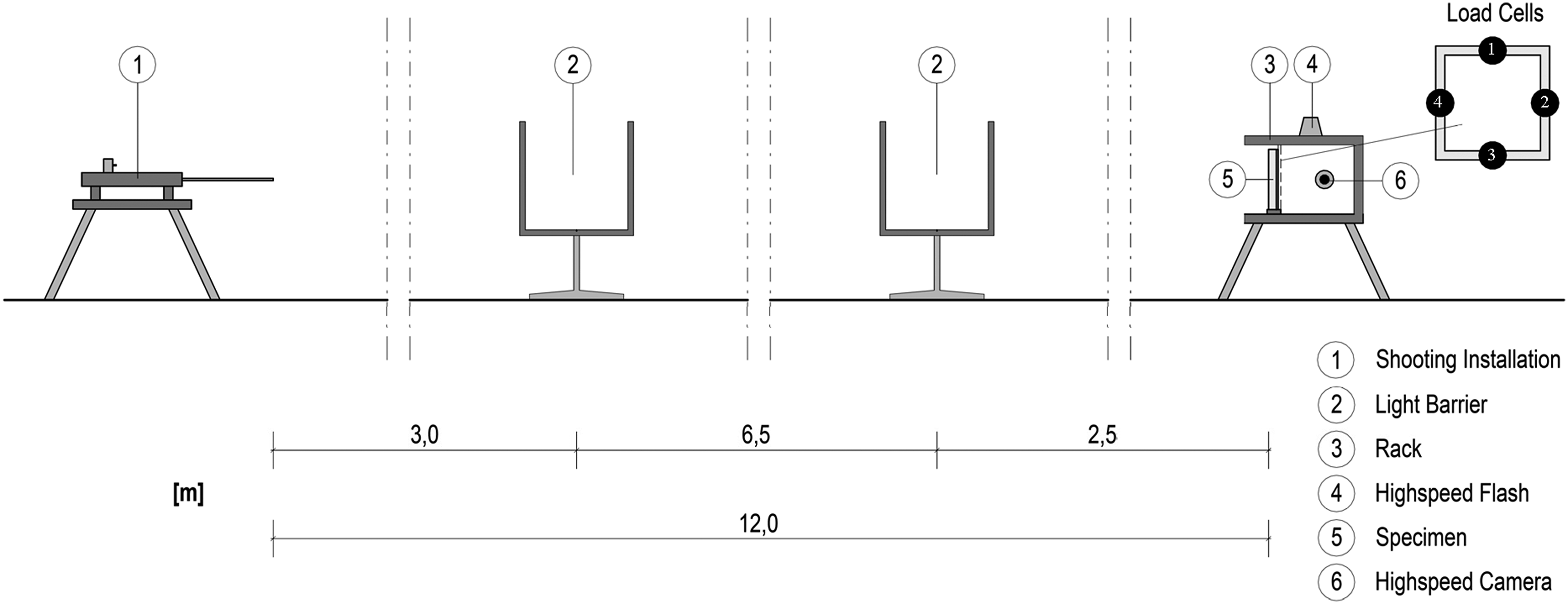
The projectile is a hard-core projectile named FN® 7.62 × 51 mm NATO cartridges, P80/1 Armor Piercing. It weighs 9.6 g and has a perforation of a 3.5 mm mild steel plate (NATO) of≥ 1100 m. Furthermore, the velocity is 823 m/s at 25 m.
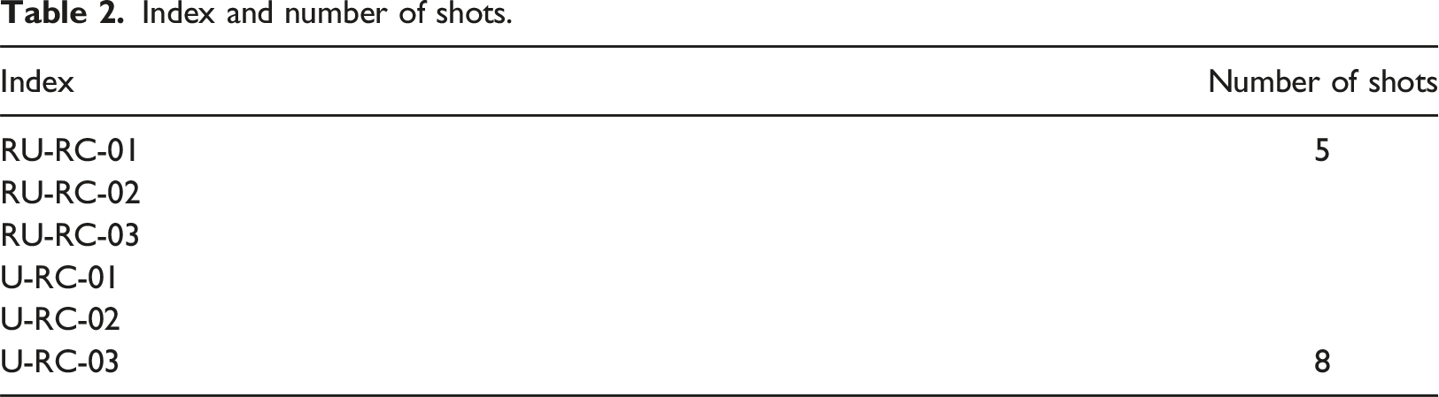
Index and number of shots.
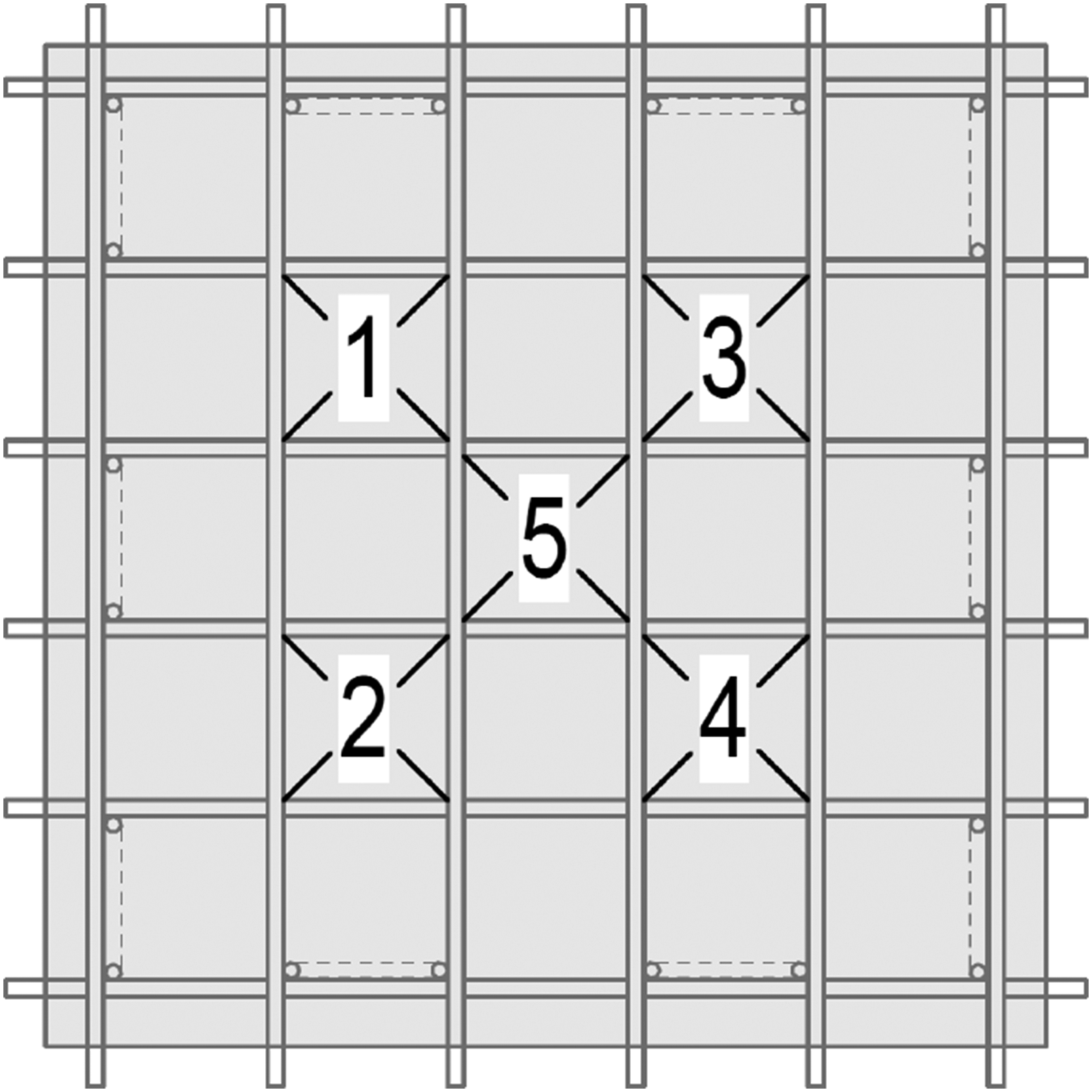
Arrangement of shots.
Testing and results
Figure 5 shows the test specimen U-RC-03 after the testing. Eight shots were placed at this specimen, with three more shots at position 5, resulting in a total of four impacts. The attack side of the test specimen can be seen in Figure 5(a); the surface of the reinforced concrete base element is shown. Furthermore, it can be observed that classic craters have formed in the reinforced concrete. The craters are also pronounced regarding the volume of the fracture. In addition, it can be recognized that the size of the crater becomes successively smaller per shot, which can be associated with the softening of the normal concrete due to the impact. An enlarged opening of the projectile canal at position five can be observed in comparison to the surrounding openings. The craters are so large that between positions three and five the steel bar reinforcement near the surface is uncovered. Test specimen U-RC-03 after testing (a) attack side (NSC); (b) protection side (UHPFRC).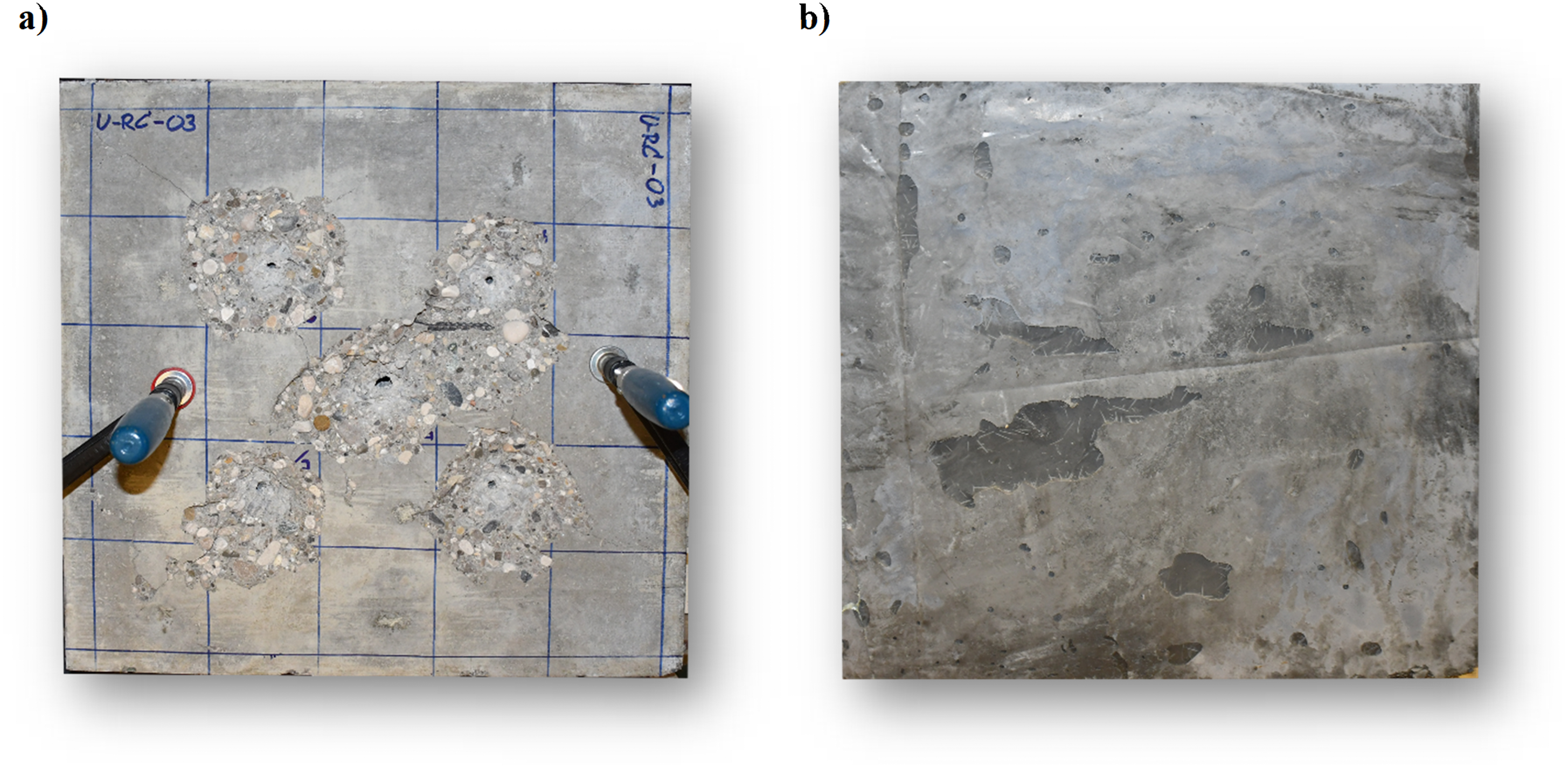
Figure 5(b) shows the UHPFRC on the protection side of the U-RC-03 composite element. In contrast to the attack side, no damage on the surface is visible. There are no breakouts and no macro cracks on the surface. The UHPFRC layer is undamaged. The visible dips are caused by the manufacturing process, and fibers close to the surface are also noticeable. These irregularities should not be interpreted as damage.
Results of the ballistic tests – Reihe U-RC-01/02/03 (values match the position of shots).
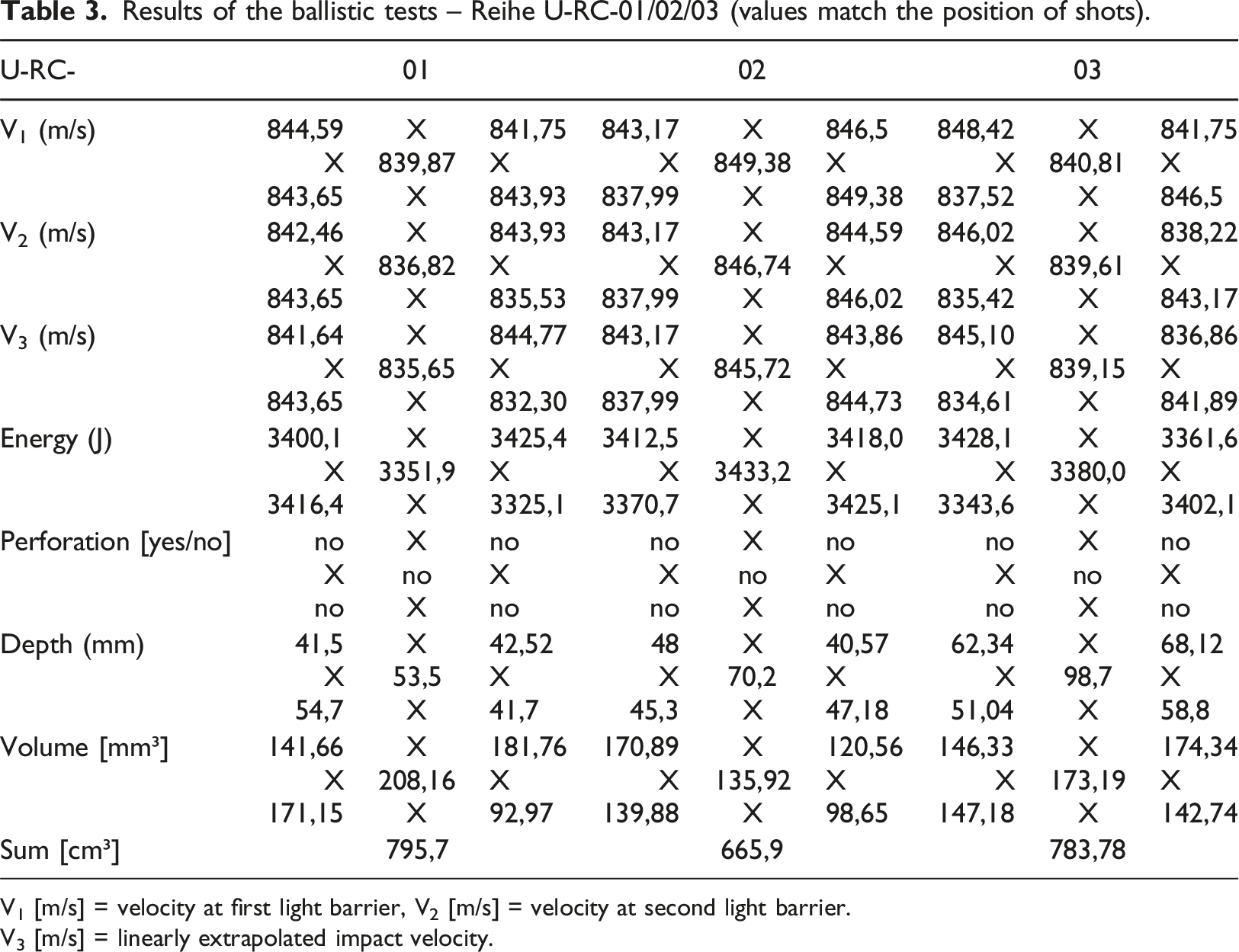
V1 [m/s] = velocity at first light barrier, V2 [m/s] = velocity at second light barrier.
V3 [m/s] = linearly extrapolated impact velocity.
Results of the ballistic tests – RU-RC-01/02/03 series (values match the position of shots).
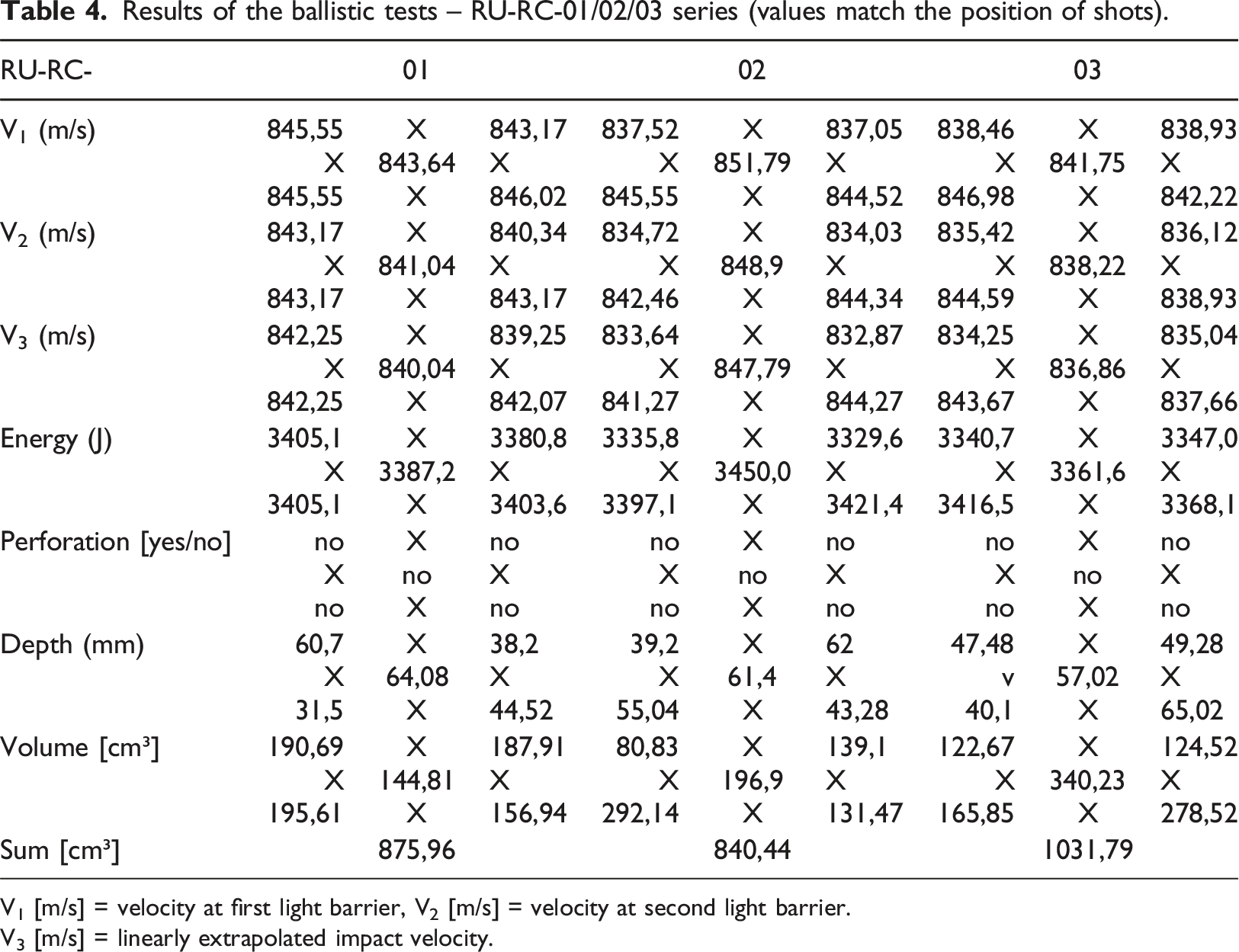
V1 [m/s] = velocity at first light barrier, V2 [m/s] = velocity at second light barrier.
V3 [m/s] = linearly extrapolated impact velocity.
For the determination of the crater volume, the respective specimen was photographed from all sides as basis-data using an ordinary camera. Subsequently, a true-to-scale 3D model was created on the computer (Zohrabyan et al., 2023).
Figure 6 shows representatively the digital volume determination after the ballistic test of specimen U-RC-01. This clearly shows how the phenomenon of crater formation behaves in the different test specimens. The evaluation of the crater formation enables a more precise assessment of the behavior of the materials under the given conditions. This aspect is of particular interest as it provides information about the resistance of the components to penetrating projectiles. A detailed analysis of the crater formation can provide insights that contribute to the optimization of the strengthening method and can result in increased safety. Representative illustration for the digital evaluation of the breakout volumes of specimen U-RC-01.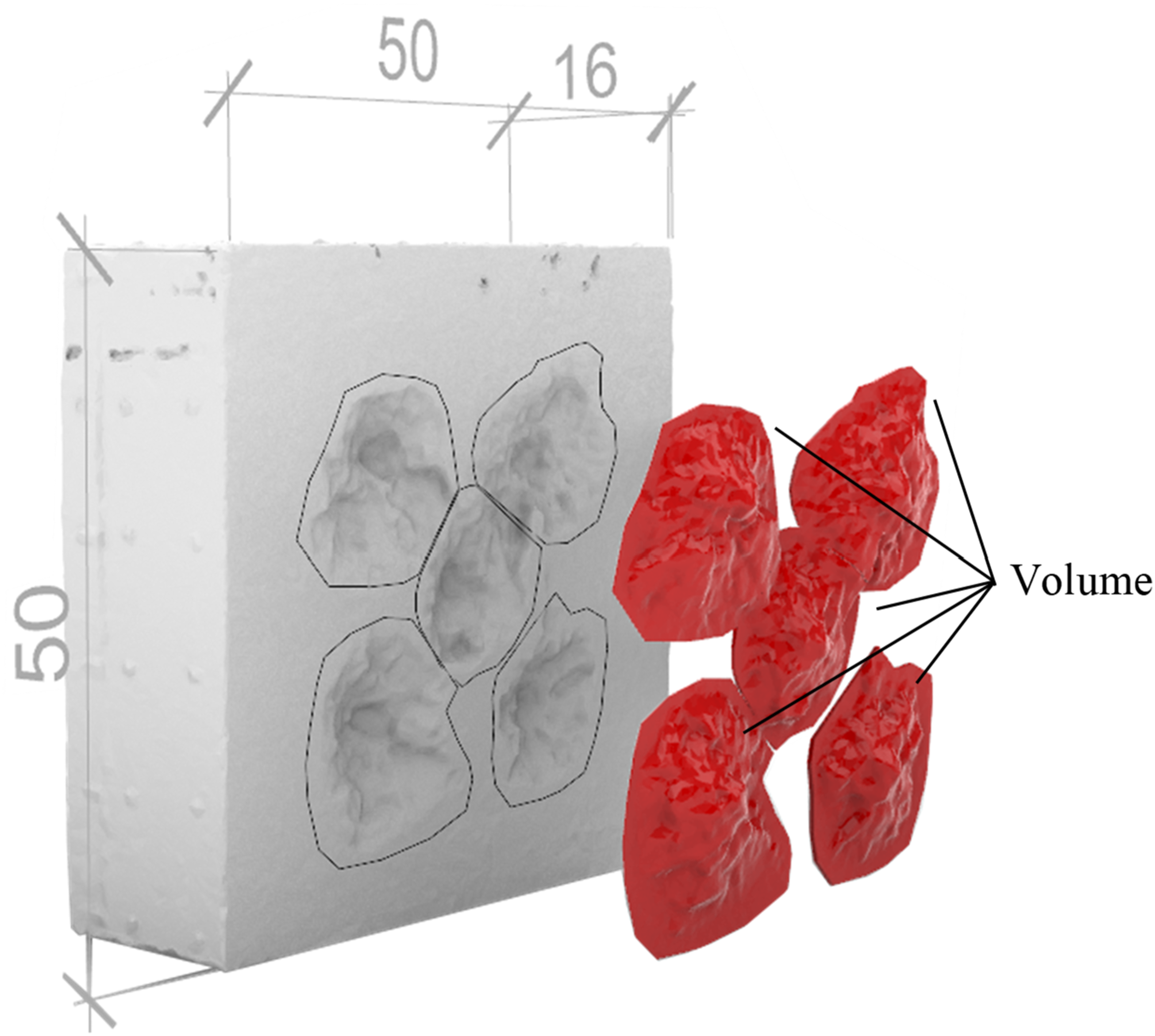
The observed failure modes in both series, U and RU, primarily exhibited crater formation. It appears that the steel rebar reinforcement used in the UHPFRC had a negligible effect, which can be attributed to the dominant role of the UHPFRC in absorbing and redistributing the impact energy. Additionally, it is possible that the strengthening was so significant that the steel rebar reinforcement in the UHPFRC layer was not activated under the arranged loads. For higher loads such as vehicle collision or blast, the steel rebar reinforcement in the UHPFRC could be activated and increase the performance of the strengthening material. Future studies could investigate alternative reinforcement configurations to explore possible variations in failure modes. Fundamental studies on the load-bearing behavior of steel rebar-reinforced UHPFRC under static load (Jungwirth, 2006; Oesterlee, 2010; Leutbecher, 2007) can be utilized for this purpose. Additionally, studies on reinforced UHPFRC under high dynamic loads can used to consider the influence of steel rebar reinforcement, e.g., (Li et al., 2015a; Sherif et al., 2020). There are also investigations on RC-UHPFRC composite elements under impact, which can be beneficial for this consideration (Habel, 2006).
The measured values of the load cells are shown in Figure 7 as a diagram for all five shots using the specimen U-RC-02 as an example. The force curve and the analysis of the crack pattern, which is shown later, can provide information about the wave propagation inside the component. The localized ballistic load causes cracks that prevent the forces from being transmitted to the load cells. This enables to determine the degree of damage of the component on the one hand, and on the other hand the detailed development of the crack propagation. To determine the interaction of the shots, the data can be used. In this study, there is an interaction between the shots. It can be observed that the pre-damage has an influence on the subsequent shot. Forces measured by the load cells on specimen U-RC-02 (colors of the load cells in the pictogram match the force curves. Position of the impact is shown in orange).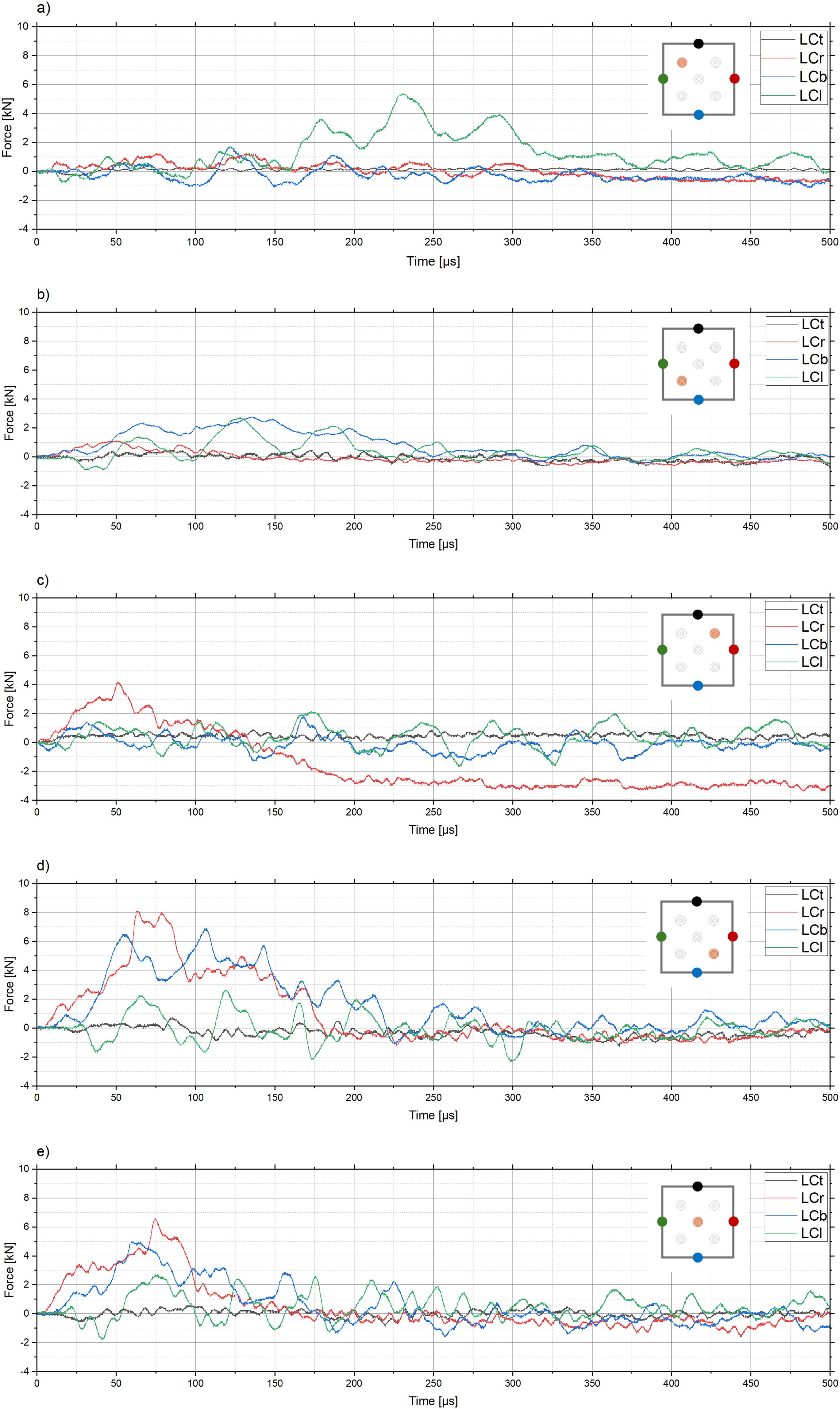
Studies by other researchers have shown that fiber-reinforced concrete layers significantly improve the resistance of reinforced concrete structures against high dynamic loads. It was found that steel fiber concrete layers reduced crater formation on the protective side by up to 95% compared to monolithic reinforced concrete structures (Michal, 2014). As the tests with UHPFRC in this paper were initial tests to explore its potential as a protective layer. The same conditions and parameters as for the two-layered plates of (Michal, 2014) were used for this investigation. The results of this paper are consistent with the basic findings and confirm the effectiveness of UHPFRC in enhancing structural protection against high dynamic loads. Possible interaction effects due to the proximity of the shot points were also included.
In addition to the visual inspection of the surfaces, the internal damage of the test specimens was also visually examined. For this investigation, the specimens U-RC-01, RU-RC-01 and U-RC-03 were cut. Figure 8(d) shows the sectional views of the respective specimens. In the following, the cross-sections have been analyzed and highlighted with colors. The metallic parts of the cross-section are marked in dark blue; the macro-cracks are highlighted in green. Furthermore, digital lines have been added to the cross-section surfaces. The crater is highlighted with light blue and the area with multi-cracks, in cases where it appears, is indicated with red. Internal damage after testing (a) U-RC-01 (5 shots), (b) RU-RC-01 (5 shots), (c) U-RC-03 (8 shots), (d) section lines; light blue: frontal crater, green: cracks; dark blue: reinforcement, red: traction wave/multi-cracks, grey: composite joint failure.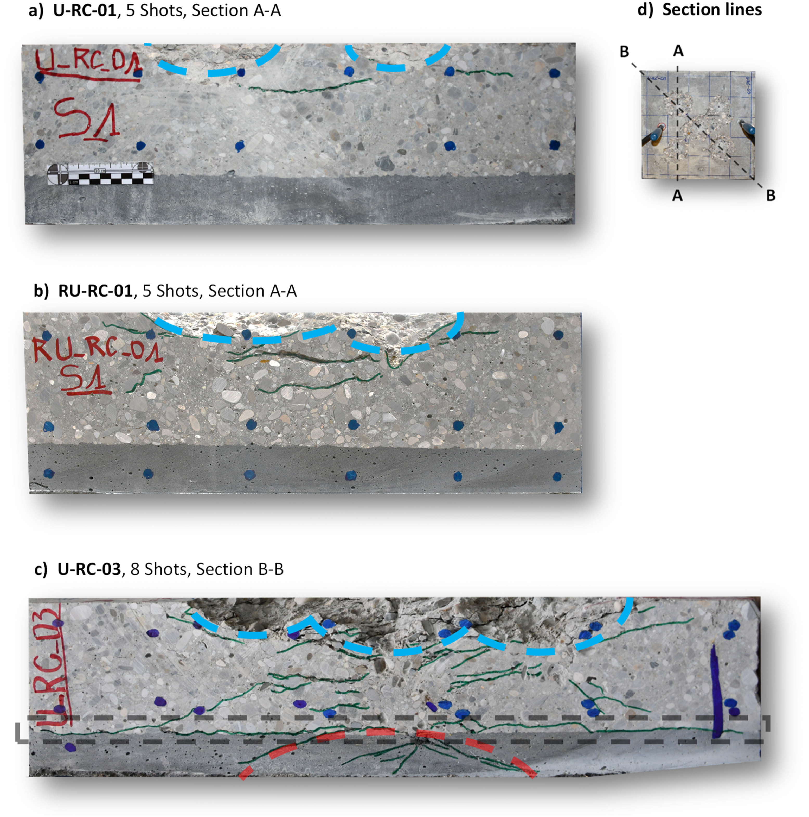
Figure 8(a) shows the cross-section of specimen U-RC-01, and Figure 8(b) illustrates specimen RU-RC-01. For both specimens, the section was cut through positions 1-2, as shown in Figure 8(c); the section line is labeled A-A. The specimens have been loaded with five shots. The crater of the concrete in the reinforced concrete is marked with light blue. The craters caused by the impact are pronounced. Cracks in the normal-strength concrete can be observed around the craters. The visible macro-cracks reach up to 50% of the thickness of the normal-strength concrete. Thus, a softening in this radius around the crater can be assumed. Furthermore, less deep damage to the composite element can be detected. There was no perforation of the test specimen and thus no scabbing. The absorption and transmission of tensile stresses, resulting from the shock wave, by the UHPFRC layer on the protective side, has created a three-dimensional stress state in the NSC. This state leads a higher resistance against penetration of the projectile, thus reducing the depth of penetration and damage. Thus, it can be assumed that the element has a high resistance to impact and a high residual load capacity. This can be excepted because of the breakout of the concrete at the attack side and the area of softened concrete is up to 50% of the cross-section. The residual cross-section assures a certain load-bearing capacity.
The cross-section of specimen U-RC-03 is shown in Figure 8(c). The specimen consists of the reinforced normal concrete base element and a UHPFRC layer without additional steel bar reinforcement. The view of the cross-section corresponds to section line B-B, as shown in Figure 8(c). The cut is through position 1-5-4. The composite element was exposed to the high load with eight shots as described before. For the specimen, the crater on the attack side is also marked with an enveloping light blue line. This crater is larger than the previous one due to the intersection of three loading points. Caused by the multiple loading at position 5 with additional three shots, the projectile pushed into the UHPFRC. The projectile is cut at the height of the composite joint and can thus be seen in the intersecting multi-cracks. The specimen shows significantly more and deeper cracks distributed over the cross-section than specimen RU-RC-01. The visible cracks are distributed over the complete height of the reinforced concrete of the composite element. Apart from in the immediate area of the projectile’s penetration canal in the center of the cross-section, no macro-cracks are visible. The deep cracks in the normal concrete extend at an angle up to the composite joint, where they continue horizontally in the joint. Thus, the UHPFRC layer is delaminated over the whole width of the specimen. From the tip of the projectile pushed into the composite joint, several cracks fan out in the UHPFRC corresponding to the area of the tensile wave marked in red. The cracks are formed across the entire thickness of the cross-section except from a small residual height. The cracks in the UHPFRC are limited to a local area and distributed over the entire width of the specimen. It can be concluded that the increased load resulted in more pronounced damage of the specimen. The projectile that was pushed forward was prevented from perforating by the UHPFRC layer. This was enabled in part by the discontinuity area between the two concretes. Also, the delamination of the top concrete layer dissipated the kinetic energy of the projectile. Dissipation of kinetic energy was achieved by the tensile force absorption in the UHPFRC, crack formation. In addition, the restraint of the normal concrete and the resulting three-dimensional stress state was used, as already described for RU-RC-01. Due to the prevented penetration, scabbing was also eliminated. Despite the more pronounced damage to the component, a residual load-bearing capacity can be assumed due to the determined integrity of the specimen. In particular, the integrity of the inner shell made of UHPFRC makes it possible to prevent break-out of supports on the protective side.
Conclusions and outlook
The test setup and the design of the test specimens have shown to be useful as the effect of the strengthening method with UHPFRC could be demonstrated.
The composite element consisting of reinforced concrete and UHPFRC shows high resistance to high dynamic loads. This can be observed in the fact that none of the test specimens were perforated by the projectile. This is despite the high load of eight shots, which greatly impacted the specimen. In addition, a localized load was induced. According to the result of no perforation, there was no scabbing on the protective side. The behavior can be explained by the absorption and transfer of tensile stresses out of the tensile shaft by the UHPFRC and the resulting three-dimensional stress state in the NSC. This multi-axial state causes higher resistance to the penetration of the projectile, thus reducing the depth of penetration and damage. Also, it can be concluded that the increased loading with eight shots caused more pronounced damage to the test specimen. The projectile was prevented from perforating by the concrete layer. Partly this was enabled by the discontinuity area between the two cementitious materials. The delamination of the overlay also dissipated the kinetic energy of the projectile. Finally, kinetic energy was dissipated by the tensile force absorption in the UHPFRC due to cracking.
The remaining cross-section resulting from undamaged and softened areas allows a certain load-bearing capacity under moderate as well as increased pre-damage.
The involvement of the application of Ultra High Performance Fiber Reinforced Shotcrete (UHPFRSC) is to be carried out, which allows the subsequent addition of thin concrete layers on existing structures resulting in only a minor loss of usable space in the existing structure. The benefits of strengthening free forms and improving fiber effectiveness can also be generated.
With further investigations, an application stage has to be reached, from which guidelines are to be developed so that the load-bearing behavior can be described and the methodology becomes “plannable”.
In addition to experimental investigations using free-fall, impact and detonation tests, FEM simulations are to be carried out and design approaches have to be developed. Furthermore, in the process of the research, non-destructive testing (NDT) and static load tests will be used to determine the damage to the component/structure after the high dynamic load, so that statements can be made about the residual load-bearing capacity based on the existing structure and load.
Footnotes
Acknowledgements
The authors thank the participants of the Institute for Weapons Technology and Materials Science (Prof. Höcherl) of the University of the Armed Forces Munich and the Laboratory for Building Materials (Prof. Dauberschmidt, Prof. Kustermann and Prof. Stengel) of the Munich University of Applied Sciences for providing the laboratory, testing and experimental equipment. We would also like to thank the partner Competence Centre for Material Safety (Graf und Dittmann) for their support in continuing the project.
Declaration of conflicting interests
The author(s) declared no potential conflicts of interest with respect to the research, authorship, and/or publication of this article.
Funding
The author(s) received no financial support for the research, authorship, and/or publication of this article.