
Abstract
Window facades are heavily used in modern design. To ensure that the facade can withstand sufficiently large blast loads, experimental evaluation of the entire facade is crucial. In this study, we present the High Explosive Blast Simulator (HEBSim), an outdoors modular explosive-driven blast simulator with a large cross-section designed for real-size blast testing of glass facades. To evaluate the performance of HEBSim, we performed two test series, one with a rigid steel plate component and one with deformable laminated glass window components. Pressure sensors were used to measure the overpressure histories for both test series and deformation data was gathered using three-dimensional digital image correlation (3D-DIC) for the window component tests. The test series demonstrated that HEBSim generates planar and repeatable blast load profiles in line with explosive pressure resistance (EPR) classifications for various charge masses. In addition, the window component test series illustrated the stochastic fracture behavior of glass. Based on the presented data, HEBSim is found suitable for blast testing of large glass facades.
Keywords
Introduction
On the 22 July 2011, the Norwegian governmental quarter suffered a severe terrorist attack. A vehicle-borne improvised explosive device (VBIED) of ∼950 kg, corresponding to a trinitrotoluene (TNT) equivalent mass of ∼400 kg to 700 kg, was parked at the entry of the tower block housing the Prime Minister’s office and detonated using a homemade detonator (22. juli-kommisjonen, 2012). Eight people lost their lives in the resulting explosion, which also caused major internal and external damage to the governmental quarter as a consequence of the window facades being partly shattered and blown into the buildings. The tower block took the hardest hit where the entire reception and cafeteria were destroyed and severe damage was inflicted on the floors above. The other buildings in the governmental quarter were also damaged and a crater was formed into the underground tunnel system underneath the VBIED.
As a response to the terrorist attack, the Norwegian National Center for Protection of Buildings (NCPB) was established to develop and share knowledge linked to the protection of buildings (Øwre Thorshaug, 2012). Some of the main conclusions from the investigations following the terrorist attack in 2011 were that the allowed distance between the buildings and external vehicles was too small and that severe shattering of the window facades allowed the blast wave to enter the buildings, causing extensive internal damage. For this reason, the improvement of the glass facade’s ability to withstand far-field blast loads became one of the top priorities. To develop improved glass facades, we need to ensure that they can withstand far-field explosions of a certain blast peak overpressure and impulse level. At the same time, care must be taken to ensure that the strength of the facade relative to the building structure remains reasonable. There are multiple standards for testing blast-resistant glazings and windows, covering different aspects and scenarios (Bedon et al., 2014; Larcher et al., 2016, 2017; Lori et al., 2019). Some of the standards are published by the European Committee for Standardization (CEN), including a European standard (EN) for testing security glazings alone (EN 135412, 2012) and a series of standards for testing complete systems like windows, doors and shutters (EN 13123-1, 2001; EN 13123-2, 2004; EN 13124-1, 2001; EN 13124-2, 2004). For instance, EN 13123-2 (2004) provides a classification for the explosion effect restraint of glazing structures, windows and doors (Stolz et al., 2013). The standard defines typical overpressure-time histories for a blast load, resulting in explosive pressure resistance (EPR) domains that should be realized in classification tests with shock tubes and free-field explosions.
The realization of the EPR domains can be achieved in several ways. One option is to use free-field explosions, see (Payne et al., 2016), where a large high explosive (HE) is placed on an arena test field to generate the blast wave. However, there are several downsides to free-field explosion tests. They are typically very costly, time-consuming, hard to reproduce, weather dependent, require a large crew, produce imprecise data and come with an increased risk of accidents during storage, transport and setup of the HE. In addition, for far-field blast loads, the sub-structure supporting any test object has to be tall and wide to prevent clearing effects of the incoming blast wave (Rigby et al., 2012). An alternative to free-field explosion tests is to simulate the blast load with a shock tube, also known as a blast simulator. The main objective of a blast simulator is to replicate the behavior of a free-field explosion, including all time-variant gas-dynamic conditions (Ritzel, 2007).
Blast simulators are typically categorized as either pressure- or explosive-driven. Pressure-driven blast simulators (Andreotti et al., 2015; Aune et al., 2016; Colombo et al., 2011; LeBlanc et al., 2007; Lloyd et al., 2011) generate the blast wave by constructing a large pressure difference between a high-pressure section, namely the driver section, and a low-pressure section, referred to as the driven section. The driver and driven sections are typically separated by a suitable number of diaphragms, which are ruptured to initiate the blast wave. Some blast simulators have multiple operation modes, like the Australian National Facility of Physical Blast Simulation (NFPBS) (Gan et al., 2020, 2024; Remennikov et al., 2018, 2019) based on the patented Advanced Blast Simulator (ABS) (Ritzel and Parks, 2015). The NFPBS can be loaded either by using conventional compressed gas (CG) with diaphragms or by using a gaseous detonation (GD). The CG mode allows for a more pronounced and adjustable negative phase with a corresponding strong secondary shock wave, while the GD mode results in a stronger shock wave with a weak negative phase. Pressure-driven blast simulators typically provide repeatable blast waves, at the cost of long preparation times. In explosive-driven blast simulators (Atoui et al., 2022; Ritzel, 2007; Stewart, 2018, 2019; Stewart and Pecora, 2015), the blast wave is generated by detonating an explosive. By altering the mass, geometry, position and type of explosive, a variety of blast waves can be accomplished. Hence, explosive-driven blast simulators provide increased flexibility compared to the pressure-driven. In addition, the rigging process of explosive-driven blast simulators is fast, facilitating efficient test series.
In this paper, we present the blast simulator of the NCPB, named the High Explosive Blast Simulator (HEBSim). HEBSim is an outdoors modular explosive-driven blast simulator with a large cross-section. It is designed for blast testing of large components in a repeatable and efficient manner with the possibility to measure the component deformations using three-dimensional digital image correlation (3D-DIC). First, we describe the details of the blast simulator including the different modules and design choices. Second, to illustrate the performance of HEBSim, we present a variety of blast load profiles generated with the blast simulator using a rigid steel plate target component. Third, we present a test series on laminated glass window components with acquired deformation histories.
HEBSim
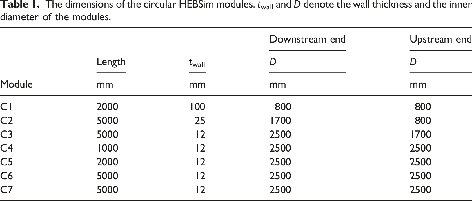
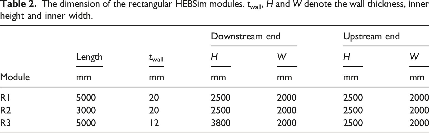
HEBSim is a modular explosive-driven blast simulator, designed to generate free-field blast loads as described in EN 13124-1 (2001) with high repeatability. Being modular, the length of HEBSim can vary, with a current longest configuration of 38 m. It consists of a total of 10 modules made of structural steel, where the modules can be joined in bolted connections. Figure 1 provides an outline of HEBSim with all modules. The corresponding dimensions of each module are given in Tables 1 and 2. Along the length from the detonation chamber C1 to the downstream end R3, HEBSim consists of seven circular modules C1–C7 and three rectangular modules R1–R3. The inner diameter of the circular modules varies from 800 mm to 2500 mm, while the rectangular parts are 2000 mm wide with heights in the range of 2500 mm to 3800 mm. Each module is simply supported on a railway carriage which can move freely along tracks on the ground. Test components can be mounted in all bolted connections between the modules. However, they are typically mounted at the downstream end of the rectangular cross-section modules R1, R2 and R3. Overview of HEBSim with all rectangular (RX) and circular (CX) cross-section modules. The dimensions of the circular HEBSim modules. twall and D denote the wall thickness and the inner diameter of the modules. The dimension of the rectangular HEBSim modules. twall, H and W denote the wall thickness, inner height and inner width.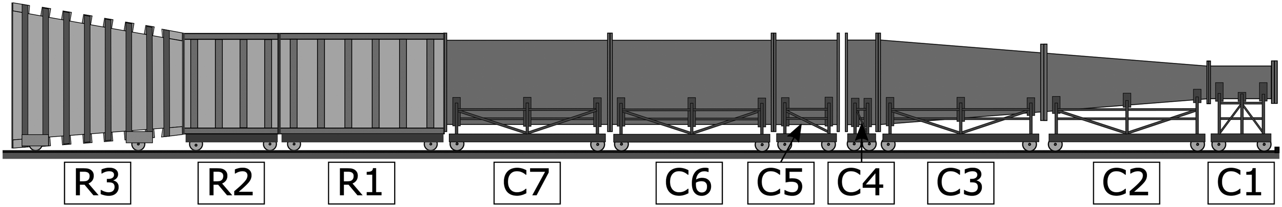
To generate the blast load, an explosive charge is placed in the detonation chamber, denoted C1 in Figure 1. As the charge is detonated, a shock wave immediately starts to propagate downstream HEBSim, while internal reflections with the inner chamber walls create multiple consecutive shock waves. In addition, one portion of the shock waves is vented out of the circular hole at the back end plate mounted to the detonation chamber, presented in Figure 2(c). The mass, geometry, position and type of explosive combined with the mounted end plate and the length of the connected modules are important factors controlling the generated blast load profiles at the downstream end of HEBSim. Illustration of the detonation chamber module C1 seen from a downstream (a), side (b) and upstream (c) perspective using an end plate with a 400 mm venting hole.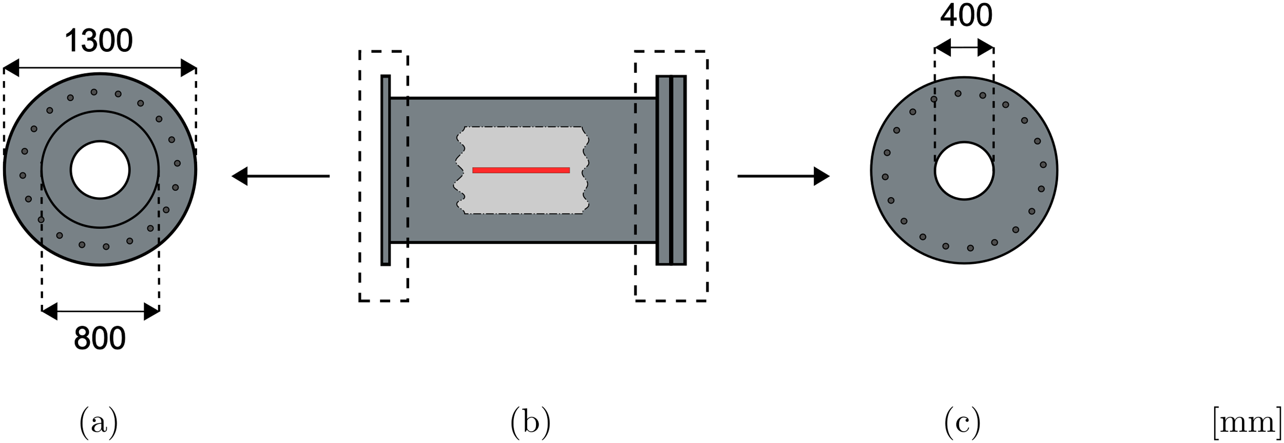
As the shock wave leaves the detonation chamber, it propagates through the two cone-like modules, C2 and C3, illustrated in Figure 3. These two modules are used to gradually expand the diameter of the circular cross-section from 800 mm in the detonation chamber C1, to 2500 mm in the circular modules C4, C5, C6 and C7, see Figure 4(b). The diameter expands with a constant inclination angle over a total length of 10 m. The three first modules, C1, C2, and C3, represent a non-uniform and complicated flow pattern for the propagating shock wave. Due to the combined length of the constant circular modules C4, C5, C6 and C7, the shock wave will have a more uniformly shaped front at the downstream end of module C7. Cone-like modules C3 (a) and C2 (b) with expanding diameter. Illustration of the HEBSim modules with constant cross-sections. The rectangular modules are represented by module R1 (a) and the circular are represented by modules C6 and C7 (b).

When a test component is mounted between two modules, it acts as an enclosement reflecting the shock wave back towards the detonation chamber. Depending on the end plate of the detonation chamber, the shock will move back and forth between the detonation chamber and the test component with decreasing intensity, leading to multiple shock reflections on the blast-exposed surface of the test component. To further control the blast intensity reduction of the sequential reflections, a venting gap is constructed between modules C4 and C5. This type of venting technique is similar to what is used in the NFPBS (Gan et al., 2020, 2024; Remennikov et al., 2018, 2019). The venting effect on the sequential reflections can also be amplified by increasing the hole diameter in the end plate of the detonation chamber, see Figure 2(c). In addition, the venting eliminates the forming of a quasi-static overpressure inside HEBSim after a test.
The modules with constant rectangular cross-sections, R1 and R2, see Figure 4(a), allow test components up to 2000 mm wide and 2500 mm tall. With the expanding rectangular cross-section module, R3, the test component can be even taller, up to 3800 mm. However, the transition from a circular cross-section to a rectangular cross-section (C7 to R1) comes at a cost. The rectangular module widths are narrower than the diameter of the circular modules and gaps are introduced in the transition corners, see Figure 5. This results in a discontinuous transition between modules C7 and R1 which disturbs the uniform shock wave propagation, resulting in a more turbulent shock wave impacting the mounted test component. A possible remedy to reduce the turbulence generated from the transition is mentioned in the discussion. In addition, the shock wave is vented to some extent by the corner gaps, which might reduce its intensity. If module R3 is used, more disturbances are added with the expanding height that introduces a slight curvature in the shock wave. For the remainder of this paper, we will focus on a configuration where the test components are mounted at the downstream end of module R1. Transition between the circular module C7 and the rectangular module R1 illustrated with a downstream perspective behind the detonation chamber including all circular modules (a), with a downstream perspective including only modules C7 and R1 (b) and an image with an upstream perspective from the inside of module R1 (c).
Instrumentation
HEBSim is instrumented with Kulite XT-190 (Kulite, 2024) pressure sensors to measure the overpressure histories inside the modules, sampled at a rate of 500 kHz. The locations of the sensors vary based on the configuration. However, the sensors PI1 and PI2, shown in Figure 6 are present in all the experiments. The two sensors are placed 1500 mm and 2500 mm upstream of the downstream end of the C7 module, and measure the incoming and reflected incident overpressure along the module wall. In this study, where all test components are located at the downstream end of the R1 module, we use PI1 and PI2 to evaluate the repeatability of the incident overpressure generated by the shock wave. The HEBSim setup for the rigid steel plate experiments (a) with a zoomed-in top view illustration of the C7 and R1 modules (b).
Type of HE material
Overview of the charge stack configurations. The detonation point is marked with a red dot.
Electric detonator (a) and a pre-fabricated tube of Magnasplit explosive (b).
Blast load
To evaluate the characteristics of the blast loading generated using HEBSim, a rigid steel plate with seven pressure sensors was mounted to the downstream end of module R1. Multiple different charge masses were used to generate a variety of blast load intensities on the blast-exposed area of the rigid steel plate. The resulting measurements are used to evaluate the repeatability and planarity of the shock wave impacting the test object and relate the applied blast load intensities to the EPR levels of EN 13124-1 (2001).
Setup
Blast loading characteristics for all 20 blast experiments presented in terms of averaged values
To evaluate the blast load acting on the rigid steel plate, seven pressure sensors were placed along the blast-exposed area with positions and names indicated in Figure 8. The positions of the seven pressure sensors were defined to evaluate potential spatial and temporal variations in the reflected overpressure histories along the blast-exposed component surface. We assume that the incoming blast wave is double-symmetric with the current sensor configuration. Further, the incoming and reflected incident overpressure histories were measured at the two pressure sensors, PI1 and PI2, located along the inner wall of module C7, as indicated in Figure 6. Illustration of the rigid steel plate used to evaluate the reflected blast load characteristics with sensor names (a) and locations (b). Sensor PC3 is located at the center of the plate.
Blast load profiles
Figures 9 and 10 and Table 4 present the blast load profiles obtained from the 20 blast experiments using the rigid steel plate. Figure 9 shows the measured reflected overpressure and impulse for all seven steel plate sensors, PC1–PC7, and the average of the sensors, The reflected overpressure and impulse history measured from a 600 g Magnasplit charge for all the rigid steel plate sensors, PC1-PC7, (a, c, e) and the corresponding average, The incident overpressure measured from sensor PI1 (a) and the respective reflected overpressure measured from the center sensor PC3 (b) for two iterations per charge from charges 350 g, 500 g and 700 g. The second iteration of each charge is plotted with a black dotted line. The time axis is relative to the time of arrival at the center sensor PC3 for each experiment.

Figure 10 presents the incident overpressure measured from sensor PI1 and the respective reflected overpressure measured from the center sensor PC3 for two iterations per charge from charge masses of 350 g, 500 g and 700 g. The second iteration of each charge is plotted with a black dotted line. The time axis is relative to the time of arrival at the center sensor PC3 for each experiment. From Figure 10(a) we see varying times of arrival for the incident overpressures of the different charges, indicating a difference in blast wave propagation speed. The 350 g charge exhibits the lowest peak overpressure in both the incident and reflected case. The peak overpressure values and the slope of the overpressures increase with increasing charge masses. However, the negative phases of the experiments, that is, the part of the overpressure history where the overpressure is negative, seem to be similar.
The compilation of experiments and accompanied empirical relations presented by Kingery and Bulmash (Kingery and Bulmash, 1984) for hemispherical charges serve as a well-known reference in the domain of blast loading. Figure 11(a) presents the averaged reflected experimental overpressure curves, 
The averaged reflected overpressure,
Estimated Friedlander parameters Pr, max, b and
EPR classification from EN 13124-1 (2001). The positive phase duration
The peak reflected overpressure, Pr, max, and the positive reflected impulse,
Component tests
To investigate the performance of HEBSim on deformable components, the rigid steel plate was replaced by deformable single laminated glass windows, mounted to a rigid steel plate with a square open section using a rigid steel frame. Here, the objective is to illustrate and evaluate the ability to measure the out-of-plane displacement and fracture history of the laminated glass windows during blast loading.
Laminated glass windows
The tested windows consisted of two layers of glass bonded together by a polyvinyl butyral (PVB) interlayer. When exposed to extreme loading, laminate glass components like these typically fail in five distinct stages as presented in Figure 13 (Larcher et al., 2012; Rudshaug et al., 2023). Before fracture, the glass layers experience small elastic deformations followed by a stochastic and brittle fracture response, marking the transitions from stage 1 to 2 and stage 2 to 3 in Figure 13. However, from stage 3 most of the glass fragments will still be glued onto the PVB interlayer, resulting in a glass-reinforced polymer component. This enables the layered component to undergo large deformations in stage 3 and 4 before a global fracture occurs in stage 5, where the PVB interlayer fractures. Typical failure stages of laminated glass, adapted from (Rudshaug et al., 2023).
Setup
A total of four quadratic single laminated glass windows with dimensions 1220 × 1220 mm were tested, consisting of two 4 mm thick glass plates bonded by a standard 1.52 mm thick PVB interlayer. As presented in Figure 14, the windows were mounted to the rigid steel plate with a square open section using a rigid steel frame, a setup in close resemblance with the one described in EN 135412 (2012). The windows were centered in the rectangular cross-section at the downstream end of module R1. A Magnasplit charge of 200 g, see Table 3, located in the center of the detonation chamber C1 was used to generate the blast loading for each test. The tests were performed on a dry spring day with temperatures in the range 6.5°C to 10°C. The rigid steel plate with a square open section and two pressure sensors PG1 and PG2 (a), the rigid steel plate with a mounted window including optical markers S1–S5 (b) and a section view illustrating the window mounting (c). The optical markers are placed in a sparse grid-like manner with horizontal and vertical distances of 230 mm where S1 is located at the center of the window.
To measure the displacement histories of the windows, we mounted two Phantom v2012 high-speed cameras (Adept, 2022) in custom steel cages on the side walls of module R2, see Figure 15(b). The high-speed cameras were placed in a stereo-vision configuration and set up to record at a sampling rate of 22 626 fps at 1200 × 800 pixels. A set of optical markers with a diameter of 40 mm was attached to each window at specific locations to measure the displacement histories using 3D-DIC. To calculate the displacement histories of the optical markers from the high-speed camera recordings we used the 3D-DIC software eCorr (Fagerholt, 2008). Figure 16 shows the mounted window with the optical markers and an image of the calibration target. Three images of the calibration target at different positions were taken to correlate the camera positions in the stereo-vision setup. The cameras were triggered by the incoming shock wave in sensor PG1, see Figure 14(a). To correct for camera vibrations, an optical marker was mounted to the inner wall of module R2, see Figure 16(a). The measured vibrations from the correction optical marker were subtracted from the component displacements to correct the measurements. Furthermore, the pressure sensors and the high-speed cameras operated at different sampling rates. To synchronize them, we used the arrival of the blast wave at sensor PG1 to denote t = 0 for the corresponding measurements. The HEBSim setup for the laminated glass window experiments (a), and zoomed-in top view image of the three last modules (b). The mounted window with optical markers (a) and an image of the calibration target from the 3D-DIC calibration process (b). The optical marker used to correct for vibrations is marked with a red circle in (a).
Results
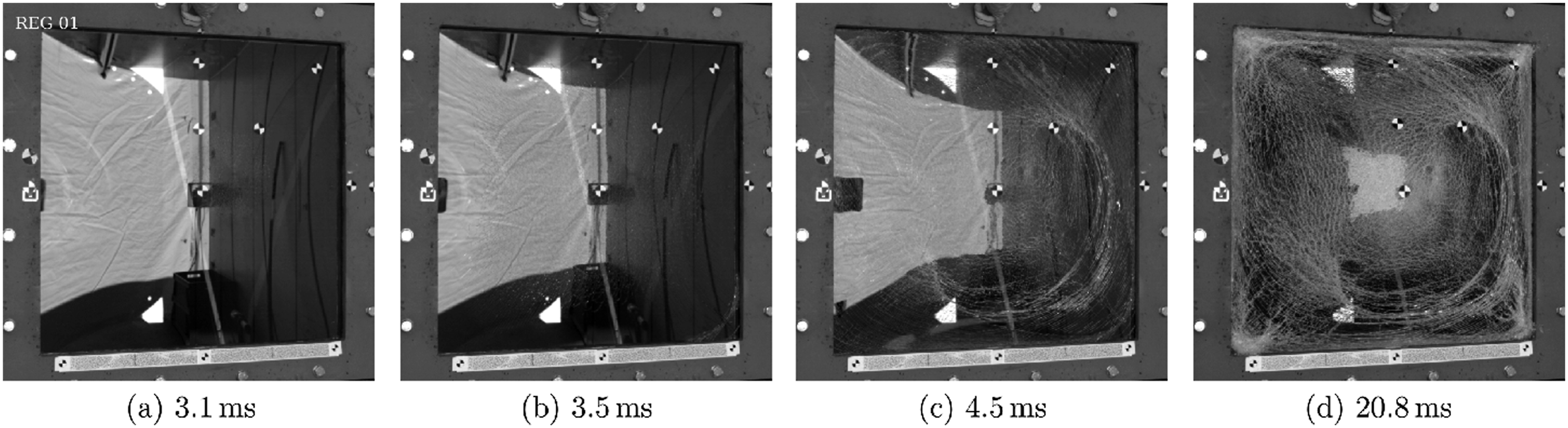
Figure 17 presents the measured overpressure and displacement history of the first window test. The window is exposed to a peak overpressure of ∼60 kPa and exhibits a maximum displacement of ∼190 mm at the mid-point (S1). In Figure 17(b), we note that fracture initiates and propagates ∼3 ms to 5 ms after the shock wave arrives. At the maximum displacement, ∼20 ms, the glass layers are completely fractured, and the component acts as a glass-reinforced polymer, as illustrated in stages 3 and 4 in Figure 13. The window remained in the rigid steel frame for the entire test. High-speed images from the test are presented in Figure 18. In Figure 18(a), fracture has initiated in the first glass layer. Later, fracture also initiates in the second layer and the fracture patterns expand in Figure 18(b) and (c) towards the window edges. Finally, the resulting dense fracture pattern is seen in Figure 18(d). The average reflected overpressure, High-speed images showing the laminated glass window from Test 1 at key stages in the cracking process.
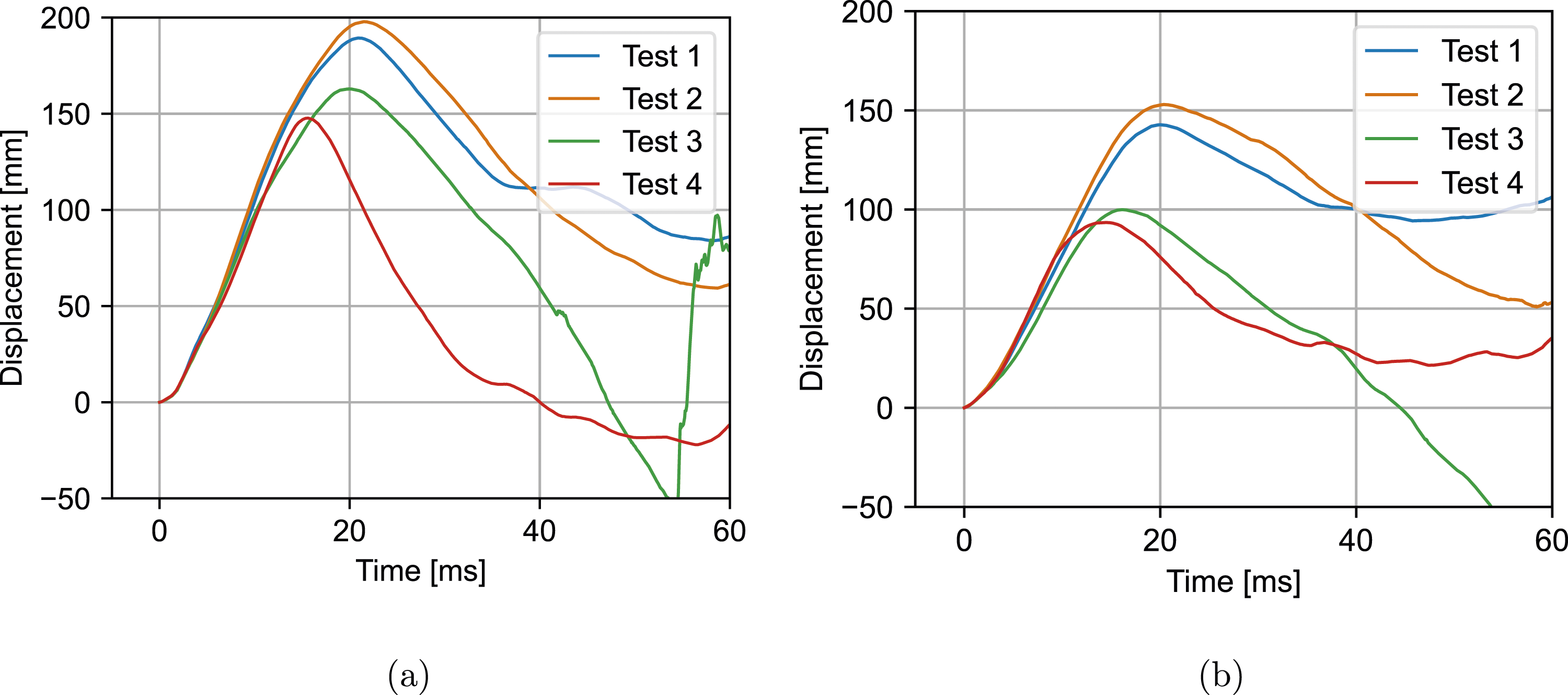
The overpressure and displacement history of all four window tests are presented in Figures 19 and 20. Figure 19(a) compares the reflected overpressure histories measured from sensor PG1 for the window tests to the corresponding 200 g rigid steel plate test measurements from sensor PC1, while Figure 19(b) compares the incident overpressure histories from sensor PI1, where both the downstream and reflected upstream incident overpressure peaks are present. To summarize, the overpressure history from the rigid steel plate test is in good agreement with the measured overpressure histories from the window tests for the respective sensors. Figure 20 shows the displacement histories measured for optical markers S1 and S3 for all four tests. We note that all the tests follow a similar displacement history up to fracture initiation. After this point, the displacement histories vary for each test. The mid-point optical marker S1 exhibits a larger maximum displacement than optical marker S3. The reflected overpressure histories measured from sensor PG1 compared to the corresponding rigid steel plate measurements from sensor PC1 for the 200 g charge (a) and the incident overpressures histories measured from sensor PI1 in the glass tests compared to the same measurement for the corresponding 200 g rigid steel plate test (b). Displacement histories for subsets S1 (a) and S3 (b) from all window component tests.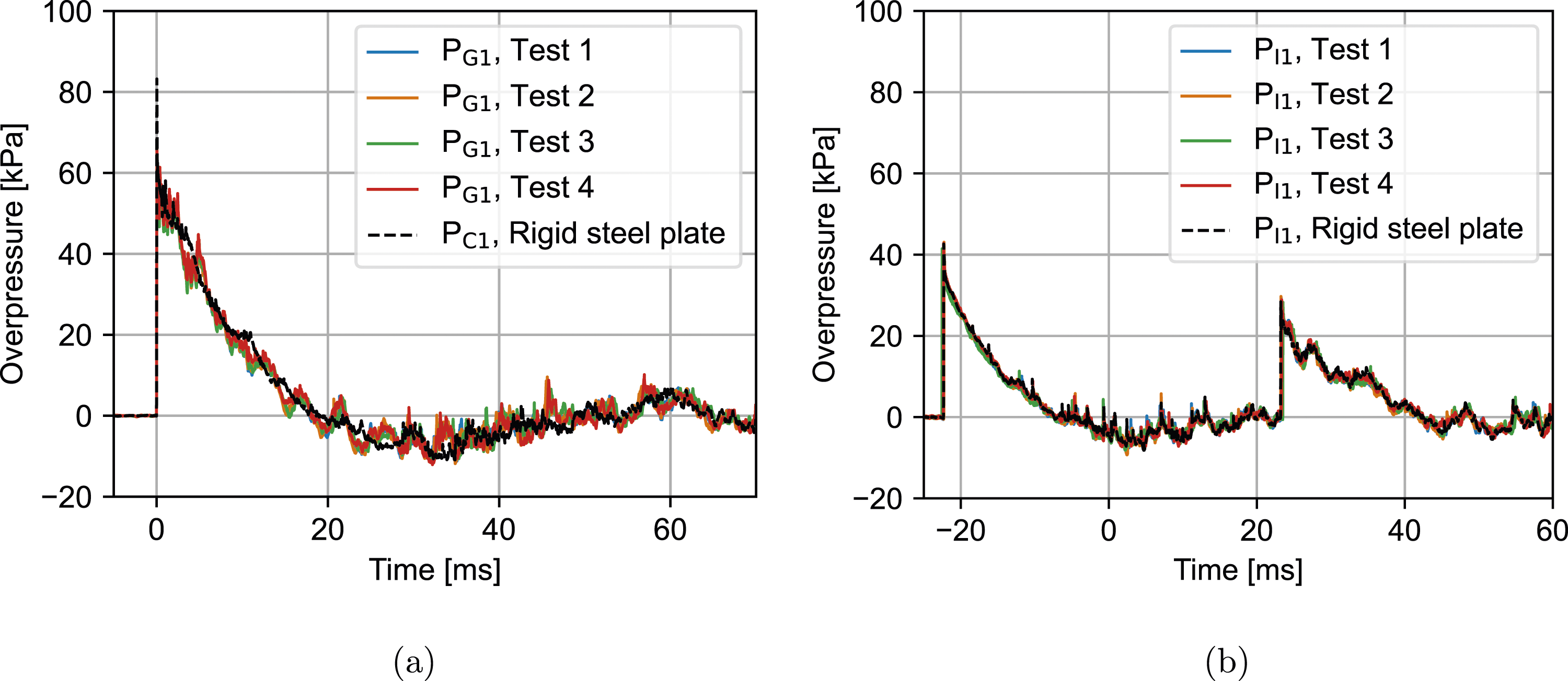
Discussion
Based on the load profiles generated with the rigid steel plate in Figures 9 and 10 and Table 4, the shock waves produced with HEBSim can be considered both planar and repeatable. Figure 9 and Table 4 illustrate the planarity of the shock wave, with a maximum variation in time of arrival of ∼0.07 ms. Given the turbulent disturbances introduced by the sudden transition from the circular module C7 to the rectangular module R1 shown in Figure 5, combined with the large cross-section, the variation in time of arrival is sufficiently small to consider the shock wave as planar. When investigating the maximum deviations in peak reflective overpressure, Pr, max, in Table 4, we note that the relative deviation seems to decrease with increasing charge mass. This trend may stem from an increasing number of transverse shock wave reflections during the longitudinal shock propagation for the larger charges, homogenizing the shock wave properties across the cross-section. Regarding the repeatability of the generated blast load profiles, Table 4 and Figures 12 and 19 indicate good repeatability both in terms of repeated charge masses and variable test components.
The large cross-section of HEBSim makes the blast simulator suitable for full-size facade component testing. By mounting an entire facade element including supports we can assess the component interdependencies resulting in the overall global facade component behavior. To allow mounting of large facade elements, HEBSim can be extended using the rectangular modules R1, R2 and R3. As mentioned, the current design does not include a smooth transition between the circular and rectangular cross sections. For this reason, we introduce some unwanted turbulent disturbances. Adding a smooth transition would be beneficial for future studies to produce a smoother shock wave.
Being an explosive-driven blast simulator, HEBSim provides the flexibility of altering the generation of the shock wave in terms of the explosive type, geometry, mass and location. In this study, we chose to use the civilian explosive Magnasplit which is typically used in tunneling applications. However, we also considered using the military-grade explosive C-4 which has a higher amount of detonation energy and a higher detonation velocity, and hence a larger relative equivalent mass in TNT than Magnasplit. Another important difference between the two explosives is the oxygen balance. C-4 is known to have a negative oxygen balance (Meyer et al., 2007), while Magnasplit has a positive oxygen balance (Orica, 2024). From initial testing, it was found that C-4 resulted in a stronger light flash during the detonation which makes for instance filming with high-speed cameras through glass more challenging. It was also assumed that the lower detonation velocity in Magnasplit could reduce the wear on the HEBSim modules.
HEBSim is located outdoors, which has several advantages. For instance, it facilitates health, safety and environment (HSE) measures in operation and rigging, removes any restrictions on operation machines and widens the range of future expansions or modifications. However, the outdoor placement makes HEBSim exposed to variations in temperature and moisture, which may impact the generation of the shock wave in terms of the detonation process of the explosive and the blast wave propagation. For this reason, it is important to measure the temperature and moisture level and ensure stable weather conditions when performing the experiments.
When comparing the overpressure and impulse curves generated in HEBSim to empirical curves, see Figure 11, we note that HEBSim can capture the positive phase accurately. The negative phase is underestimated compared to the cubic approximation presented in (Rigby et al., 2014). The underestimation indicates that we are not able to represent the negative phase of a hemispherical far-field blast explosion with the current HEBSim configuration. Further studies are needed to investigate the underestimated negative phase. Furthermore, the underestimation in the negative phase may result in a reduced pull-back motion for the facade elements. By investigating the displacement histories of the optical markers attached to the window in Figure 20, the pull-back motion is still significant. However, the stochastic fracture behavior of glass makes it hard to quantify this effect. The fracture evolution of Test 4 in Figure 20 resulted in a pull-back motion, while for instance in Test 1 it did not.
The generated blast load profiles discussed in this paper are based on the presented HEBSim configuration using a venting gap between modules C4 and C5 of 200 mm and a 400 mm venting hole in the end plate of the detonation chamber module C1. By varying the size of the venting gap and venting hole we can alter the properties of the generated blast load profiles. For instance, using an end plate without a venting hole will increase the peak overpressure Pr, max and removing the end plate will reduce Pr, max. We also limit the charge mass to 700 g in this study, reaching an EPR level of 2. For the current range of charge masses, we see a clear linear trend in the overpressure-impulse plot presented in Figure 12. In future studies, it would be interesting to test larger charge masses reaching up to EPR 4 and evaluate if the overpressure-impulse trend continues linearly.
Conclusions
In this paper, we presented HEBSim, an outdoor modular explosive-driven blast simulator with a large cross-section. Through two test series, one with a rigid steel plate component and one with deformable laminated glass window components, we illustrated the performance of HEBSim through pressure and deformation measurements. The rigid steel plate test series showed that HEBSim generates planar and repeatable load profiles in line with EPR classifications for a variety of charge masses, making it applicable in the design of glass facades. The glass window test series demonstrated the applicability of using 3D-DIC to extract component deformations for experiments performed in HEBSim, enabling the extraction of valuable data for use in future research.
Footnotes
Acknowledgements
The authors would like to thank Mr Knut Ove Hauge and Mr Daniel Dobrev Gildestad for assisting with the experiments.
Author contribution
Declaration of conflicting interests
The author(s) declared no potential conflicts of interest with respect to the research, authorship, and/or publication of this article.
Funding
The author(s) disclosed receipt of the following financial support for the research, authorship, and/or publication of this article: The present work has been carried out with financial support from the Norwegian Defence Estates Agency (NDEA). This research received no specific grant from any funding agency in the public, commercial, or not-for-profit sectors.