
Abstract
Impact and blast wave loadings act as high instant energy and might cause damage to reinforced concrete infrastructures. This research aims to investigate the effect of using different length proportions of carbon fiber on the mechanical behaviors of concrete. Moreover, in this study, original carbon fiber and sizing-removed carbon fiber were added into concrete with different mix-proportions. The sizing on the carbon fiber surface was removed by using heat-treated method. In addition, the carbon fiber was dispersed by a high-pressure air compressor. Lengths of 12 mm and 24 mm carbon fibers were used in different mix-proportions to find the highest mechanical strength of carbon fiber reinforced concrete (CFRC) under a 1% fiber-to-cement weight ratio. Compressive, flexural, and impact tests were conducted on CFRC specimens. The CFRC specimen with 50% 12 mm and 50% 24 mm sizing-removed carbon fiber attained the highest impact resistance, and it also had the best performance under blast wave loading compared with the other CFRC specimens. The broken CFRC specimens were examined by an optical microscope to identify the failure mode of the carbon fibers in CFRC specimens. The addition of 50% 12 mm and 50% 24 mm sizing-removed carbon fiber can significantly improve the compressive and flexural strength of reinforced concrete.
Highlights
• Sizing removed process on the surface of carbon fiber. • Pneumatic method for fiber dispersion. • CFRC specimens with different lengths of fiber and their distributions. • Static, impact, and blast wave behaviors of CFRC specimens with different fiber lengths and mix-proportions. • The broken surface analysis of CFRC and the surface morphology of carbon fiber.
Introduction
Reinforced concrete structures are prone to cracks, damage, and spalling when subjected to external loadings or harsh conditions. The impact and blast wave loadings act as high instantaneous energy that could cause catastrophic damage to reinforced concrete structures (Konrád and Sovják, 2019; Zhang et al., 2022). Fiber reinforced concrete (FRC) has been widely used to repair and strengthen reinforced concrete infrastructures in the last few decades. FRC applications are employed in concrete pavement such as aircraft runways, dam spillways, highway bridge expansion joints, tunnels, and harbor wharves, and FRC can also be applied to chemical factories and military reinforced concrete structures (Sherif et al., 2020).
Predecessor’s research on FRC particularly emphasized on types of fiber, compressive strength, flexural strength, impact resistance, fiber dispersion, and sizing removal process. Generally, adding natural and artificial fibers into reinforced concrete could reduce shrinkage and increase the stiffness and toughness of the concrete (Beppu et al., 2022; Bheel et al., 2020). Some natural fibers, such as coconut, flax, hemp, jute, sisal, and linen, were integrated with reinforced concrete, and they performed well under static and impact loadings (Ahmed, 2013; Badagliacco et al., 2020; Chen and Chouw, 2018; Juradin et al., 2021; Page et al., 2021; Palanisamy and Ramasamy, 2020; Ramakrishna and Sundararajan, 2005; Sathish et al., 2020; Thomas and Jose, 2022; Wang and Chouw, 2017).
Artificial fiber reinforced composites like polyethylene terephthalate waste bottles fiber and steel fiber can increase ductility and impact resistance of FRC (Gupta et al., 2015; Nili and Afroughsabet, 2010; Saxena et al., 2018). The influence of polypropylene fiber on the strain of recycled aggregate concrete was higher when compared with standard concrete. The compressive strength was increased by the replacement of recycled aggregate with 0.6% polypropylene fiber (Ahmed et al., 2020; Das et al., 2018). The mechanical strength of basalt fiber reinforced concrete (BFRC) specimens was influenced by the sizing on surface of the basalt fiber. The BFRC with sizing-removed basalt fiber obtained higher mechanical performance than the BFRC with original basalt fiber (Li et al., 2022b). Moreover, the mechanical strength of BFRC specimens was also influenced by the length of basalt fiber. Kabay (2014) showed that basalt fiber can improve the flexural strength, compressive strength, impact resistance, and also abrasion resistance of concrete. Aramid fiber is light weight material that has high tensile strength, and adding aramid fibers into FRC could enhance the mechanical performance of FRC material (Li et al., 2022a).
Steel fiber reinforced self-compacting concrete improves the post-cracking flexural resistance and increases energy absorption. The durability of the steel fiber reinforced concrete was increased by increasing fractions from 0% to 1.5%, but it decreased slightly as the volume fractions increased from 1.5% to 2.0% (Frazão et al., 2015; Gao et al., 2020). To prolong the service life of reinforced concrete structures, ultra-high performance steel fiber reinforced concrete was proposed to enhance their ductility and toughness (Ferrara, 2019; Ridha et al., 2017). Adding pozzolanic materials and acrylic polymer can improve the workability and reduce water absorption of glass fiber reinforced concrete (Kabay and Amed, 2020).
Carbon fiber is a light weight material that has high tensile strength, and it is resistant to corrosion. Nowadays, carbon fiber applications are utilized in the automotive industry, aerospace or aircraft industry, sports equipment, wind turbine blade, and as well as in reinforced concrete infrastructures. Fluidity characteristics are reduced by increasing the length of carbon fiber from recycled carbon fiber reinforced polymer (CFRP) in concrete (Li et al., 2021a; Mastali et al., 2017). With sizing on the surface of carbon fiber removed by physical and chemical approaches, the compressive strength of the carbon fiber reinforced concrete (CFRC) specimen could increase by 14% compared with CFRC specimen with original carbon fiber (Li et al., 2019). Furthermore, both original and recycled carbon fiber could enhance their flexural strength, compressive strength, and impact resistance under different weight proportions (Li et al., 2021a). The carbon fibers were dispersed under the nozzle technique with hydroxyethyl cellulose, the dispersing agent polycarboxylate-type superplasticizer, and silica fume. The distributions were uniform in the cement-based composites. In addition, threshold components were calculated by using the optical microscope and the degree of dispersion was compared by mathematical calculation (Hambach et al., 2016; Kim et al., 2018; Wang et al., 2008, 2014). Fiber length could affect the mechanical properties of CFRC. Previous study had shown that the impact resistance and flexural strength of CFRC were increased by increasing the length of the fibers, and the compressive strength was increased by decreasing the fiber length (Li et al., 2021b).
The hybrid fiber reinforced concrete (HFRC) improves the static and dynamic behavior compared with single fiber reinforced concrete. The hybrid fibers include polypropylene, steel, glass, cellulose, carbon, aramid, and sisal fibers; and they can increase the energy absorption capacity to enhance impact resistances under different water-cement ratios and volume/weight fractions (Asrani et al., 2019; Bankir and Sevim, 2020; Deng et al., 2020; Ding et al., 2017; Fakharifar et al., 2014; Lee et al., 2017; Li et al., 2021c; Naraganti et al., 2019; Rahmani et al., 2012; Shi et al., 2020; Yuan and Jia, 2021).
In this study, lengths of 12 mm and 24 mm carbon fibers were used in different mix-proportions to find the highest mechanical strengths of the CFRC under a 1% fiber-to-cement weight ratio. Besides using different lengths of carbon fibers, the tests were conducted on using mix-proportions of fiber lengths with original and sizing-removed fibers. The compressive strength, flexural strength, and impact resistance of different mix-proportions CFRC specimens were obtained. Furthermore, the blast wave was tested to verify the anti-blast wave performance of CFRC.
Materials
The applications of carbon fiber can be seen in aerospace industry, automotive parts, sports equipment, and civil engineering for its high specific strength. Carbon fiber can increase the strength of structural integrity under static and dynamic mechanical performances. The carbon fiber properties, sizing removal process, and CFRC specimen preparation are introduced in the following subsections.
Carbon fiber
The polyacrylonitrile (PAN) based carbon fibers were obtained from Tairylan Division, Formosa Plastics Group. The PAN-based carbon fiber has 4900 MPa tensile strength, 250 GPa tensile modulus, 2.0% elongation, 1.81 g/cm3 density, and a 7 μm fiber diameter. The PAN-based carbon fiber has high-temperature tolerance. Furthermore, the carbon fibers were chopped in Sheng Peng Applied Materials Co, Ltd (Yu-Lin, Taiwan) with lengths of 12 mm and 24 mm to determine the adequate mix-proportions of CFRC. Carbon fiber was dispersed by a pneumatic process to achieve uniform distribution in concrete.
Remove sizing from the surface of carbon fiber
The carbon fibers were wrapped with aluminum foil and then placed in a Muffle furnace (PF-40, Chuan-Hua Precision, New Taipei City, Taiwan) at a temperature of 530°C for 3 h. The appearance of the original carbon fiber and the sizing-removed carbon fiber are shown in Figure 1(a) and (b), respectively. The appearance of (a) original carbon fiber, and (b) sizing-removed carbon fiber.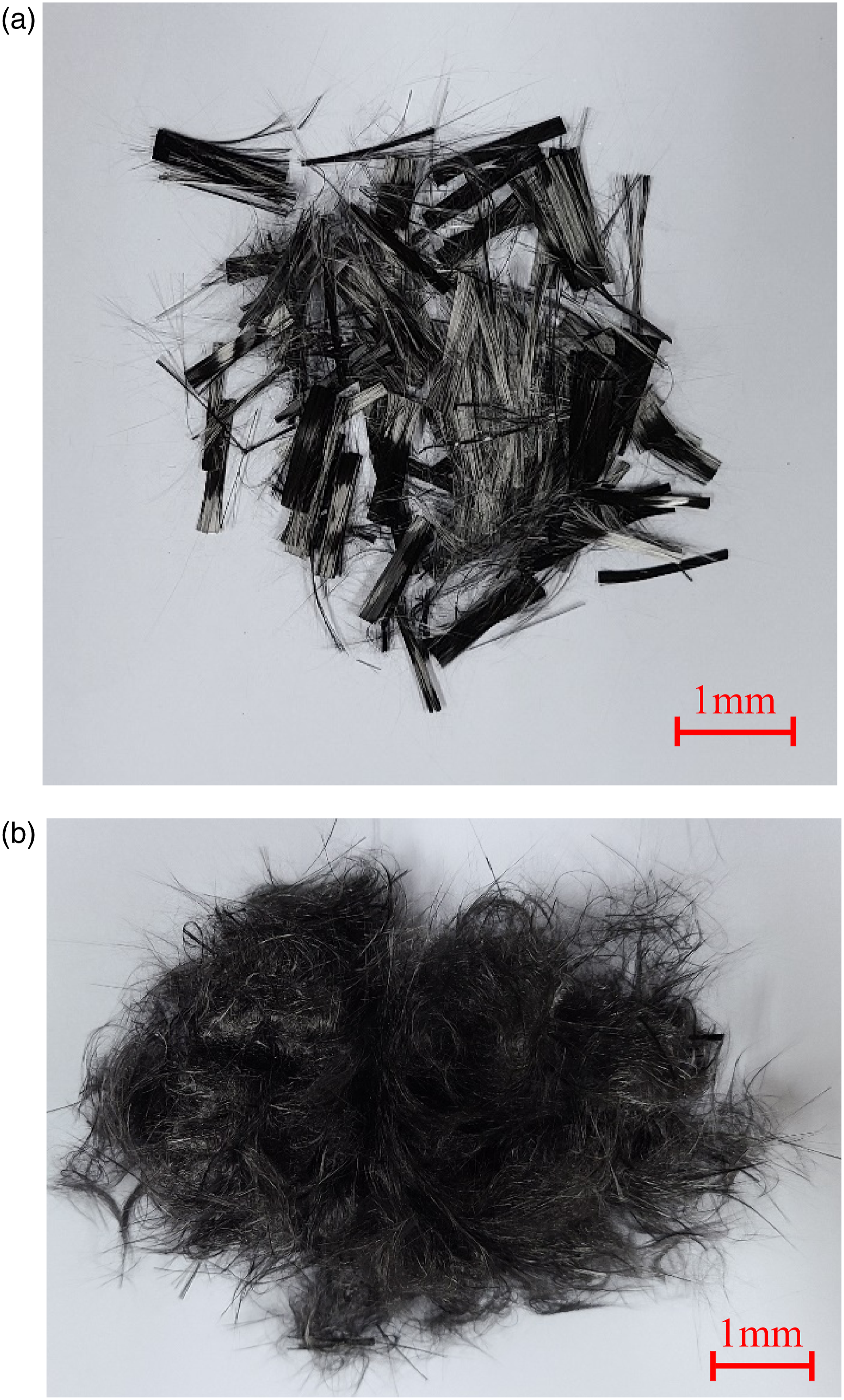
Pneumatic dispersion
The pneumatic method is one of the most prominent methods to disperse fiber with a high-pressure air compressor. Both the original and sizing-removed carbon fiber are laid into the containers, and it is covered by sieves to blow air under high pressure to achieve fiber separation. After the pneumatic dispersion method, both 12 mm and 24 mm chopped carbon fibers were moderately spread into the concrete.
The dispersion of sizing-removed carbon fiber was more prominent than original carbon fiber, and this could be due to the sizing on the surface of the original carbon holding together in some linear strands, as seen in the dispersion result.
Carbon fiber reinforced concrete
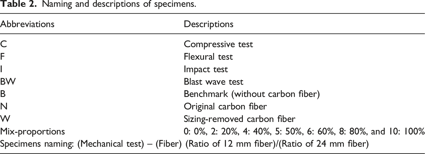
Fineness modulus of aggregates.
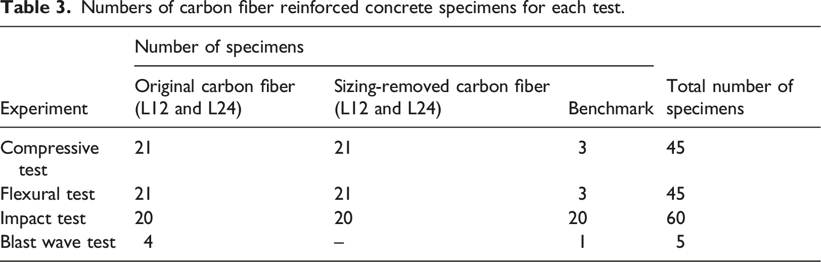
Naming and descriptions of specimens.
Experimental methods
Numbers of carbon fiber reinforced concrete specimens for each test.
SEM/EDS
As both original and sizing-removed carbon fibers were to be used in this study to validate the methods and results of the sizing-removal process, SEM/EDS was used to analyze the microstructure and the surface components of solid materials. The SEM executes at high magnifications and precisely measures the very small features or objects. In this study, both the original carbon fiber and sizing-removed carbon fiber were scanned by SEM/EDS (TM4000plus II, Hitachi High-Tech Corporation, Japan) to produce high-resolution images for analysis. The SEM images show the surface of the carbon fiber at 1000 times magnification, and the EDS graphs show the percentage of the substances on the fiber surface.
Compressive test
To determine the compressive strength of the CFRC with different mix-proportions, cylindrical specimens with dimensions of 100 mm diameter × 200 mm height were tested with the loading rate varying from 900 N/s to 1800 N/s according to ASTM C39/C39M-01 standards.
Flexural test
The flexural strength of CFRC specimens with different mix-proportions was tested as per ASTM C293/C293M-16 under the loading speed of 0.9–1.2 MPa/min, and the dimensions of the specimen were 280 mm × 70 mm × 70 mm (length × width × height). The modulus of rupture (R) is
Impact test
To evaluate the impact resistance of the CFRC in this section, cylindrical specimens with dimensions of 152 mm diameter and 63.5 mm thickness were tested as per (ACI 544.2R-89, 1999). And since flexural strength is a critical property that can absorb the energy produced from the reflected tensile wave during an explosion, the mix-proportion that resulted in the highest flexural strength was used for this test and later for the blast wave test. In addition, Ridha et al. (2017) indicated that the impact resistance of the CFRC specimen with 24 mm carbon fiber was better than that of the CFRC specimen with 12 mm carbon fiber, thus specimens with 24 mm carbon fibers were also tested in this section. The impact test was conducted on four groups of specimens: benchmark concrete, specimens with 24 mm single-length and original carbon fibers, specimens with 50% 12 mm and 50% 24 mm original carbon fibers, and sizing-removed specimens with 50% 12 mm and 50% 24 mm carbon fibers. The hammer was dropped from a fixed height to determine the impact number under different impact energies; the test equipment is shown in Figure 2. The impact energy (E) was calculated using the equation E = m·g·h; where m is the mass of the hammer, g is the acceleration of gravity, and h is the drop height. Impact test equipment.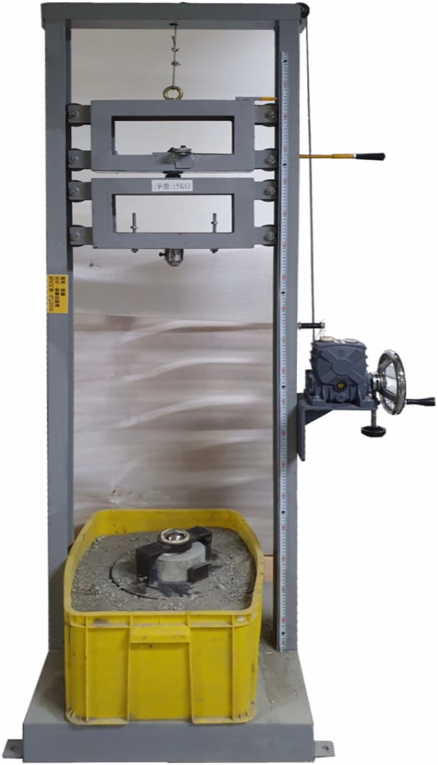
Blast wave test
The blast wave test was conducted to assess the blast resistance of the CFRC specimens. The specimens in this section were prepared in slabs with dimensions of 500 mm × 500 mm × 150 mm thickness and were reinforced with D10 rebar (#3 steel reinforcing bar, nominal diameter of 9.5 mm), as shown in Figure 3(a). The explosive used in the contact explosion test was 150 g of C-4 charge, and it was placed in the center on the front face of the specimen where it would best represent the strongest blast wave. RC slab configurations: (a) Design detailed and (b) CFRC slab with two layers CFRP (B-N5/5-C slab).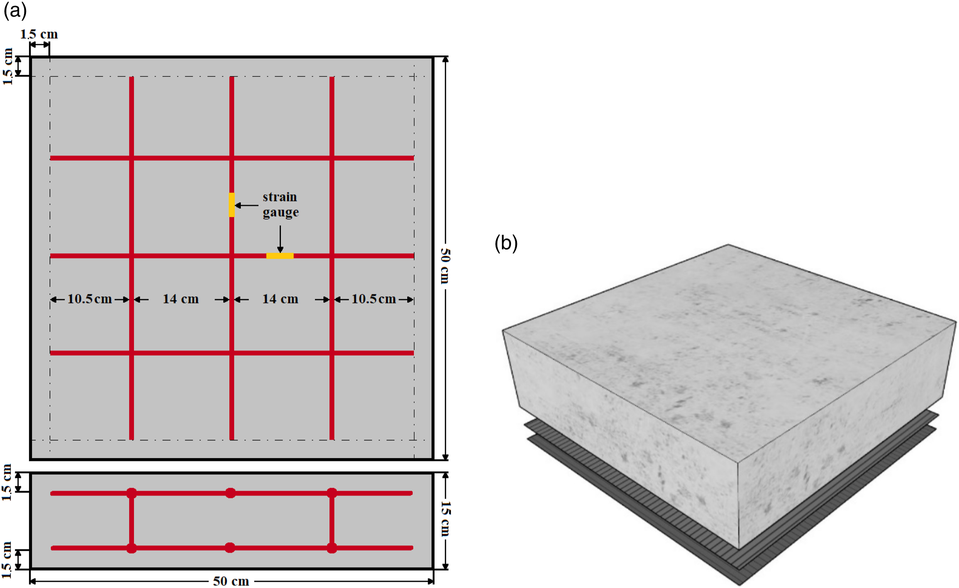
In addition, in order to inhibit the degree of spalling and minimize the damage on the rear side of the CFRC caused by the reflected tensile wave during an explosion, two layers of carbon fiber reinforced polymer (CFRP) sheet were placed perpendicularly to each other with two parts of SB 838 epoxy resin and one part of hardener, and then they were applied, with epoxy resin, onto the rear surface of one of the CFRC slabs, as shown in Figure 3(b). The five specimens in this test were benchmark concrete, 12 mm single-length CFRC slab, 24 mm single-length CFRC slab, 50% 12 mm and 50% 24 mm CFRC slab, and 50% 12 mm and 50% 24 mm slab with CFRP attached. The failure mode and resulting damage measurements were recorded for further analysis.
Results and discussion
CFRC specimens were prepared with a carbon-fiber-to-cement ratio of 1% and 0.6 w/c. The compressive strength, flexural strength, and impact performance of the CFRC specimens are listed below.
SEM/EDS
Since the presence of sizing on carbon fiber can influence the mechanical behavior of CFRC, sizing on some of the carbon fibers was removed through heat-treated methods. The results were examined by SEM/EDS analysis and shown in Figure 4. The SEM image in Figure 4(a) shows the surface of the original carbon fibers, and the presence of some impure substances could be seen. The EDS graph in Figure 4(c) indicates that the original carbon fiber contains about 99.0% of carbon content and about 1% silicon. Figure 4(b) is the SEM image showing the surface of sizing-removed carbon fibers, and comparing with Figure 4(a) the same impure substances are absent. The heat-treated method can effectively remove the sizing on carbon fibers, as can be seen in Figure 4(d) that the composition is 100% carbon. SEM images and EDS graphs: (a) SEM image of impurity on the surface of original carbon fiber, (b) SEM image of sizing-removed carbon fiber, (c) element weight percentage of original carbon fiber in EDS graph, and (d) element weight percentage of sizing-removed carbon fiber in EDS graph.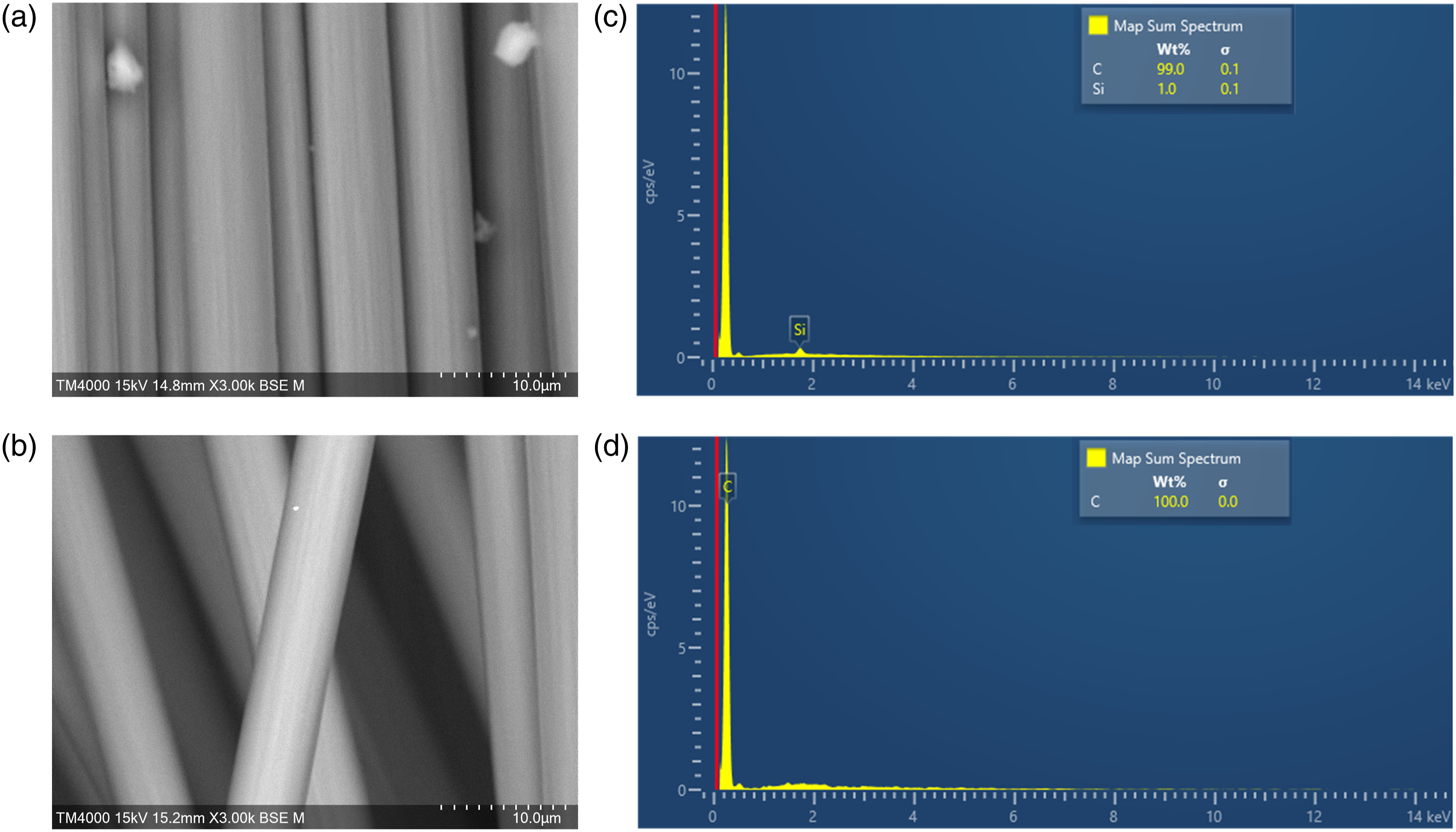
Compressive test
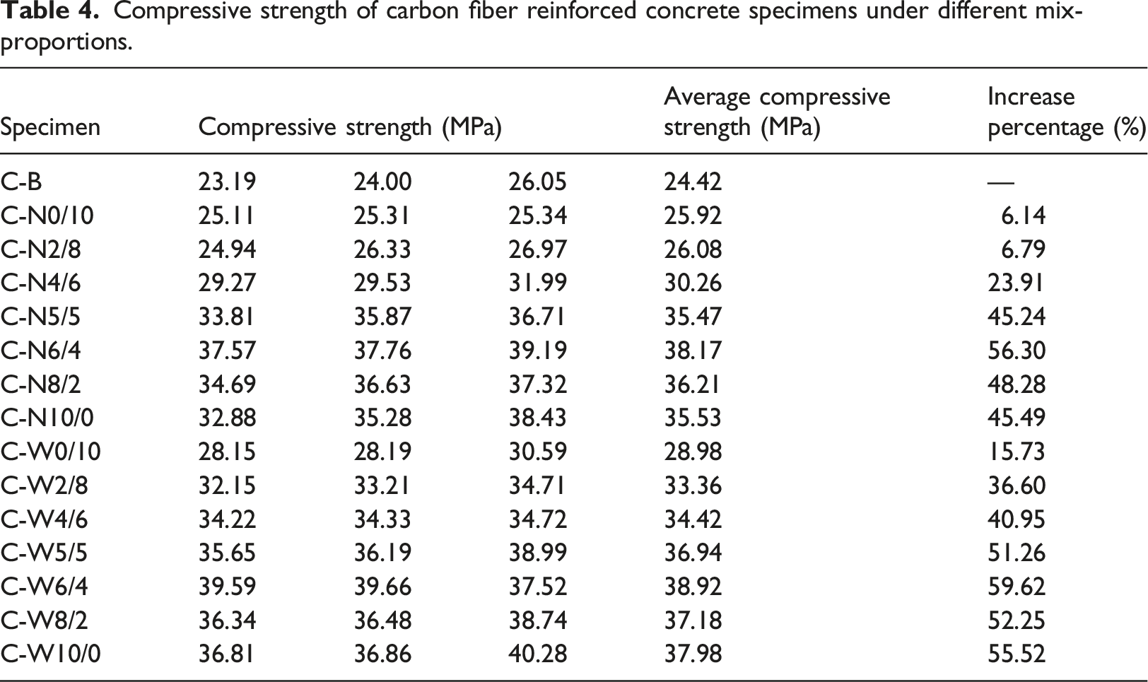
Compressive strength of carbon fiber reinforced concrete specimens under different mix-proportions.
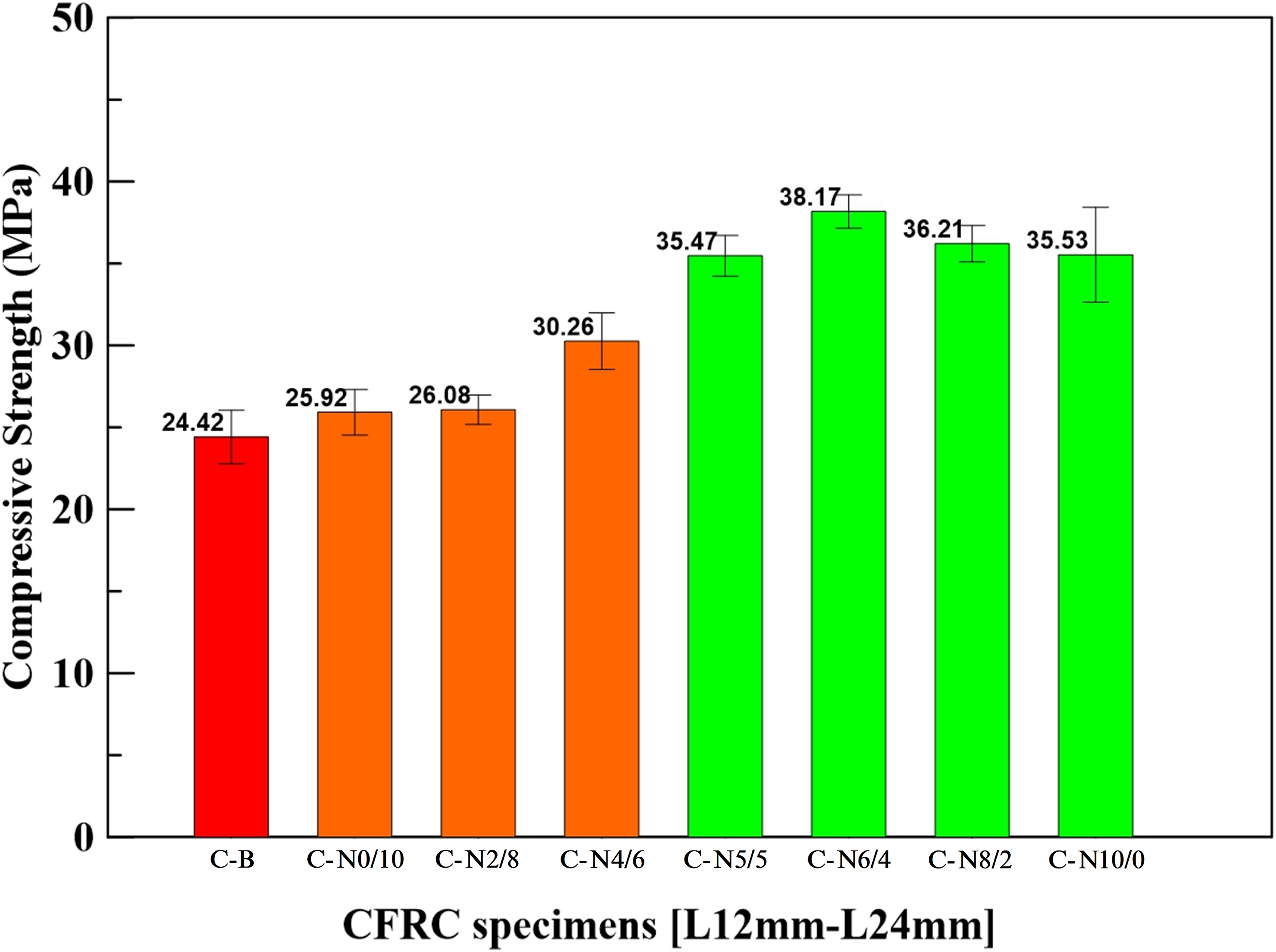
Compressive strengths of carbon fiber reinforced concrete specimens with the original carbon fiber.
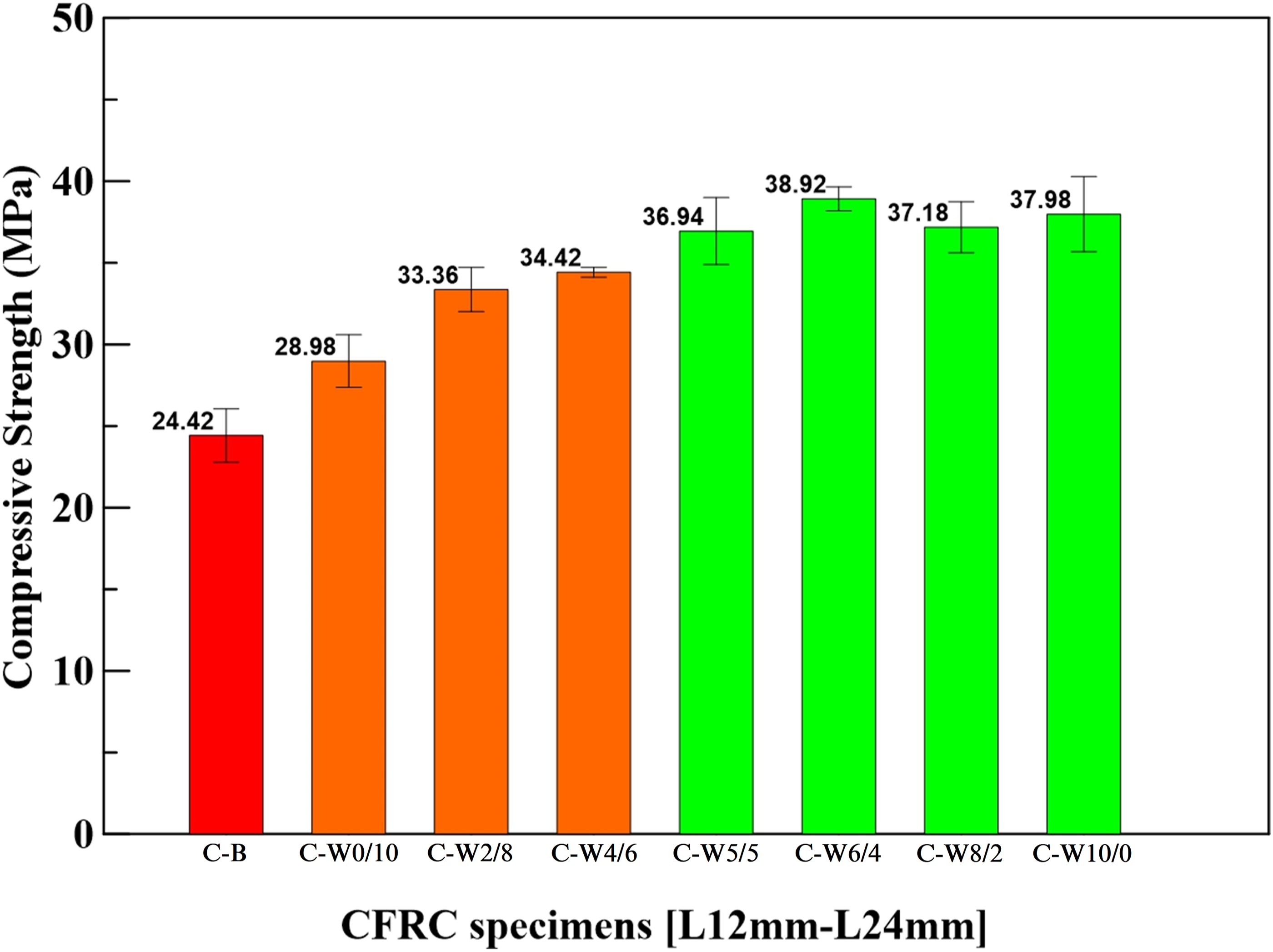
Compressive strengths of carbon fiber reinforced concrete specimens with the sizing-removed carbon fiber.
Flexural test
Flexural strength of carbon fiber reinforced concrete specimens under different mix-proportions.
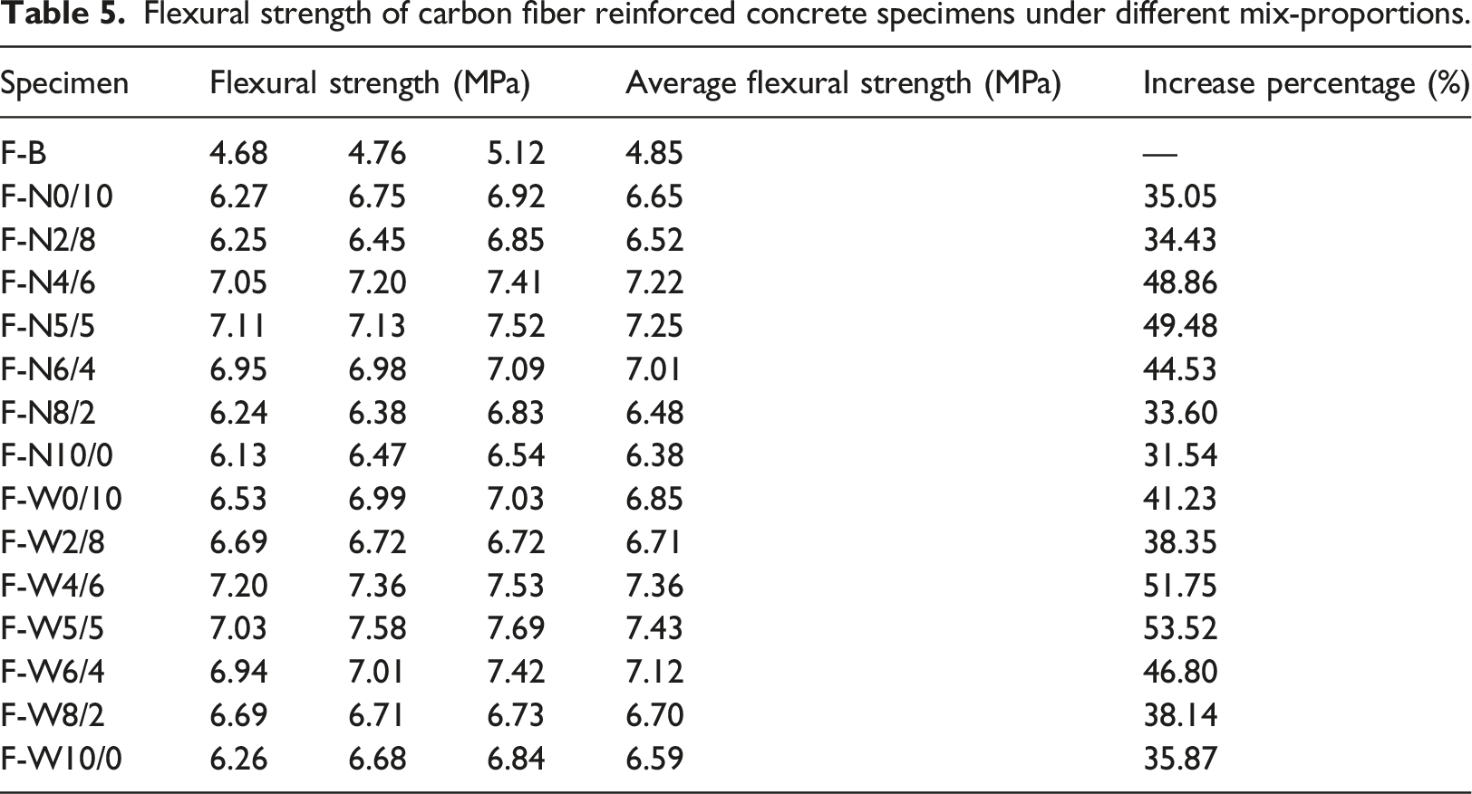
Similar outcomes were found in the CFRC specimens with sizing-removed carbon fiber when compared with the benchmark specimens. Specimen F-W4/6, F-W5/5, and F-W6/4 exhibited higher average flexural strength with increase percentages of about 51.75%, 53.52%, and 46.80%, respectively. Figures 7 and 8 represent the flexural strength of CFRC with original and sizing-removed carbon fiber, respectively. As shown in Figures 7 and 8, the flexural strength of the CFRC specimens with the addition of carbon fiber was all higher than that of benchmark specimens. Results from those two figures also showed that CFRC specimens with sizing-removed carbon fiber demonstrated higher strength than that of specimens with original carbon fiber. It can be concluded that removing the sizing on the surface of carbon fibers could increase the flexural strength of CFRC. Flexural strengths of carbon fiber reinforced concrete specimens with the original carbon fiber. Flexural strengths of carbon fiber reinforced concrete specimens with the sizing removed carbon fiber.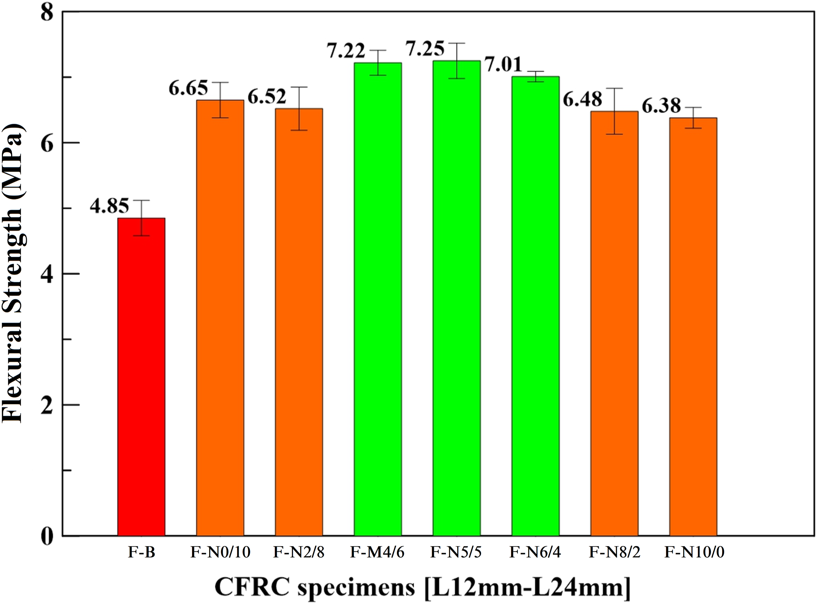
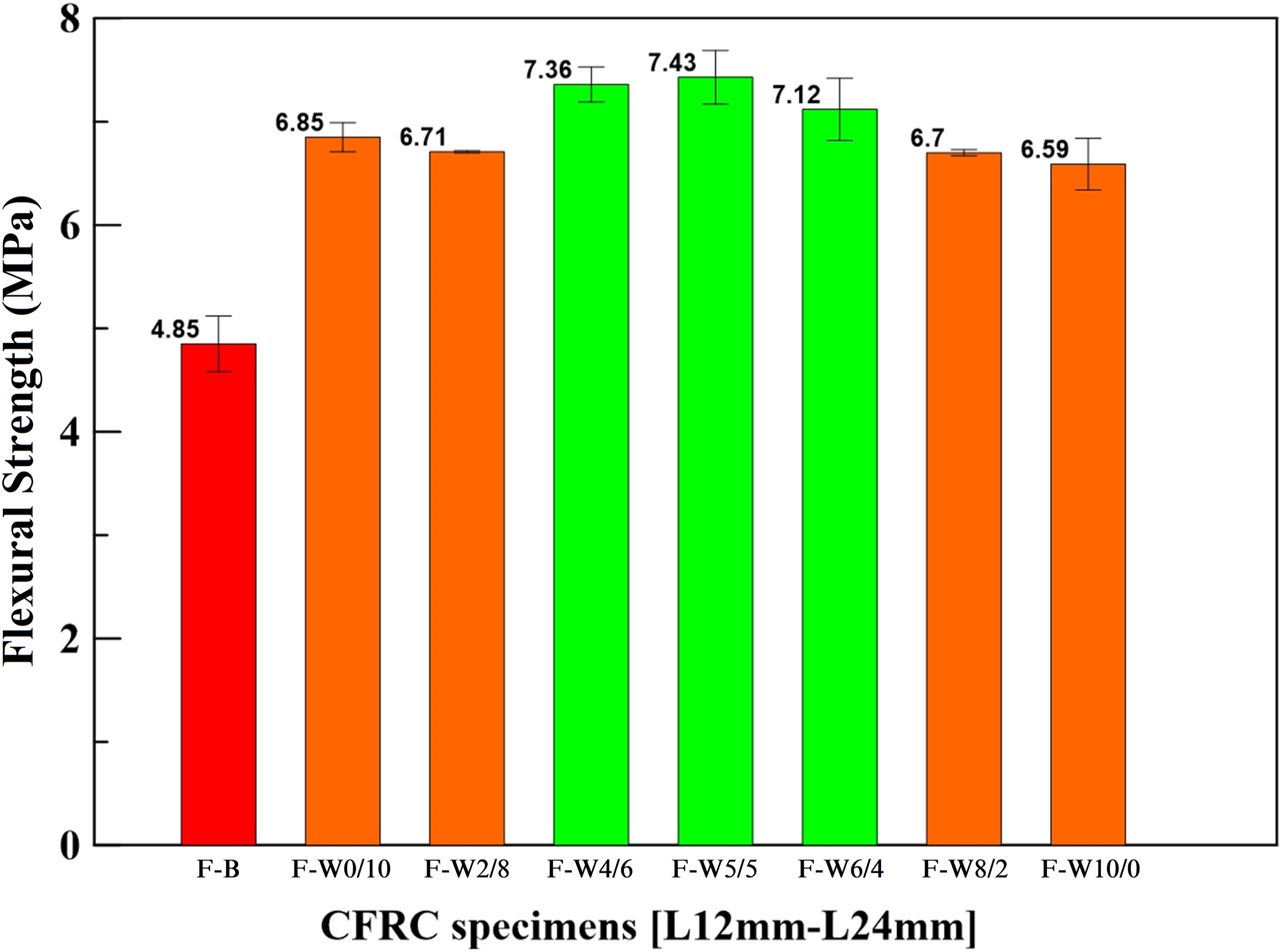
The effect of using mix-proportion carbon fibers on flexural strength was not linear, as seen in Figures 7 and 8. In the case of sizing-removed CFRC specimens, the strength increased from 7.36 MPa at proportion 40%–60% to the maximum strength of 7.43 MPa at proportion 50%–50% and then declined to 7.12 MPa at 60%–40%. This was evident in both original carbon fiber CFRC and sizing-removed CFRC cases. It could be inferred that the flexural strength does not increase with an increase in the ratio of either length of carbon fibers, and the optimal mix proportion for the highest flexural strength was 50%–50%.
Impact test
Impact energy and impact number of carbon fiber reinforced concrete specimens.
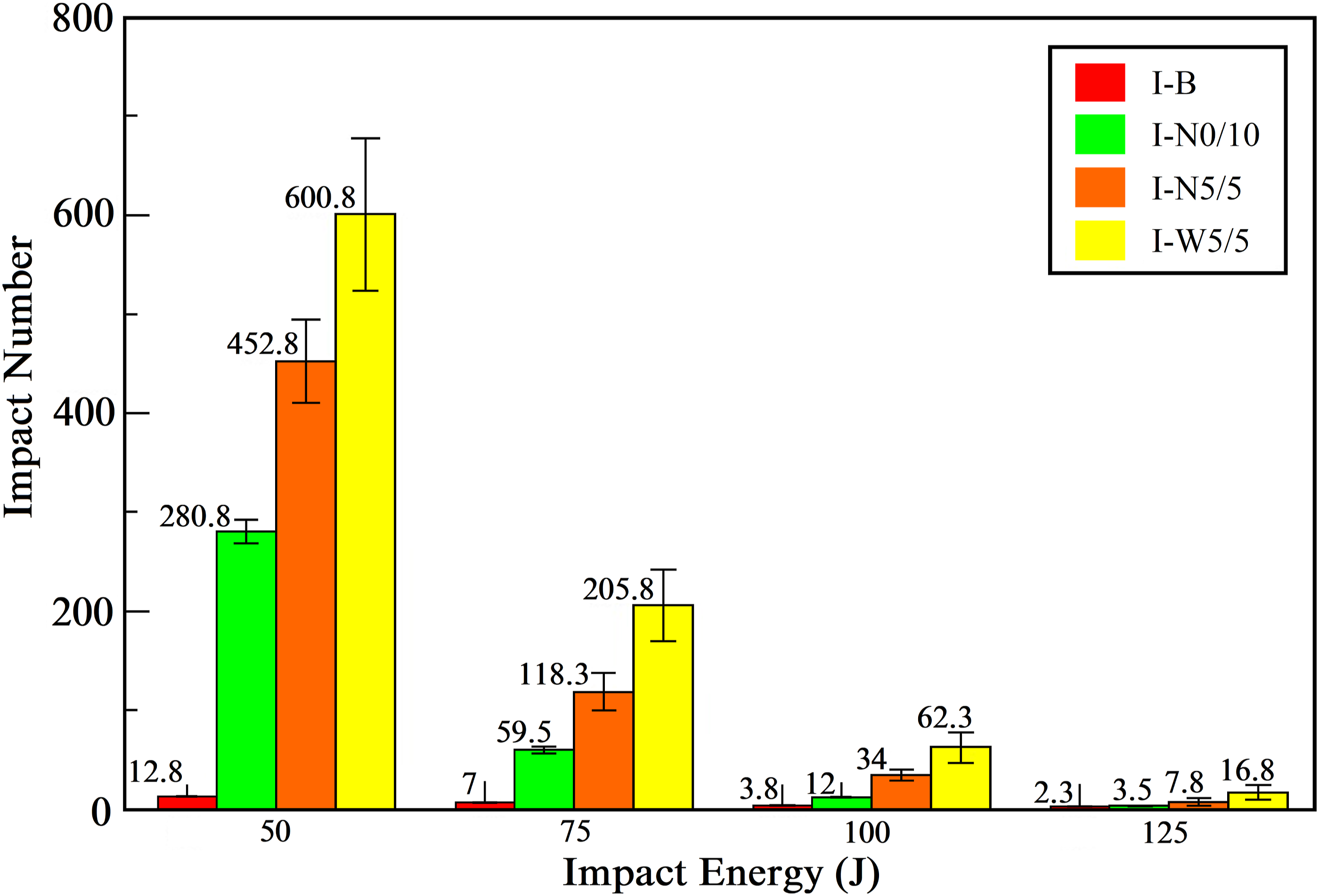
Impact energy-number relationships of benchmark and carbon fiber reinforced concrete specimens.
As seen in the failure photos of CFRC specimens shown in Figure 10, I-W5/5 was broken into four pieces, I-N5/5 in three pieces, and I-B in two pieces. Since impact resistance is related to the number of broken pieces of CFRC, and the higher impact resistant capability results in more broken pieces, I-W5/5 the specimen with sizing-removed carbon fiber was also visually proven to be the specimen with higher impact resistance. This result conforms with the finding mentioned above. Failure photos of carbon fiber reinforced concrete specimens under repeated impact at 50 J: (a) benchmark, (b) carbon fiber with sizing (I-N5/5), and (c) sizing-removed carbon fiber (I-W5/5).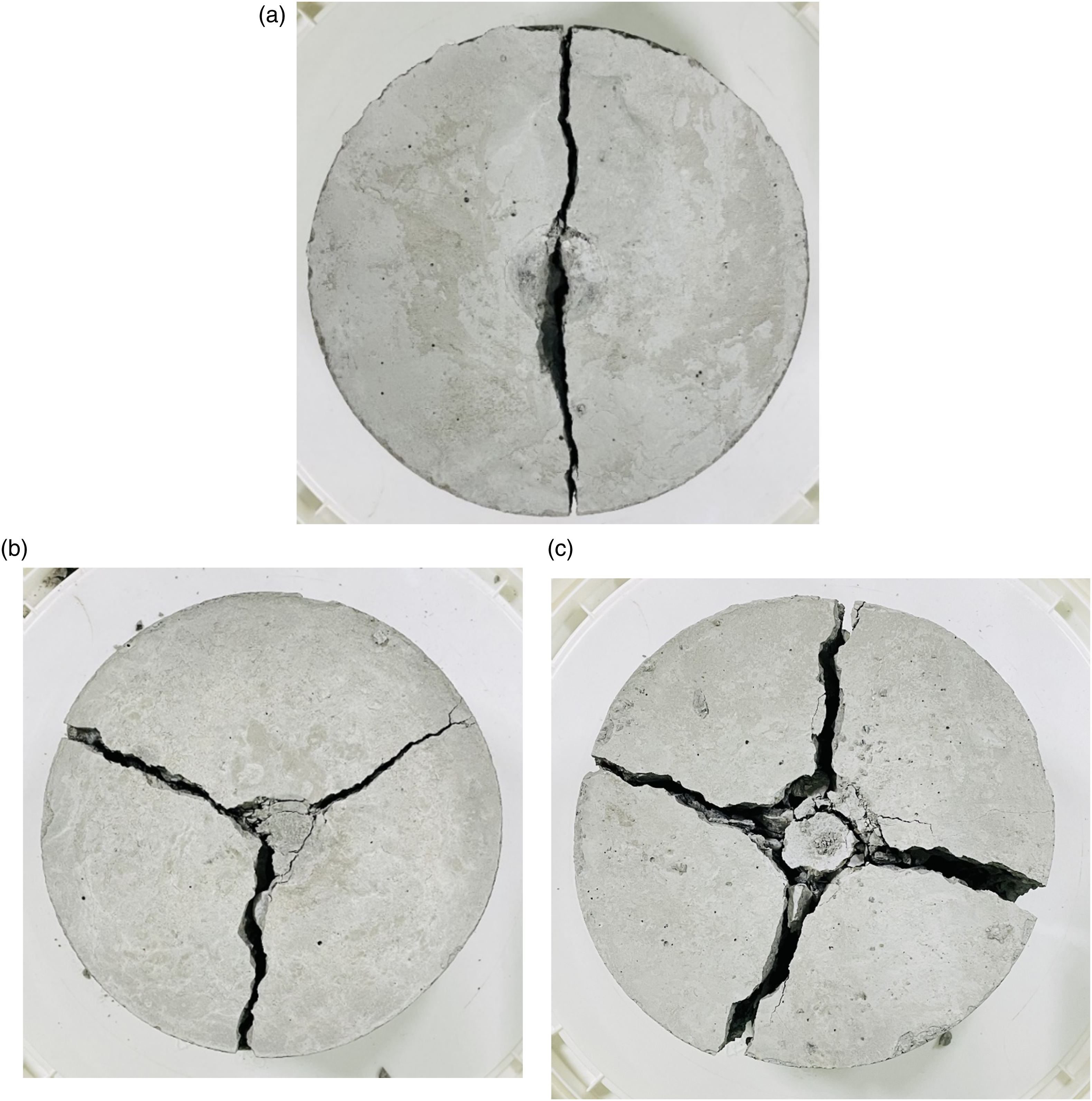
As seen in Figure 11, the damaged CFRC specimens were analyzed in optical microscopic to find out the failure mode of carbon fiber. Figure 11(a) shows the optical microscopic image of the I-N5/5 specimen, and most carbon fibers occurred slippage failure. For the I-W5/5 specimen, most carbon fibers occurred rupture failure, as shown in Figure 11(b). The enhancement of impact resistance by using sizing-removed carbon fiber in CFRC was evident, as in Figure 10, and from the microscopic level, it could also be inferred that adding sizing-removed carbon fiber increases the impact resistance of CFRC. Failure images after impact test: (a) carbon fiber attained slippage failure, and (b) carbon fiber attained rupture failure.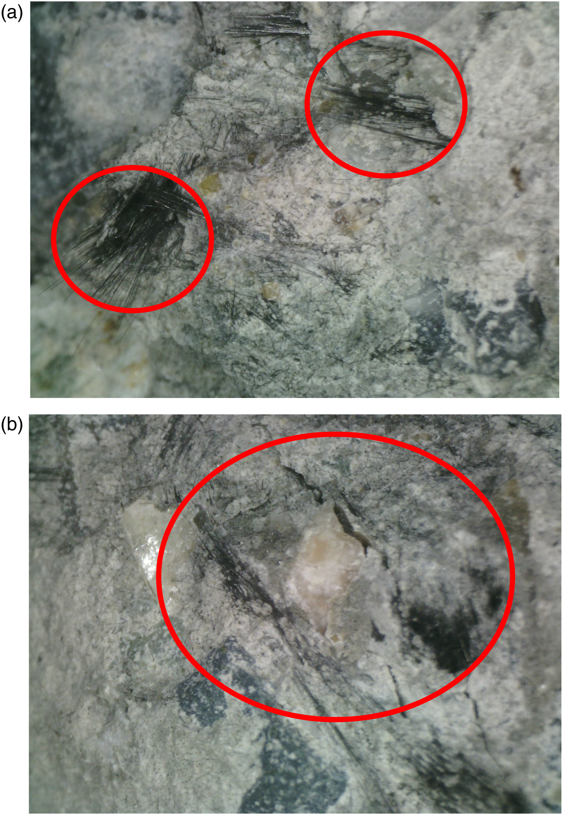
Blast wave test
The blast wave test was used to assess the anti-blast wave performance of CFRC. The explosive used in this contact explosion test was 150 g C-4 dynamite, which is placed on the center of the front face of the specimens, as shown in Figure 12(a). The blast-induced peak pressures were recorded by a pressure sensor (137A21 Free Field Blast ICP® Pressure Probe, PCB Piezotronics, Inc., NY, USA), the maximum measurable pressure up to 1 ksi, positioned at the same height of the explosive center and horizontally distanced at 125 cm. The recorded peak incident pressure for each blast event shows consistent results as seen in Table 7, indicating that all the specimens were subjected to the same detonation energy. The explosion setup and failure image of the slab under blast wave loading: (a) explosion setup, (b) BW-B slab, (c) BW-N10/0 slab, (d) BW-N0/10 slab, (e) BW-N5/5 slab, and (f) BW-N5/5-C slab. Peak incident pressure under 150 g C-4 dynamite for each test event.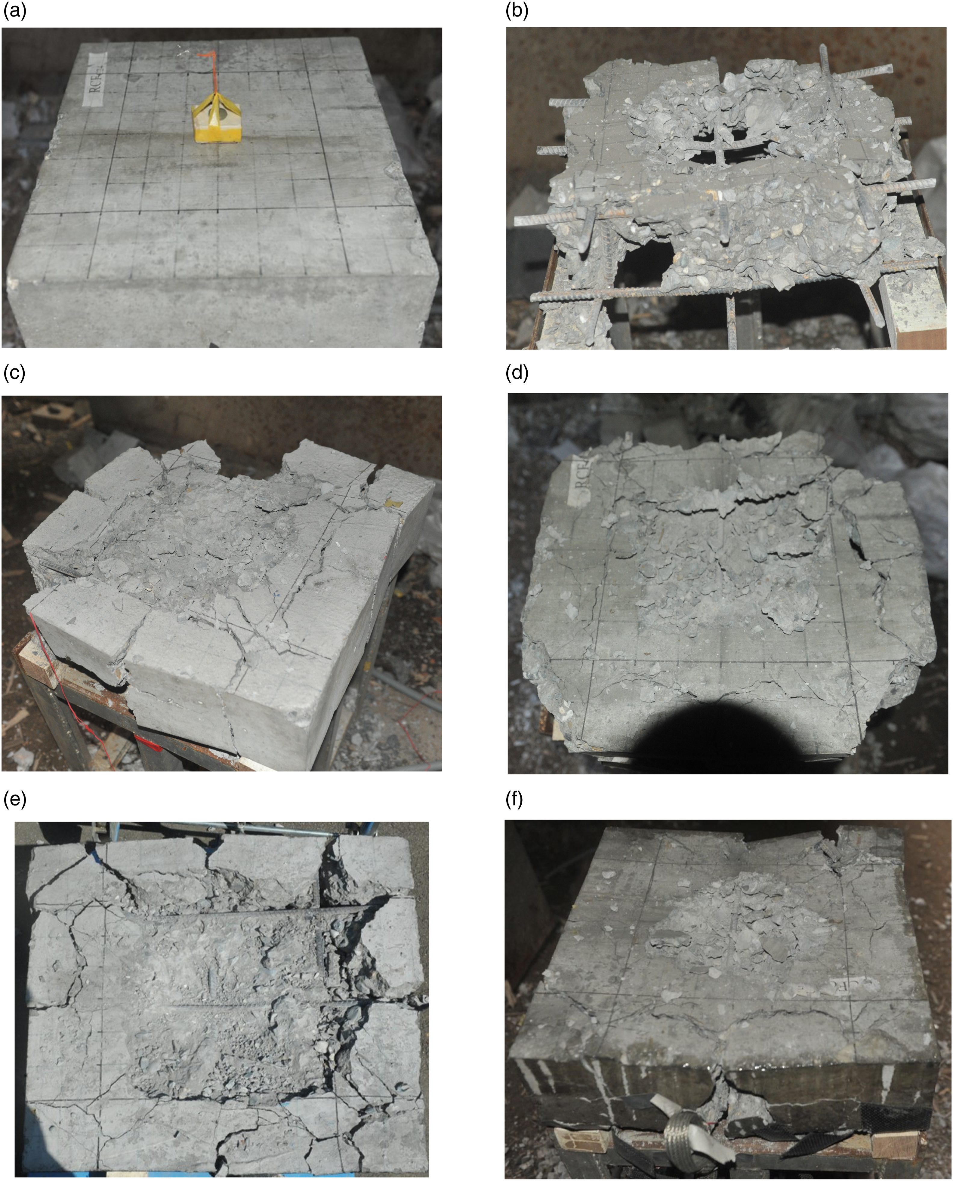
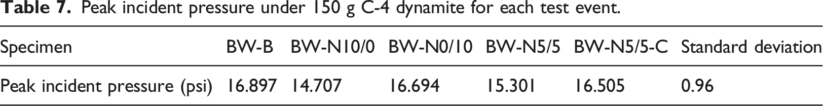
Figure 12(b) is the benchmark slab photo after the blast wave test, and it shows breach failure. Figure 12(c) and (d) show the failure photos of slab BW-N10/0 (CFRC with 12 mm original carbon fiber) and slab BW-N0/10 (CFRC with 24 mm original carbon fiber), respectively (Li et al., 2021a). For the mix-proportion CFRC slabs, Figure 12(e) and (f) are the failure images of BW-N5/5 and BW-N5/5-C (the CFRC with CFRP), respectively. As seen from the above results, the bonding of fiber with cement and aggregates in the concrete composites could increase the blast resistance of concrete materials.
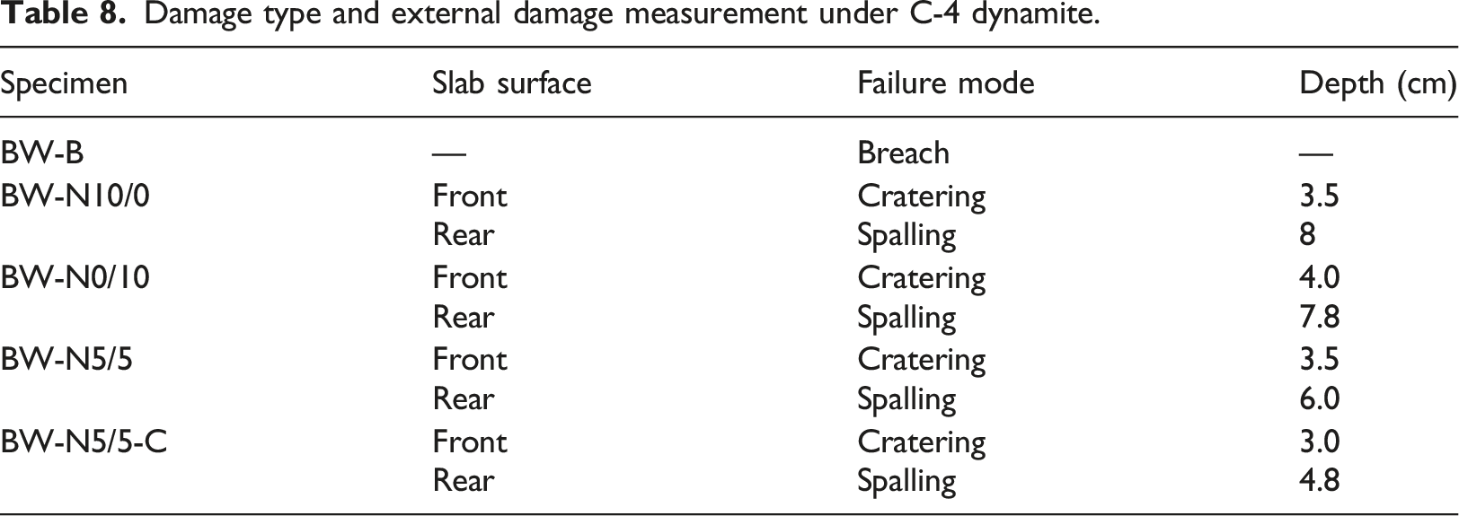
Damage type and external damage measurement under C-4 dynamite.
Conclusions
The purpose of this research is to investigate the mechanical behaviors of carbon fiber reinforced concrete (CFRC) under different loadings, and examine the corresponding effects with different length ratios and conditions (original and sizing-removed) of carbon fiber. The following conclusions are listed below: 1. The sizing-removed carbon fiber CFRC specimens attained the highest compressive strength than other specimens. And the maximum compressive strength of the CFRC specimen appeared in 60%–40% (Specimens C-N6/4 and C-W6/4) mix-proportion of carbon fiber. 2. The higher flexural strength appeared in three different mix-proportions: 40%–60%, 50%–50%, and 60%–40% of the CFRC specimens, in both original and sizing-removed carbon fiber cases. 3. The impact number of I-W5/5 specimens was the best among all specimens. Using sizing-removed carbon fibers can increase the impact resistance of CFRC materials. 4. Adding mix-proportion of carbon fiber pieces into CFRC can result in higher blast wave resistance of concrete when comparing with benchmark concrete and CFRC with single-length carbon fibers. Moreover, attaching layers of CFRP to the rear surface of CFRC could further improve its resistance and could serve as the protection for the object underneath.
Footnotes
Declaration of conflicting interests
The author(s) declared no potential conflicts of interest with respect to the research, authorship, and/or publication of this article.
Funding
The author(s) disclosed receipt of the following financial support for the research, authorship, and/or publication of this article: This work was supported by the Ministry of Science and Technology of the Taiwan government, under contract No. MOST 109-2622-E-606-002, and the “Research Center of Energy Conservation for New Generation of Residential, Commercial, and Industrial Sectors” from the Ministry of Education in Taiwan under contract No. L7091101-19.