
Abstract
Ocular imaging plays an irreplaceable role in the evaluation of eye diseases. Developing cellular-resolution ophthalmic imaging technique for more accurate and effective diagnosis and pathogenesis analysis of ocular diseases is a hot topic in the cross-cutting areas of ophthalmology and imaging. Currently, ocular imaging with traditional optical coherence tomography (OCT) is limited in lateral resolution and thus can hardly resolve cellular structures. Conventional OCT technology obtains ultra-high resolution at the expense of a certain imaging range and cannot achieve full field of view imaging. In the early years, Time-domain full-field OCT (TD-FF-OCT) has been mainly used for ex vivo ophthalmic tissue studies, limited by the low speed and low full-well capacity of existing two-dimensional (2D) cameras. The recent improvements in system design opened new imaging possibilities for in vivo applications thanks to its distinctive optical properties of TD-FF-OCT such as a spatial resolution almost insensitive to aberrations, and the possibility to control the curvature of the optical slice. This review also attempts to look at the future directions of TD-FF-OCT evolution, for example, the potential transfer of the functional-imaging dynamic TD-FF-OCT from the ex vivo into in vivo use and its expected benefit in basic and clinical ophthalmic research. Through non-invasive, wide-field, and cellular-resolution imaging, TD-FF-OCT has great potential to be the next-generation imaging modality to improve our understanding of human eye physiology and pathology.
Background
After 30 years since its development, optical coherence tomography (OCT)1–4 continues to be increasingly applied to medical imaging, and especially in ophthalmology, because of its advantages of high-resolution and high-sensitivity imaging without contact with an eye. The most common OCT nowadays is spectral-domain OCT (SD-OCT).5–9 It relies on the spatially coherent source of low temporal coherence and spectrometer to obtain a one-dimensional (1D) axial in-depth reflectivity profile (the so-called A-line). By scanning the beam laterally, one can reconstruct two-dimensional (2D) cross-sectional images (B-scans) and three-dimensional (3D) volumetric views. 10 Historically, the cross-sectional images were the ones that opened the door for OCT clinical ophthalmology. By comprehensively and objectively observing and evaluating the parameters of the drusen within the retina, clinical doctors were empowered to diagnose and follow up on the offer activeness of treatment against wet age-related macular degeneration (wet AMD) – a challenging ocular condition.11–15
Today modern clinical OCTs are very performant at reconstructing cross-sectional images – at scanning speed of 100 kHz and 1000 pixels field-of-view (FOV) 100 B-scans can be recorded in 1 s (0.01 s for a single B-scan), keeping the physiological motions of the eye effectively frozen. 16 However, cross-sectional imaging is not the most practical modality for evaluating all aspects of ocular health. For example, blood vessels of the retina and limbus of the eye are oriented primarily laterally, which makes en face views preferable as they directly show the vessel branching patterns and the propagating blood flow within them (angiography).17–19 Moreover, cells of the cornea and retina lie in the lateral sheets, therefore quantitative clinical diagnosis based on cell density requires face views. Unfortunately, SD-OCT is less adapted to en-face imaging compared with cross-sectional one. More precisely, to acquire an en face view, SD-OCT needs to scan not in one but in two directions, which requires considerable time (in fact the same time as for the acquisition of a 3D volume).20–22 With the 100 kHz device a single 1000-pixel × 1000-pixel image is reconstructed in 10 s – a too long time to avoid the destructive eye movement artifacts. The acquisition time can be reduced to suppress the movements, however, at a cost of considerably shrinking the visible FOV. Within small FOV, only a few cells can be visible, leading to low precision of potential quantitative diagnosis. The limited frame rate of en face acquisition also sets a low limit for the time precision of angiographic measurements.
Since the early days, in parallel to the spectral domain (Fourier domain) OCT, another class of en face OCT methods have been under development to increase en face imaging speed. Advances in camera technologies and light sources in recent years enabled the rise of en face OCT methods, such as Fourier-domain full-field OCT (FD-FF-OCT),23–26 also known as swept-source full-field OCT (SS-FF-OCT),27–30 line-field OCT (LF-OCT),31–35 ultra-high-resolution OCT (UHR-OCT),36–42 and so on. An excellent review of en face OCT methods can be found. 43 In this article, we will limit ourselves to a single method – time-domain full-field OCT (TD-FF-OCT) and its development progress and future in the ophthalmic imaging field.
Fundamentals of TD-FF-OCT
Basic principle
TD-FF-OCT, demonstrated by Beaurepaire et al., is an en face OCT that uses full-field illumination and a parallel array (camera) detection to accelerate en face imaging.44,45 When the speed of axial or lateral motion is lower than the camera exposure time, TD-FF-OCT can capture all camera pixels without horizontal scanning, which leads to suppression of the potential motion artifacts coming from the sample. TD-FF-OCT’s primary sectioning orientation is en face, there is usually no need to keep the large depth-of-field (DOF) optics. Its detection geometry makes it more suitable to maintain the best resolution at different depths by changing the focal plane according to the coherent plane. Therefore, typically high numerical aperture (NA) microscope objective can be used to achieve micrometer-level lateral resolution. The latter is given by the Rayleigh criterion extensively used in optical microscopy as shown in equation (1). Full-field illumination, 2D camera, and microscope objective largely remind of the classical microscope designs; however, TD-FF-OCT also adds the second optical arm with a reference mirror to achieve optical gating. Another essential requirement for optical gating is a light source of low temporal coherence, ensuring that light back-scattered from only one slice of the sample will interfere with the reflected light from the reference mirror. The more broadband is the light source spectrum – the smaller is the temporal coherence and the thinner is the interfering sample section [higher axial resolution; equation (2)]

where ∆x and ∆y are the resolutions in lateral directions, ∆z is the resolution in the axial direction measured by full-width-half maximum (FWHM), λ is the central wavelength and ∆λ is spectral bandwidth of the light source, and n is the refractive index of the sample tissue. 44 It can be noted from the above that the horizontal resolution is separated from the axial resolution, which is common in the OCT method (Figure 1). However, a high NA objective lens can limit the DOF of axial resolution.

Schematic of FF-OCT. Left: Diagram of a conventional FF-OCT in a Linnik interferometer. Right: Diagram showing FF-OCT takes en face images with planes (xy) that are perpendicular to the optical axis (z).
Bright-field illumination in TD-FF-OCT can be achieved with low-cost light sources of low spatial coherence such as halogen lamps or light-emitting diodes (LED). These sources bring the advantage that they produce images free from unwanted cross-talk effects (speckle) 46 that typically degrade the images in the coherent-light OCTs.
Image reconstruction
It is worth stating that the equations in this section are mainly used by TD-FF-OCT in human in vivo eye imaging, and may differ in detail for other uses of imaging, and the imaging equations in other scenarios and more details can be found in the references.44,47 TD-FF-OCT first prevents defocus light from reaching the detector, then detects the entire bright field, and then relies on the rear demodulation scheme to generate the optical part. Each bright-field image on the camera contains: (1) ballistic single-scattered light from the sample optical section and reflected light from the reference mirror that interferes (‘coherent’ light) and (2) light that does not participate in interference (‘incoherent’ light) from the other layers of the sample, from the reference mirror, stray light reflected from optical components, as well as the multiply-scattered light from the sample optical section. The goal of TD-FF-OCT is to suppress the ‘incoherent’ light and keep the ‘coherent’ light thus producing an optical section. This is done by using the fact that the optical phase of interfering light can be easily controlled by shifting the reference mirror. By varying the reference mirror position in time (thus the name ‘time-domain’ FF-OCT), one can record several bright-field images with different phases. Change in the phase corresponds to different intensities on the camera and different brightness of the detected pixel. Using the fact that the phase modulation affects only the intensity of interfering light, one can easily reject the static ‘incoherent’ background in the images and retrieve an optical section. There exist many phase-modulation schemes that differ in the number of bright-field images used. In the simplest example of two-phase modulation, two images are acquired on the camera as given by Equation (3)48,49

Here I1 and I2 are the detected intensities on the camera for the first and second bright-field images, respectively; I0 is the photon flux of illumination, Rinc is the ‘incoherent’ reflectivity from all the sample structures and optical system parts, Rcoh−sam (x,y) is the ‘coherent’ reflectivity from all sample structures lying within the coherence volume, Rref is the reflectivity from the reference mirror, ϕ(x,y) is the phase difference between the sample and reference signals (denoting fringes in the 2D image), ψ is the additional phase, determined by the axial position of the reference mirror. The latter is typically changed by modulation with a piezoelectric motor. By modulating the piezo motor with a step-like function that: (1) keeps the phase constant during the acquisition of each camera frame and (2) has an amplitude of π, one can reject the ‘incoherent’ light as given below

Taking a square and keeping the non-homogeneous (dependent on x, y) terms, we get

As one can notice, although the two-phase demodulation scheme produces an optical section, it cannot demodulate the interference into the perfectly separate amplitude and phase components – Equation (5) contains reflectivity amplitude Rcoh−sample(x,y) but also the phase component ϕ(x,y). The latter is responsible for interference fringe artifacts that are degrading the TD-FF-OCT images, particularly images from the uniform reflecting layers (such as corneal endothelium).
Other phase schemes allow complete demodulation of interference into amplitude and phase components but require more bright-field images. In the case of four-phase modulation, we get

Then the amplitude and phase can be retrieved as

The latter demodulation method is free from interference artifacts.
Sensitivity
Sensitivity is defined by the smallest signal that can be detected with TD-FF-OCT [when the signal-to-noise ratio (SNR) = 1] 44

where Rmin is the minimum detectable reflectivity at SNR = 1, ξ is the full-well capacity (FWC) of the camera, χ is the electric noise of the camera, and N is the number of averaged TD-FF-OCT images.
The above Equation (8) can be understood intuitively. The camera in TD-FF-OCT acquires bright-field images. The detected light contains interference signals that denote themselves by the small brightness variations on top of the much brighter incoherent background. The high FWC allows for detection of more photons and better resolves the intensity variations in the bright scene (better sensitivity). It is interesting to note that the dynamic range is a much less important parameter. Indeed, the high dynamic range makes the device sensitive to variations between the dark and bright pixels, but less to small brightness variations in the bright scene.
For FF-OCT, there are usually two ways to improve the sensitivity. One is to increase the FWC of the camera, while the other method is to use a reference mirror with a similar reflectance to the total reflectance of the incoherent light in the optical system. Typically, biological samples have reflectivity below 10%. For example, corneal reflectivity is ~2% [determined by Snell’s law and refractive indexes of the air (1.0) – corneal tear film (1.336) interface]. A close refractive index of 4% can be achieved by using the glass reference mirror. Finally, averaging TD-FF-OCT images reduces the noise and improves sensitivity.
TD-FF-OCT in ex vivo and animal ophthalmic studies
At the time of its introduction in 1998, TD-FF-OCT was limited to studies of ex vivo static samples, as no high-speed high-SNR cameras were available at that time. Nevertheless, ex vivo biological and medical research saw a great value in a micron-level resolution introduced by TD-FF-OCT as it enabled rapid histological evaluation of ex vivo tissue samples and brain tissue characterization,50–56 the study of embryology and developmental biology,57–59 and so on. The particular interest attracted the morphological visualization of ophthalmic tissues (cornea and retina) aspiring to bring both a deeper scientific understanding of the eye function and help patients in clinics (for example, by evaluating the quality of the transplantable corneal grafts).
Ex vivo imaging of animal eyes
To open possibilities for ex vivo studies, an adaptation of the original TD-FF-OCT architecture was required. In 2004, Dubois et al. 60 replaced the original design utilizing polarized optics and photo-elastic modulator for phase-shifting with the new design using non-polarized optics and piezo-mirror in the reference arm.
The same year, Grieve et al. 50 applied the new TD-FF-OCT design for studying the structure of anterior and posterior eyes ex vivo for the first time (Figure 2). Ex vivo mouse, rat, and porcine eye samples were under the study. The work used the slow CCD camera with a frame rate of 15 frames per second (FPS) – sufficient for studying the ex vivo samples. Phase modulation was achieved by moving the reference mirror with a piezo-electric actuator. The light source was a tungsten–halogen lamp with a visible central wavelength of 770 nm and broad spectral range of 350 nm. The latter resulted in the sub-micron 0.7 µm axial resolution in tissue. At the same time, microscope objectives with NA of 0.3 (10×) or 0.5 (20×) were provided lateral resolutions of 1.4 and 0.8 µm, respectively. The microscope objectives were water immersion to reduce the specular reflection from the sample surface and increase the interference contrast. Thus, the system was in contact. Due to the low FWC of the camera used, the final TD-FF-OCT image was reconstructed after accumulating (averaging) 5–10 images. The time of 1 s required to produce an en face tomographic image was greatly faster compared with the time required for cross-sectional scanning OCT at that time.
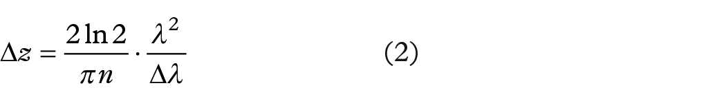
Ex vivo full-field OCT imaging of animal ocular. (a–c) Anterior segment of a mouse eye. (a) The raw image inside the anterior cortex, (b) keratocytes, and stromal fibers, (c) tightly packed epithelial cells. (d–f) Ex vivo full-field OCT imaging of rodent and porcine retina samples. (d) Pig photoreceptors, (e) the nerve fiber bundles in the rat retina, and (f) image showing the rat plexiform and nuclear layers.
The images revealed cell-level details in the rat and mouse corneas. Few microns large epithelial and stromal keratocyte cells in the cornea, as well as fibers in the lens of the eye, were clearly resolved in en face views. Cross-sectional images, reconstructed from the stack of en face images have also shown a great level of detail: different epithelial layers, Bowman’s membrane, stroma, Descemet’s membrane, aqueous humor, lens capsule, lens epithelial cells, and cortical lens fibers could be resolved in the anterior eye.
In addition to corneal images, the researchers also obtained retinal images. They removed the anterior segment from the whole eye and lowered the microscope objective directly into the vitreous. In the rodent and porcine retina samples, many layers were visible in cell detail, including: photoreceptor layer (PRL), external limiting membrane (ELM), outer nuclear layer (ONL), outer plexiform layer (OPL), inner nuclear layer (INL), inner plexiform layer (IPL), ganglion cell layer (GCL), nerve fiber layer (NFL), outer segment (OS), inner segment (IS), as well as retinal pigmental epithelium (RPE), Bruch’s membrane, choroid, and sclera.
This work highlighted the importance of en face views that were rarely used in OCT and histology at that time. While cross-sectional imaging was best suited for evaluating the thickness of the retinal layers, en face views could be used to measure the cellular organization.
Ex vivo imaging of human donor eyes
In 2007, Akiba et al. 61 reported the first subcellular imaging of a human donor cornea and the visualization of a 2D keratocyte network by TD-FF-OCT. In their study, TD-FF-OCT provided en face images that could delineate the morphological features of a human cornea at a subcellular level. Corneal epithelium, keratocytes in stroma, and endothelium were clearly observed.
Later in 2015, Ghouali et al. 62 has shown the value that high-resolution imaging of TD-FF-OCT can bring to clinics (Figure 3). Ex vivo corneas from healthy human subjects were compared with the corneas from human patients affected with various pathologies. The commercial TD-FF-OCT device (LightCT, LLTech, Paris, France) that was used had similar characteristics as the experimental device described above, and also had an added easy-to-use interface. TD-FF-OCT could detect corneal edema, abnormalities caused by pathologies such as keratoconus, keratitis, and Fuch’s endothelial dystrophy. Each condition could be distinguished from one another by: (1) checking the depth of the corneal layer affected, (2) measuring the density of corneal cells, (3) checking for deposits and inclusions in the tissue, (4) checking the global/local corneal opacification, and (5) irregularity in the thicknesses of corneal layers. The cornea is a transplantable tissue. In this context, the mentioned study is particularly valuable, as it provides an additional high-detailed way to examine the health of corneal transplants. Thus, potentially providing a better outcome for the patient following the surgery. Moreover, no tissue preparation, modification, or staining of any kind is required for TD-FF-OCT imaging, which makes it potentially suitable for use in corneal banks.

Organ-cultured normal cornea after de-swelling in a dextran-containing medium. (a) Cross-sectional slice with marked layers; EP, epithelium (38 mm thick); BM, Bowman’s layer (11 mm thick); S, stroma (510 mm thick); DM + E, Descemet’s membrane (10 mm thick) and endothelium. (b–g): ‘En-face’ images. (b) Superficial epithelial layer; (c) wing cell layer; (d) basal epithelial layer; (e) basal epithelial cells, basement membrane (hyper-reflective zones), and Bowman’s layer (hypo-reflective zones). (f) Stromal keratocytes and lamellae of collagen bundles. (g) Endothelial cells were revealed by decreasing axial resolution (sum of ten 1 mm thick slices). The bar shows 70 mm in (a) and 100 mm in (b–g). Reproduced from the study by Ghouali et al. 62 (www.tandfonline.com).
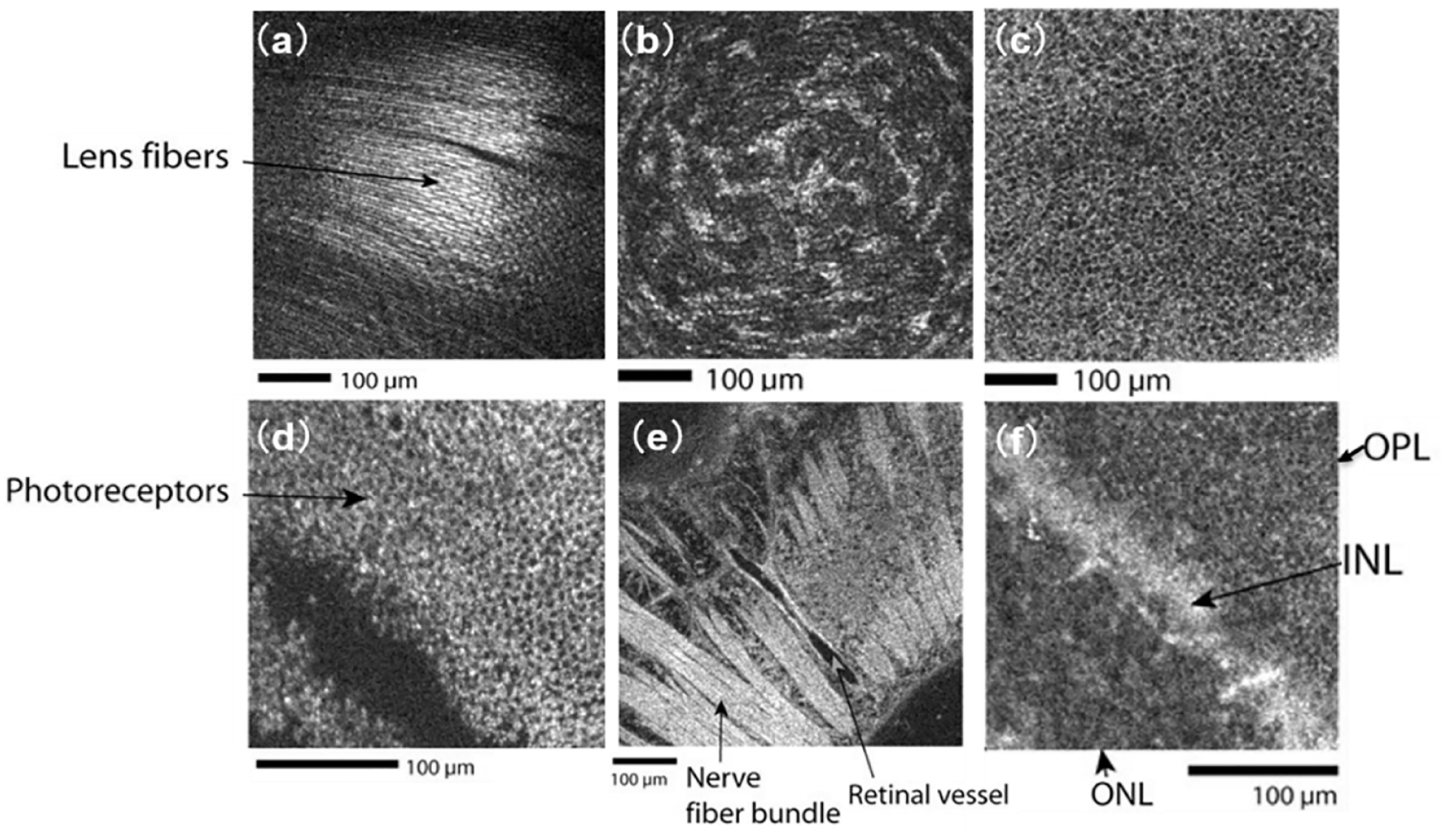
In 2015, Grieve et al. 63 created a new device that combined TD-FF-OCT with fluorescence confocal microscopy (FCM) to gain more biological insights into the ex vivo human retina (Figures 4 and 5). TD-FF-OCT device was specially adapted for high-resolution imaging: (1) water immersion microscope objectives had 0.8 NA leading to 1.6 µm lateral resolution, (2) CMOS camera had an increased FWC of 200 ke leading to higher sensitivity to interference contrast variations. The resolution down to the single cell and single axon provided one of the most detailed optical tomographic images of the retina at that time.

Full-field OCT images of human ex vivo retina. (a) Illustration of the fundus showing raphe median region running from macula to periphery. One through four indicate approximate zones of en face images in row (b) NFL and row (c) GCL. Scale bar: 50 μm. Republished from the study by Grieve et al. 63
Full-field OCT and FCM in humans and fluorescence-FF-OCT in primates. (a, b) Full-field OCT (left) and FCM (right) images of the human retina, in subject three. (a) Sparse axons and cells at periphery visible as hyperreflective structures in FF-OCT (left) and similar region with FCM labeled with Tuj1 (red), which labels ganglion and amacrine cell somas and axons; (b) densely packed cells in GCL in a location closer to the optic nerve, where cells, nerve fibers, and capillaries are visible as hyperreflective structures in FF-OCT (left) and in the similar region with FCM (right) where ganglion cell nuclei are labeled with Brn3a (red). (c) Full-field OCT (left) combined fluorescence-FF-OCT (center) and fluorescence (right) images of GFP-labeled RGC somas in live macaque retina using fluorescence-FF-OCT, with pixel to pixel overlay. Scale bars: 100 μm. Reproduced from the study by Grieve et al. 63
In 2019, Bocheux et al. 64 showed that commercial TD-FF-OCT devices (LightCT, LLTech, Paris, France) can quantitatively measure corneal transparency. This makes the device promising as a screening test for corneal grafts to determine their suitability as transplants.
A notable attempt at the first in vivo TD-FF-OCT imaging was performed by Grieve et al. 65 back in 2005. They used a maximum repetition rate of 250 Hz to obtain images of the anterior eye of anesthetized rats in 4 ms and obtained tomographic images of different corneal and lens layers. This result was important as a proof of concept of in vivo imaging; nevertheless, the possibility of applying the device for an examination of in vivo human eye was a long way beyond the reach of the device. More precisely, the instrument used white light illumination that is known to introduce strong visual discomfort. The use of white light also brings the risk of photochemical damage to the retina in addition to the thermal one, defined by the ISO 15004-2:2007 standard. The xenon arc lamp light source was emitting continuous illumination that could not be pulsed to assure the ocular safety (by decreasing the power absorbed by the ocular tissues over time). The water-immersion objectives increased the image contrast, however, made the instrument contact impractical for use in humans.
TD-FF-OCT for corneal elastography
In 2013, Nahas et al. 66 produced an elastography image of the cornea by correlating the TD-FF-OCT volumes before and after the controlled deformation. The strain of the epithelium layer was found to be about two times larger than that of the stroma.
Dynamic TD-FF-OCT
In 2016, Apelian et al. 67 introduced a new contrast imaging method that relies on the live activity of cells. The method is based on the principle that small movements of intracellular organelles can substantially shift the interferometric fringes (or change their contrast). By acquiring a time-stack of TD-FF-OCT images, one can assign the frequency of pixel modulation to one channel of the colormap (H), the standard deviation of the frequency to the second channel (S), and the cumulative signal sum to the third channel (V). Thus, the method produces a colored TD-FF-OCT image, where color is connected to live activity. This label-free contrast method was named dynamic TD-FF-OCT.
Regarding ophthalmic imaging, Scholler et al. 68 obtained impressive images of retinal organoids using dynamic TD-FF-OCT. The method opens a new window of opportunities for understanding the biological processes inside the cells and functions of individual organelles.
The dynamic method is also useful to follow wound-healing process in ex vivo corneas and retinas (Figure 6). 69 This method allows to measure the cell migration speed and follow the metabolic activity of the cells around the wound.

(a) 3D reconstruction of a D-FF-OCT image stack in explanted macaque retina over a 120 by 120 µm field of view. (b, c, e) En-face images of the (b) inner nuclear layer, (c) outer nuclear layer, and (e) photoreceptor layer. (d) Reconstructed cross-section at the location represented by the red dotted line in (a). The cross-section in (d) was linearly interpolated to obtain a unitary pixel size ratio. (f) D-FF-OCT image of a porcine retinal pigment epithelium cell culture. (g) Overlay of colored D-FF-OCT and FF-OCT at the interface between the layers of the nerve fibers (white arrows point to nerve bundles that are very bright in static and invisible in dynamic mode), ganglion cells (blue and green cells, visible in dynamic mode), and inner plexiform (fibrous network, bottom left, visible in static mode). Samples were maintained in vitro in a culture medium at room temperature during imaging. Reproduced from the study by Scholler et al. 69
TD-FF-OCT in human eyes in vivo
First in vivo human corneal and retinal imaging
The first TD-FF-OCT imaging of in vivo human eye was achieved in 2018 by Mazlin et al. 70 and Xiao et al. 71 Part of the success was due to the use of the new custom-made camera with a high FWC of 2Me – about 10 times larger than existing alternatives. This allowed to collect more photons per frame and have a higher sensitivity to small light intensity variations (interference signals) within the bright scene. As a drawback, this required sending more photons into the eye and additional work to ensure ocular safety. High-intensity illumination was achieved by using a high-power LED with a small chip about the size of the imaged area, thus ensuring the effective coupling of the light from the source. The LED was triggered in a pulsed mode (typical pattern: 3.5 ms illumination, 100 ms no illumination), to keep the power way below the maximum permissible irradiance specified by ISO and ANSI light safety standards. Illumination from the LED with a wavelength of 850 nm was comfortably visible as a dim red circle due to the low sensitivity of the retina to near-infrared (NIR). The air microscope objectives made the instrument non-contact (2 cm between the eye and device).
The corneal and retinal imaging systems had a few differences. In the corneal imaging system, the reference mirror was a neutral density glass filter, producing the 4% light reflection only from the front glass surface. This reflectivity was selected to be close to 2% from the air tear–film interface to ensure the highest sensitivity. In retinal imaging devices, which used optics of the eye (cornea, lens) for focusing, the reflectivity of the retina was insufficient to saturate the camera. To ensure saturation, the reference mirror with a higher reflectivity (Aluminum – 30%) was installed (Figure 7).
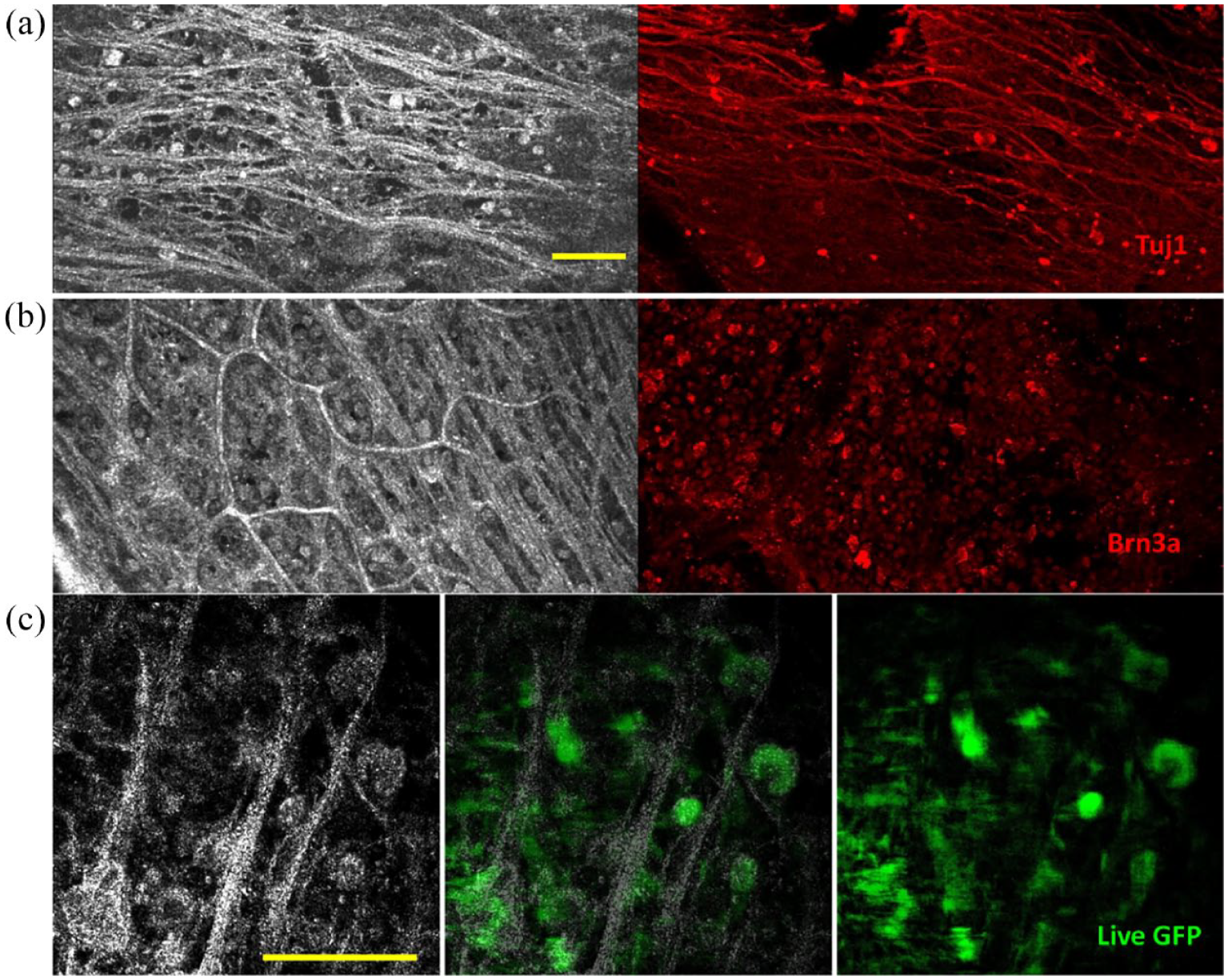
In vivo anterior human cornea images were obtained with FF-OCT and CM. (a) FF-OCT images of the anterior cornea at different depths. 1 – strong reflection on air–tear film interface, 2 – epithelium, 3 – SNP with nerves clearly seen, 4 – Bowman’s layer. (b) In vivo human corneal images of middle stroma, yellow arrows show the stromal nerves. (c) FF-OCT image of the posterior cornea. 1 – posterior stromal keratocytes, 2 – Descemet’s membrane; 3 – endothelium. A nerve is shown by the red arrows. (d, f, and h) zoomed areas (300 µm × 300 µm) of (a), (b), and (c). (e, g, and i) Confocal microscopy images (300 µm × 300 µm) of the same area of (d), (f), and (h). Republished from the study by Mazlin et al. 70
Corneal and retinal imaging also introduced unique challenges compared with ex vivo imaging. The difference between the refractive indexes of air and the eye introduced an optical mismatch between the interferometric arms. More precisely, when imaging inside the sample, the DOF was extended deeper in the sample (due to Snell’s law) and was not matching to the location of the sectioned slice, resulting in a loss of the signal. This problem was particularly critical for corneal imaging, as the microscope objective in the sample arm had high NA and small DOF (while the NA for the retinal imaging was smaller, determined by the diameter of the pupil of the eye). This problem called defocus was well known before the study by Blavier et al. 72 and had a solution – the deeper the DOF inside the sample, the more the reference arm of the interferometer should be extended to recover the optical matching. Corneal imaging could be achieved by pre-setting the reference arm position to the slice of interest (for example, endothelium). The eye was moving randomly axially and occasionally ending up in the position where the focus was also at the endothelium layer, thus producing a tomographic image. The influence of axial eye motion can be corrected by some methods, including correction algorithm or hardware improvement.73,74 TD-FF-OCT chose the latter to correct axial eye movement by combining SD-OCT.
The first combined TD-FF-OCT + SD-OCT system was introduced by Xiao et al. 75 with the purpose to locate the retina through the SD-OCT cross-sectional image. This was important because retinal signals in a single TD-FF-OCT image were too low. A high-quality retinal image can be reconstructed from a stack of TD-FF-OCT images; however, one can acquire a stack only once per several seconds to ensure light safety. SD-OCT can provide information about the retinal position in real time without turning on TD-FF-OCT. Only when the retina is in the correct position, the user turns on the TD-FF-OCT illumination and collects the stack of images (Figure 8).
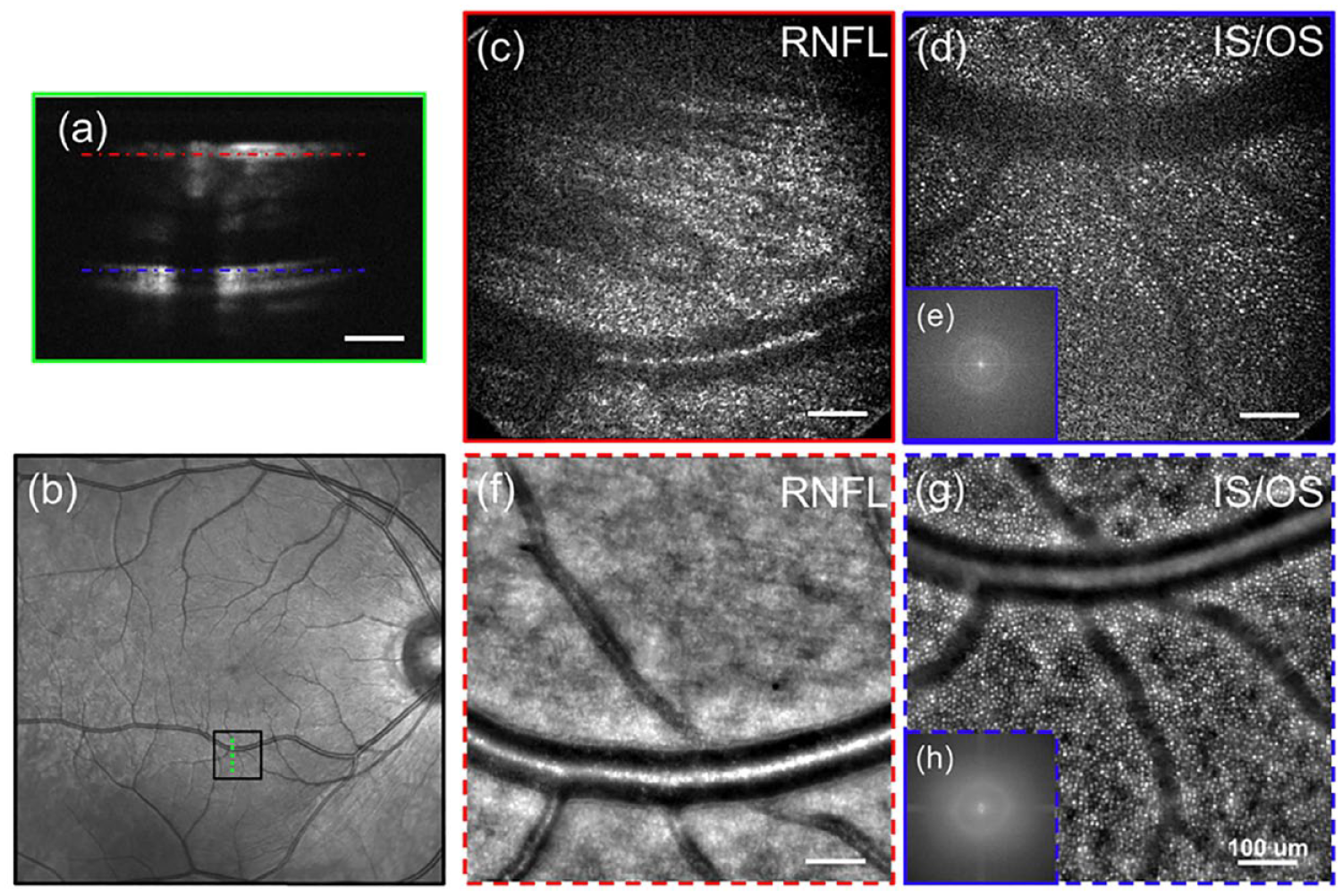
In vivo human retinal imaging by (c, d) FF-OCT compared with (f, g) AO retinal camera of the near periphery at 6° eccentricity. (a) The SD-OCT cross-sectional image of the imaging position with the red (RNFL) and blue (IS/OS) dashed lines indicates the FF-OCT imaging depth. (b) Fundus photography with the black box indicating the FF-OCT imaging area and the green dashed line showing the SD-OCT scanning position. In vivo FF-OCT image at 6° inferior to the fovea at the (c) RNFL and (d) IS/OS photoreceptor layer without AO. (e) The 2D power spectra of (d) show the Yellot’s ring, the radius of which is related to the cone photoreceptor spacing. The AO retinal camera image around the (f) RNFL and (g) IS/OS photoreceptor layer at the same retinal location, and (h) the 2D power spectra of (g). Scale bar: 100 μm. Republished from the study by Xiao et al. 71
The two devices have shown that TD-FF-OCT can obtain cell resolution images in the live human eye. In the cornea, one could resolve tear film reflection, epithelium, few micrometer-thick sub-basal nerves, Bowman’s membrane, 15 µm keratocyte cell nuclei in the stroma, Descemet’s membrane, and 20 µm hexagonal endothelial cell mosaic. Although corneal imaging with detail was possible using clinical in vivo confocal microscopy, TD-FF-OCT provided additional benefits of non-contact operation as well as larger FOV (~16 times in terms of area). In the retina, TD-FF-OCT resolved retinal nerve fibers as well as individual photoreceptors. It is particularly curious that this level of detail was achieved without using any correction of ocular aberrations that typically degrade the images even from healthy eyes. Xiao et al. 76 exposed this phenomenon, their study showed that full-field interferometry with incoherent illumination is less sensitive to optical aberrations compared with conventional microscopy. More precisely, the symmetric optical aberrations are less detrimental to the resolution but reduce the signal. This effect was later studied by Blavier et al. 72 and Barolle et al. 77 The latter rigorous publication has shown that the spatial incoherence of the illumination acts as a virtual confocal pinhole in TD-FF-OCT and its imaging performance is equivalent to a scanning time-gated coherent confocal microscope (CM). Thus, TD-FF-OCT had nearly twice the resolution of standard imaging at a moderate aberration level. It has shown to be particularly robust to low-order symmetric aberrations (such as defocus).
Improving in vivo TD-FF-OCT: real-time, high-signal, and large FOV imaging
Next efforts largely focused on making TD-FF-OCT imaging reliable to be more suitable for clinical studies in patients. Mazlin et al. 78 improved the combined TD-FF-OCT + SD-OCT device above by making an automatic corneal position tracking with SD-OCT and fast defocus correction with a voice coil motor in the reference arm. The device could correct eye movements at 50 Hz with a correction error of about 10 µm, producing images from the cornea in real time. No manual layer-by-layer correction was needed. The new device also simplified imaging of the other anterior eye layers. In limbus, it could resolve the palisades of Vogt, a hosting area for stem cells of the eye, as well as view and quantify the blood flow (angiography). Tear film could be clearly seen and its flow velocity could be quantified – a potentially important biomarker for spread-in-population dry eye disease.
The same principle of eye tracking with SD-OCT and correction with a voice coil motor in the reference arm was adapted by Mecê et al. 79 for retinal imaging. However, the difference is that the correction was not used for defocusing (required in the cornea), but for fixating on a single retinal layer. Prolonged acquisition from the same retinal layer could be averaged in time to improve SNR.
From the signal standpoint, single TD-FF-OCT images contained enough signal to resolve all corneal layers; however, signals in the single retinal images were weak (due to the smaller number of back-scattered ballistic photons from the retina as well as the smaller NA provided by the eye) and required heavy averaging. Scholler et al. 80 implemented an additional compact defocus-correcting lens that allowed to considerably improve the retinal images.
Another recent direction of work focused on improving the FOV. From the start, TD-FF-OCT systems provided a relatively large FOV of about 1 mm, which was on par or better than other cell-resolution clinical machines (for example, in vivo confocal microscopy; Figure 9).81–85 However, due to the curvature of the cornea, this FOV was sectioning through several corneal layers at once, effectively reducing the visible FOV of each individual layer. Mazlin et al. 86 adapted the shape of the optical sectioning field to the shape of the cornea by installing the curved lens into the reference arm. This allowed unprecedented FOV of the corneal sub-basal nerve and endothelial layers. Much more nerves and cells can be counted potentially leading to a more precise quantitative diagnosis of corneal conditions.

A: Curved-field OCT imaging of the SNP and endothelium in the human cornea in vivo. By matching the curvature of optical sectioning with the curvature of the cornea, CF-OCT substantially increases the FOV of the corneal endothelial layer. All scale bars are 0.1 mm. Adapted from the study by Mazlin et al. 86 B: Adaptive-glasses time-domain FF-OCT for wide-field high-resolution retinal imaging, the highest three-dimensional (3D) resolution possible in in vivo retinal imaging is achieved by combining optical coherence tomography (OCT) and adaptive optics. (a) 5° × 5° FOV FF-OCT retinal image, (b) 12° × 12° FOV image after stitching together five FF-OCT images. Zoomed areas of 1° × 1° FOV, chosen to be representative of different eccentricities, and their respective Fourier transforms are also shown. Adapted from the study by Scholler et al. 80
A similar approach to shaping the optical coherence gate was adapted by Mecê et al. 87 in retinal imaging. However, as the retinal curvature was smaller than that of the cornea, installing a glass plate was sufficient to flatten the retinal FOV.
Alternative holographic FF-OCT
Interestingly, in 2016, Sudkamp et al. 88 presented a full-field system that used a different approach to acquire en face images of in vivo human retina. Instead of acquiring several phase-shifted images in time, the mentioned approach captured them in a single shot using a holography-like approach. More precisely, the device used a fixed tilted reference mirror, a coherent super luminescent diode (SLD) light source to acquire the interference speckled pattern that, being filtered in Fourier domain, produced an en face section. By scanning the reference mirror, volumetric retinal images could be acquired. Simplicity is an undeniable advantage of the above method; however, it comes with a cost of reduced FOV (required for Fourier processing) and relatively low resolution (similar to the conventional clinical OCT).
Future directions of ophthalmic TD-FF-OCT
Matrix-based FF-OCT
Imaging through scattering cornea or crystalline lens presents a big challenge for ophthalmic diagnosis. Particularly so because the conditions leading to scattering are common in the population (for example, cataracts and corneal scarring). OCT and FF-OCT methods that discriminate ballistic photons from the multiple-scattering background are both negatively affected by the excessive scattering as it reduces the number of single-scattered photons. The smart OCT approach, which improves upon the TD-FF-OCT optical design, was introduced by Badon et al. 89 The method aims to overcome the multiple scattering problem by measuring the reflection matrix of the sample and then removing the multiple-scattering contribution through matrix processing. The reflection matrix is constructed by illuminating each first point of the sample and then detecting the photons from each second point of the sample (optionally first and second points can be the same). Although this method allows twice as much deeper imaging compared with OCT, substantial time is required for the acquisition and reconstruction of the reflection matrix. Therefore, today’s applications are limited to ex vivo studies.
Dark-field TD-FF-OCT
A series of publications by Auksorius and Boccara90,91 demonstrated dark-field TD-FF-OCT, where an opaque disk placed in the pupil plane was used to block the specular reflections and increase the tomographic image contrast. The results from the human fingerprint imaging suggest that this method can be also applied to gain imaging contrast in other in vivo tissues such as the human eye.
Dynamic in vivo TD-FF-OCT
Dynamic TD-FF-OCT mentioned above was limited to ex vivo studies. However, there is a great interest to apply the method to in vivo eye, thus gaining not only the light scattering OCT contrast but also physiological information on how well the different layers of the eye function. Application of the dynamic method to in vivo eye is complicated by the movements of the eye that have a much greater amplitude than the desired intracellular movements. This task is seen as even more challenging if one remembers that the timescale during which the organelles move (tens of milliseconds to a second) 67 is long enough so that eye can move by many micrometers. 92 However, there is a hope that the acquisition of a long stack of TD-FF-OCT images from the same ocular layer coupled with sophisticated 3D image processing may give access to dynamic information. In 2019, Scholler 93 showed that singular value decomposition (SVD) processing of the stacked TD-FF-OCT images can suppress the breathing and heart-beat artifacts when imaging in vivo mouse liver. In this study, the mouse was anesthetized and attached to the water immersion microscope objective via the vacuum pump to suppress the movements. Application of this method to freely moving in vivo human eye will require substantial progress in both the imaging and processing parts.
Discussion
TD-FF-OCT is likely to have a significant impact on future ophthalmic imaging due to its non-contact, wide-field, and cellular-resolution nature. Indeed, the demand for en face imaging inspires extensive research to improve the speed of classical scanning OCT. Traditional OCT needs to obtain 3D images to retrieve en face views. However, even the fastest scanning OCT system is unlikely to reach en face imaging speed of TD-FF-OCT any time soon.
Therefore, in the en face view, compared with the traditional scanning OCT, the TD-FF-OCT will have fewer motion artifacts and higher time accuracy to monitor the dynamic process. With swept-source laser, Fourier-domain FF-OCT (FD-FF-OCT; or the so-called full-field swept-source OCT) has also been developed achieving fast cellular imaging speed in both corneal and retinal imaging, however, suffers cross-talk noise that could degrade the image quality.30,94–96 Nevertheless, compared with Fourier-domain OCT techniques, TD-FF-OCT has relatively lower sensitivity. There are other excellent cellular imaging systems in the field of ophthalmic imaging. CM has been applied for cellular corneal imaging, which has improved the understanding of human corneal structure and pathophysiological mechanisms associated with various corneal diseases.82,83 However, its contact nature and the use of surface anesthetics and viscous gels during the examination may not only pose a risk of infection, but may also lead to changes in the corneal surface. 85 Adaptive optics (AO) assisted imaging systems such as AO retinal camera or AO-OCT-induced AO module for ocular aberration correction, achieving cellular resolution in human retinal imaging,97,98 but the system complexity and stability have limited their wide use in ophthalmic clinics. Table 1 summarizes the parameters and characteristics of representative ophthalmic imaging modalities.
Comparison of TD-FF-OCT with other systems in in vivo imaging.
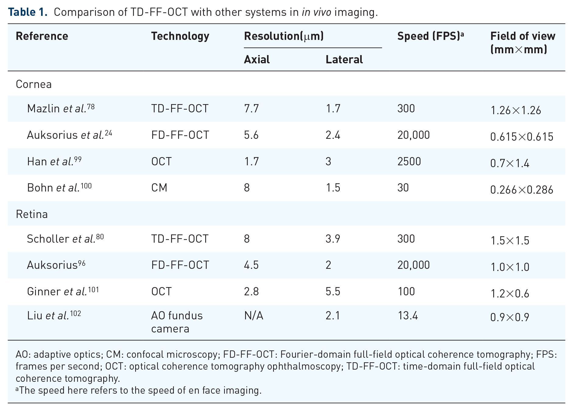
AO: adaptive optics; CM: confocal microscopy; FD-FF-OCT: Fourier-domain full-field optical coherence tomography; FPS: frames per second; OCT: optical coherence tomography ophthalmoscopy; TD-FF-OCT: time-domain full-field optical coherence tomography.
The speed here refers to the speed of en face imaging.
Conclusion
In conclusion, through the non-invasive, wide-field planar imaging, the improvement of FF-OCT will improve our understanding of human eye physiology and pathology. The ultra-high axial resolution, lateral resolution, and three-dimensional imaging mode make FF-OCT more accurate in detecting the pathophysiological changes of the eyeball, which has great potential for basic and clinical application in ophthalmology.