
Abstract
The main objective of this study is to investigate the electrical properties of Sn–3.0Ag–0.5Cu solder joint with the incorporation of carbon nanotube instead of solder bulk. Sn–3.0Ag–0.5Cu solder paste with the incorporation of carbon nanotube up to 0.04 wt% was fabricated by using mechanical mixing method. Fabricated solder pastes were then soldered on printed circuit board via reflow soldering at 260°C peak temperature. Electrical resistivity of Sn–3.0Ag–0.5Cu-carbon nanotube solder joints was measured by the four-point probe method at room temperature. Microstructure properties were observed by optical microscope and field emission scanning electron microscope. Electrical resistivity of Sn–3.0Ag–0.5Cu solder joint was found to increase with the incorporation carbon nanotube up to 0.03 wt% and slightly decrease at 0.04 wt%. Incorporation of carbon nanotube in the solder matrix apparently changes the microstructure of Sn–Ag–Cu solder alloys. Microstructural observation found that electrical resistivity correlated with the distribution area of eutectic phase in the solder matrix due to the existence of carbon nanotube. It was revealed that eutectic phase area increases with the increasing of carbon nanotube wt% up to 0.03 and then slightly decreases at the incorporation of 0.04 wt% carbon nanotube as parallel with the trend of electrical resistivity values.
Introduction
Soldering has become an important role in the electronics industry. Solders are used as a joining material to form a solder joint. The solder joint is used for electrical connection and mechanical bonding of the electronic component in packaging. 1 The performance of solders, therefore, plays a vital role in the overall functioning of the assemblies packaging. 2 As the move toward miniaturization in the electronic devices progresses rapidly, research concentrates on solder joint becomes a great interest. The growing trends of miniaturization increase solder joint reliability concerns. Size reduction generates higher heat densities inside the solder joint. Thus, may degrade solder joint reliability by the occurrence of fatigue due to the coefficient of thermal expansion mismatches. 3 In addition, generated heat may change the microstructures which lead to undesirable mechanical properties of solder joint. Numerous studies were conducted on mechanical properties of solder joint to enhance the mechanical strength of the solder joint. 4,5
Electrical resistivity, which is an inverse to the electric conductivity, is one of the important parameters to be evaluated other than mechanical and microstructural properties in soldering system. It is well known that the lower electrical resistivity exhibited a better flow of electric conductivity even in the solder joints interconnection of electronic devices. The attention on the solder joint in electrical connection is conceded to measure the extend of the reliability in terms of functionality and the flow current to electrical devices. Although it is noted that electrical resistivity in solder bulk and solder joint may vary in terms of structure, properties, and performance. Be that as it may, there seems to have less attempt research on accessing reliability in terms of electrical resistivity of solder joint. 5,6 In solder joint, it relies on the type of solder, substrate, and processing parameters of soldering. 5 For instance, the current technology in bold grid array use solder ball that can be widely found in surface mount technology (SMT) and wave soldering. They used solder paste, solder alloy, and flux in SMT technology, whereas in wave soldering, utilized molten solder.
Generally knows that Sn–Ag–Cu lead-free solder is considered as the most promising replacements for Sn–Pb solder due to its excellent properties. 7 However, many studies were done to overcome the excessive growth of the improvement of intermetallic compound (IMC) layer of Sn–Ag–Cu solder joint which leads to its brittleness and to improve mechanical properties of joining. One of the fortunate approaches is by incorporation of nanoparticles such as metallic or non-metallic into the solder system. 8 Carbon nanotube (CNT) is an amazing nanoparticle that has superior properties such as high strength, good thermal, and good conductivity. Incorporation of CNT in the composite-based materials was known effectively improved the mechanical and electrical properties of that composite. Adding or mixing CNTs to different matrix materials may change and enhance the functional in particular, the electrical properties of the formed CNT nanocomposite. Considering these aspects, CNT-based nanocomposites may find different potential technological applications. 9 –12 There are numerous works studied on solder system with CNTs that showed the IMC layer growth and the mechanical properties. 13 –15 While concerning on controlling the IMC layer growth and expand the integrity of solder joint, electrical properties of solder joint supposedly not to be neglected due to the main functionality. Many researches have been conducted to evaluate the electrical properties of solder alloy incorporated with nanoparticles. Babaghorbani et al. 16 reported the electrical resistivity of Sn–3.5Ag–0.7Cu and Sn–3.5Ag with incorporated of SnO2, Cu, Y2O3 + 8 mol% Y2O3, and TiB2. They found that reinforcements at nanometers length scale, metallic or ceramic, not affect the electrical resistivity compared to at micron length scale reinforcements which affect electrical resistivity adversely. Yakymovych et al. 17 revealed that the addition of minor Co nanoparticles into the SAC387 solder matrix have an insignificant effect on electrical resistivity, meanwhile the addition of 1 wt% Co nanoparticles apparently increase the electrical resistivity of SAC387 solder alloy. Only a few researchers reported on electrical properties of Sn–Ag–Cu (SAC) incorporated with CNT. Nai et al. 18 reported that incorporated of CNT with different weight percentages up to 0.07% into the SAC387 solder alloy do not degrade the electrical performance of that solder. They stated that it is attributed to the low volume fraction of porosity found in the solder incorporated by CNT.
In this research, the electrical resistivity of Sn–3.0Ag–0.5Cu (SAC305) solder joint with the incorporation of CNT up to 0.04 wt% were investigated by the four-point probe method. The role of CNT in this research is to produce the composite solder, which is the intention to improve the structural integrity and as well to maintain the solder properties such as wettability and solderability included electrical properties. In application, solder joint involving the chemical reaction of solder and substrate instead of solder bulk alloy. Therefore, it is very important to evaluate the electrical properties of the solder joint as compared to solder bulk alloys. This is due to the nature of reaction as well as industrial practices compliance.
Experimental procedure
In this study, SAC305 solder powder (20–38 µm size), no-clean flux, and multi-wall CNT with diameter 10–20 nm were used as raw materials. Solder powder and no-clean flux were supplied by Red Ring (M) Sdn. Bhd. (Selangor, Malaysia); meanwhile, CNT was imported from Cheap Tubes Inc., Grafton, Vermon, USA. Solder pastes SAC-CNT were manufactured by mix the SAC305 solder powder alloys with 0.01, 0.02, 0.03, and 0.04 by weight percentage of CNT. Solder powder alloys with the addition of different weight percentages of CNT and flux were mechanically mix and stir in a vacuum condition for about 2 h to get homogenous dispersion of CNT in the solder matrix. Fabricated solder paste namely as SAC305 as control solder, SAC305-CNT0.01, SAC305-CNT0.02, SAC305-CNT0.03, and SAC-CNT0.04 with corresponding to the CNT by weight percentage, respectively.
Soldered samples were prepared by manually stencil printing the solder paste on printed circuit board (PCB) with Cu surface finish. Printed solder pastes then go through the soldering process using the reflow oven. Peak temperature was set up at 260°C. Soldered samples were then cooled under room temperature (25°C). Figure 1 shows soldered samples on the PCB board. After that, soldered samples go through metallography process were included samples grinding using silicon carbide paper with the grit 340, 600, 800, and 1200 followed by polish using diamond paste with the size of 1 µm and 0.25 µm.
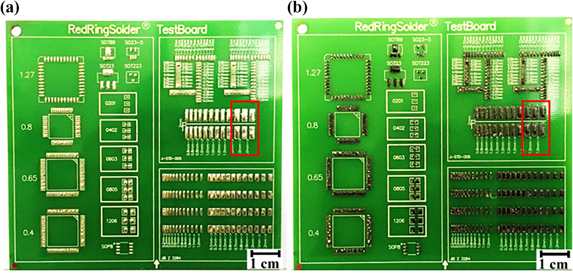
Soldered samples of (a) SAC305 solder and (b) representative SAC305 solder with 0.04 wt% CNT. SAC305: Sn–3.0Ag–0.5Cu; CNT: carbon nanotube.
Electrical resistivity of cross-sectioned samples was measured by using four-point probe machine. The measurement was carried out by touch the surface materials with four probes as illustrated in Figure 2. Figure 2 also displayed a simplified circuit diagram for four-point probe system that was used to measure electrical resistivity. Two probes were used to supply the electric current; meanwhile, the other two probes were used to measure the voltage. Using four probes can eliminate measurement errors due to probe resistance, spreading resistance under each probe, and contact resistance between each metal probe and the material.
19
In this study, four-point probe equipment used to measure the resistance of investigated solder joint is Jandel brand from the United Kingdom. Electrical resistivity test was carried out at room temperature. Test was performed at an applied current of 100 mA. Four measurements were taken for each sample. Since the thickness of sample is greater as compared to the distance between the probes, the following equations were used for the measurement of electrical resistivity. Schematic of electrical resistivity measurement and circuit diagram using four-point probe.
20


where A represents the cross-sectional area of the specimen, dx is the differential distance, and x is the distance from the outermost probe. By integrating the middle probes where the voltage is measured, the resistance can be expressed as

Hence, the bulk resistivity can be calculated by using the following equation

Microstructural analysis was carried out using Raxvision optical microscope and field emission scanning electron microscope (FESEM) Carl Zeiss brand Model Gemini SEM 500 available at Centre for Research and Innovation Management (CRIM), UKM, Malaysia. Before went through microstructural analysis, the samples were etched with the mixture etchant contains 2% hydrochloric acid, 5% nitric acid, and 93% methanol. Analysis of microstructure phase was done using Image J (software version 1.53e).
Result and discussion
Figure 3 shows the electrical resistivities value of SAC305 solder joints at room temperature with the incorporation of CNT up to 0.04 wt%. As can be seen, CNT addition affects the electrical resistivity of investigated solder joints. Electrical resistivity gradually increases with the increase of CNT addition up to 0.03 wt% and then slightly decreases at 0.04 wt% CNT. SAC305-CNT0.03 solder joint has the highest value of electrical resistivity which is 1.34 × 10⁻⁶ Ωm compared to the SAC305 solder joint which has the lowest value of electrical resistivity. It is well known that CNT has lower resistivity property compared to the SAC305 solder alloy elements such as Sn, Ag, and Cu. 21,22 Nevertheless, the incorporation of CNT in the solder did not decrease the electrical resistivity of the SAC305 solder joint as attained in this research. Several factors contribute to the electrical resistivity of composite solder alloys. Electrical resistivity for composite material was influenced by the following combination factors such as the volume fraction, the shape, the size and type of reinforcements, and matrix. Based on Matthiessens theory, the total electrical resistivity of material depends on the sum of the components, which are impurity, thermal, and deformation. 23 In this case, the existence of CNT in the solder matrix resulted in the disturbance of normal motions of electrons which is primarily attributed to lattice and impurity scattering. The presence of lattice imperfections due to the existence of CNT reduces the mean-free path of electron motion. This consequently leads to a reduction in electron mobility and hence increases the resistivity values. 24 Additionally, an increase in electrical resistivity of the SAC305 solder joint could be explained by microstructure changes due to the incorporation of CNT in the solder alloy. Structure properties of the solder alloys such as the type of matrix and intermetallic phase, the volume fraction of the intermetallic phase, and the sizes of intermetallic phase become the factors that may contribute to an increase in electrical resistance. Presence of intermetallic phase, second phase, and particles in the solder matrix may contribute to the lattice strain scattering. Lattice strain scattering leads to the disturbance of normal motion of electrons and resulted in increasing the electrical resistivity of solder alloy. 25

Electrical resistivity of SAC305 and SAC305-CNT. SAC305: Sn–3.0Ag–0.5Cu; CNT: carbon nanotube.
Figure 4 shows the FESEM micrograph with the energy-dispersive X-ray (EDX) mapping of the SAC305 solder joint. The microstructure of SAC305 solder joint consisted of primary β-Sn phase and the eutectic phase which contained the β-Sn phase with the distribution of very fine Ag3Sn IMC particles and needle-like Cu6Sn5 IMC. 26,27 Additionally, Figure 5 shows the FESEM micrograph with the EDX mapping of SAC305 with the incorporation of 0.04 wt% CNT. From the EDX mapping, CNT represents by the carbon element was observed distributed uniformly across the solder matrix. Kumar et al. 28 reported that CNT was distributed across the solder alloys and located especially at the grain boundary or the corner of Ag3Sn precipitates. It is known that CNT did not react with the elements in the SAC305 solder matrix to form some stable intermetallic compound. 29 However, the microstructure of SAC305 solder joint was found to have been changed due to the incorporation of CNT. From the EDX mapping, the SAC305-CNT0.04 solder matrix indicates a broad distribution area of the eutectic phase compared to the SAC305 solder.
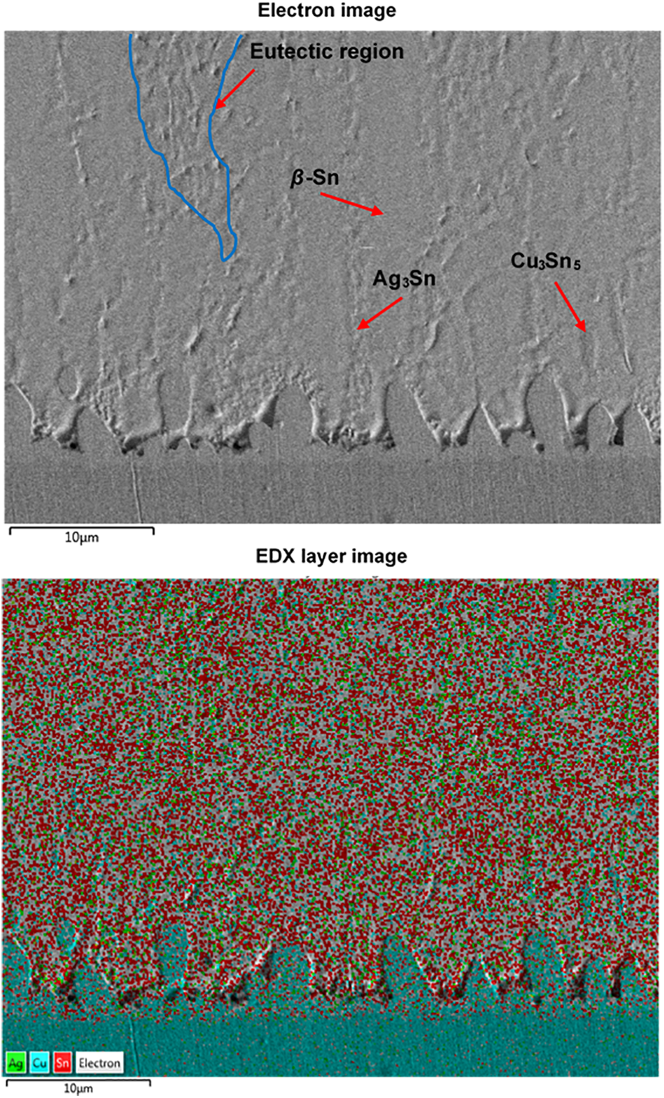
FESEM element mapping of SAC305 solder alloy. FESEM: field emission scanning electron microscope; SAC305: Sn–3.0Ag–0.5Cu.

FESEM element mapping of SAC305-CNT0.04 solder alloy. FESEM: field emission scanning electron microscope; SAC305: Sn–3.0Ag–0.5Cu; CNT: carbon nanotube.
Figure 6 shows the optical images of SAC305 and SAC305-CNT microstructure with different weight percentages of CNT, respectively. Distribution of eutectic phase area in each solder matrix was measured by using Image J software analysis to determine the effect of CNT toward the changes of microstructure. Figure 7 shows the eutectic phase area values of each investigated solder joints. The eutectic phase area of SAC305 solder joint was increased with the increasing of CNT up to 0.03 wt% and then slightly decreased with the incorporation of 0.04 wt% which have similar trend with the electrical resistivity values. Therefore, electrical resistivity of SAC305 solder joints with the incorporation of CNT correlate with the distribution of eutectic area phase in the solder matrix. FESEM micrograph of SAC305 and SAC305-CNT0.04 solder joint as shown in Figure 8 found that the eutectic area with the presence of CNT in the solder matrix is finer compared to the eutectic area without the existence of CNT. Finer structure of eutectic area increases the electrical resistance by reducing the mean-free path of electron motion. Reduction in electron mobility increases the electrical resistivity values. 25 Refinement of SAC solder microstructure by incorporation of CNT has also been reported by previous researcher. 30
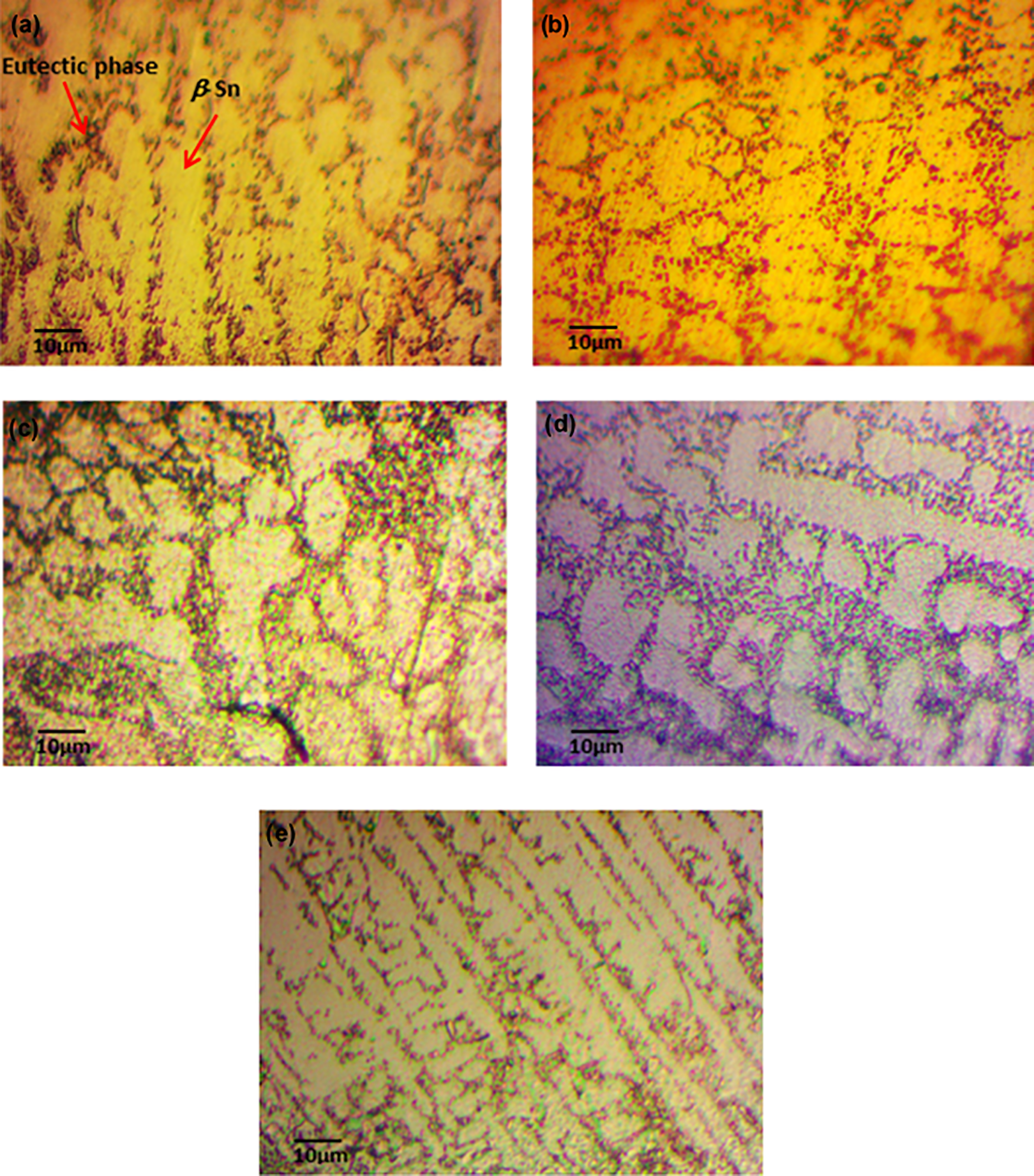
Microstructure of SAC305 with different weight percentages of CNT: (a) SAC305, (b) SAC305-CNT0.01, (c) SAC305-CNT0.02, (d) SAC305-CNT0.03, and (e) SAC305-CNT0.04. SAC305: Sn–3.0Ag–0.5Cu; CNT: carbon nanotube.

Eutectic phase area values of each investigated solder joint.

FESEM micrograph of SAC305 and SAC305-CNT0.04 focus on the eutectic area. FESEM: field emission scanning electron microscope; SAC305: Sn–3.0Ag–0.5Cu; CNT: carbon nanotube.
In this current work, incorporation of CNT up to 0.03 wt% increases the electrical resistivity of the SAC305 solder joint and then it slightly decreases at 0.04 wt% of CNT. It shows that electrical resistivity changed with the amount of CNT addition. However, decreasing electrical resistivity at 0.04 wt % is believed due to the high volume of CNT in the solder matrix tends to agglomerate and squeeze out with the flux during the soldering process. CNT was expelled out to the outer surface because of different densities between CNT and metallic SAC alloys. 31,32 Therefore, the amount of CNT existence in the solder matrix influences the electrical resistivity. Microstructural observation in Figure 9(b) indicates the CNT layer formed at the outermost of the SAC305-CNT0.04 solder bump. It proved that CNT was floated and expelled out during the reflow soldering process. Furthermore, SAC305 solder bump indicates no layer formed in Figure 9(a).

Micrograph of (a) SAC305 without forming layer and (b) SAC305-CNT0.04 with the forming of CNT layer cover-up on top of the solder bump. SAC305: Sn–3.0Ag–0.5Cu; CNT: carbon nanotube.
Table 1 presents the electrical resistivity of SAC305 solder with the addition of CNT and other nanoparticles conducted by previous researchers. Based on the results, it proves that the existence of impurities in the solder matrix will increase the electrical resistivity as follow the Matthiessen theory. 33 Comparison of current work with Nai et al. 18 revealed that electrical resistivity of the SAC305-CNT solder joint is higher compared to the electrical resistivity of SAC305-CNT solder bulk. Different values of electrical resistivity by addition of CNT are mainly due to the form type of solder, types of CNT used, and the processing methods used. Therefore, it is essential to focus on solder joint electrical properties instead of solder bulk. This is due to many considerations need to be taken in solder joining. In a real application, using solder as joining material involved the chemical reaction between the solder and the substrate. During the soldering process of the solder joint, it involved the flux reaction, which is part of the solder to assist the formation of joining. 34 The reaction of flux with CNT in the solder joint significantly influences the amount of CNT existence in the solder matrix. Hence, the amount of CNT in the solder matrix affected the electrical resistivity of solder joint.
Electrical resistivity of Sn–Ag–Cu solder with the addition of CNT and nanoparticles.

SAC305: Sn–3.0Ag–0.5Cu; CNT: carbon nanotube.
Conclusion
Electrical resistivity SAC305 solder joint with the incorporation of CNT up to 0.04 wt% was successfully studied using four-point probe method. Electrical resistivity of SAC305 solder joint was influenced by the volume of CNT weight percentage. The addition of CNT was found did not degrade the electrical properties of the solder joint. Observation toward microstructure of SAC305-CNT was revealed that electrical resistivity values closely related to the distribution of eutectic phase in the solder matrix due to the existence of CNT. High distribution of eutectic phase increases the electrical resistivity of the SAC305 solder joint.
Footnotes
Declaration of conflicting interests
The author(s) declared no potential conflicts of interest with respect to the research, authorship, and/or publication of this article.
Funding
The author(s) disclosed receipt of the following financial support for the research, authorship, and/or publication of this article: This work was supported by Universiti Kebangsaan Malaysia (UKM) under MI-2018-019 and FRGS/1/2019/STG07/UKM/03/1 grant and Redring Solder (M) Sdn. Bhd. for research materials and collaboration work.