
Abstract
In this article, multiwalled carbon nanotube/natural rubber composites with resistance-strain sensitivity were prepared by solution method, when the electrical percolation threshold of multiwalled carbon nanotube is only ∼3.5 wt%. The mechanical properties and resistance-strain response sensitivity were studied and analyzed systematically. The dispersion of multiwalled carbon nanotubes in the natural rubber matrix was characterized by field-emission scanning electron microscope and X-ray diffractometer. The composite exhibits good deformation sensitivity (gauge factor >27), large strain sensing range (>200%), and high signal stability when multiwalled carbon nanotube content was appropriate. The composite is suited to application in strain monitoring of large deformation structures since the resistance-strain response is more stable when strain exceeds 100%. To understand the mechanism of the resistance-strain response, the ‘shoulder peak’ of resistance-strain curve was researched and explained by the digital image correlation method, and an analytical model was developed when considering the effects of electronic tunneling and hopping in multiwalled carbon nanotube networks. Both experiment and analytical results confirm the break-restructure process of multiwalled carbon nanotube networks under applied strain cause the resistance-strain response. Finally, the practical application of the composite to monitoring strain load of rubber isolation bearing was realized.
Keywords
Introduction
Since the first application of isolation base technology in 1909, the rubber isolation bearing has been widely used in seismic protection systems because of its significant effect on improving the seismic resistance ability of buildings and constructions. 1,2 Meanwhile, long-term and real-time monitoring for the structural health of rubber isolation bearing is important to ensure the anti-seismic property and service safety of building structures. However, the traditional sensors with high brittleness, weak damage resistance, high maintenance cost, low service life, poor durability, and especially small strain range (∼5%) 3 –5 are not appropriate for the large deformable rubber isolation bearing. Therefore, nanofiller–rubber composites, which combine the properties with the high electrical conductivity of the nanofillers and flexible deformation characteristics of the rubber matrix, have the potential to meet the requirements for the bearing health monitoring. 6 –8
Carbon nanotubes (CNTs), which are used to fill polymer composites, have attracted much research attention in recent years due to high specific surface area, high aspect ratio, excellent electrical properties, 9 –11 electromagnetic shielding properties, 12 and good free radical scavenging ability. 13 However, the issues of dispersion and interfacial interaction between CNTs and matrix are still a problem that limits their application. To overcome these issues, Basiuk et al. 14 proposed a fast and efficient solvent-free functionalization method of buckypaper (BP) mats prefabricated from oxidized multiwalled carbon nanotubes (MWCNTs) treated in strong acid and surfactant and found that the stability of BP in water increased dramatically. Kalakonda et al. 15 performed solution-based fabrication method to overcome the aggregation of nanotubes and improved nanocomposites mechanical properties prepared by backfilling of preformed hydrogel and aerogels of individually dispersed MWCNTs and thermoplastic polyurethane. Though the dispersion has been explored as above, and the different synthetic methods of CNTs, such as the arc discharge, 16 pulsed laser deposition, 17 and chemical vapor deposition, 16 can also alleviate the abovementioned problems, it was still difficult to balance the relationship between dispersion, mechanical properties, and conductivity of composite, and it is hard to maintain intrinsic properties of CNTs.
As mentioned above, nanofiller–rubber composites are appropriate for health monitoring for rubber isolation bearings since the wonderful compatibility, and rubber is a widely used material in construction engineering. 18,19 The most prevalent rubber materials applied in isolation bearing are nature rubber (NR) and butadiene rubber (BR). The nanocomposite with NR and BR matrices is also widely researched. For instance, Wang et al. 20 modified NR filled with high content of silicon by reduced graphene oxide and prepared silicon/graphene/NR composites with excellent comprehensive performance, which played a promoting role in the application of rubber tires. Sancaktar and Basan 21 studied the dispersion of carbon black (CB) in NR and BR, compared the conductive properties of CB/NR and CB/BR composites, and found that CB/BR has higher conductivity than CB/NR. Saberian et al. 22 used response surface methodology to investigate the effects of multiple factors on the mechanical properties of epoxy/graphene nanoplatelets/carboxylated nitrile BR composites, and the optimum value of graphene nanoplatelets and carboxylated nitrile BR with optimal mechanical properties was determined. They showed that the presence of 10 wt% of carboxylated nitrile BR in the epoxy matrix increased the elongation at break by the considerable amount of ∼49%. França et al. 23 prepared an elastic conductive material by melting method based on nitrile rubber and polypyrrole (PPy) and confirmed the enhancement of electrical conductivity and mechanical properties caused by the three PPy fillers on the composites.
The strain sensors used for strain monitoring require good sensitivity, large strain, and stable repeatability. Liu et al. 24 used a simple and effective method to prepare NR/graphene composite with strain ∼3% and the GF 46, but the effective strain range was less than 20%, which was suitable for human pulse monitoring. Yang et al. 25 prepared the CB/CNT/thermoplastic elastomer composite, GF was only ∼7.5 when the strain was 20%, and GF tends to decrease with the increase of strain. Chen et al. 26 investigated the electrical conductivity of isoprene rubber/CNT/CB composite with good durability (4850 cycles) and high sensitivity, which was suitable for detect human motions and emotional expressions. Zheng et al. 27 prepared CNT/thermoplastic polyurethane composites, but GF was only 6.8 when a strain up to 135%. As well, Jiang et al. 28 prepared CNT/poly (M-phenylene isophthalamide) composites with strain 220% and the GF 5.4. However, it is still difficult to achieve large deformation and good sensitivity simultaneously, which is important for the sensors used in deformation monitoring of rubber isolation bearings. Meanwhile, NR composite sensors modified by CNTs and other nanomaterials, such as graphene, have been widely studied and applied in stretch electrical devices, 29 chemical sensing, environmental pollution detection, 30,31 and tires. 20 However, NR composites applied to structural deformation monitoring in civil engineering have been rarely reported, especially the deformation monitoring of rubber isolation bearing.
In this article, MWCNTs and NR were selected as raw materials to prepare the MWCNT/NR composites by solution method. The mechanical properties, conductivity, recovery properties, sensitivity, and stability of resistance-strain response were researched. The effects of the MWCNT contents and strain amplitude on the resistance-strain response of MWCNT/NR composites were analyzed, and the dispersion of MWCNTs in the rubber matrix was characterized by field-emission scanning electron microscope (FE-SEM) and X-ray diffractometer (XRD). It is clearly verified through the digital image correlation (DIC) method that the appearance of the ‘shoulder peak’ is related to the deformation capacity of the matrix. The mechanism of resistance-strain response was explained during the stretch processing by developing a mathematical model. The stability and sensitivity of MWCNT/NR composite materials are further confirmed by practical deformation monitoring for isolation bearing.
Experimental
Raw materials
Natural rubber latex (NRL) with 60 wt% solid content was purchased from Zhengmao Petrochemical Co., Ltd., Maoming City, Guangdong, China. MWCNTs with lengths of 10–20 µm, outer diameters of 4–6 nm, specific surface areas of 500–700 m 2 g−1, and purity of >98% were purchased from Chengdu Organic Chemicals Co., Ltd., China. Other agents including sulfur powder, zinc oxide, stearic acid, N-isopropyl-N′-phenylp-phenylenediamine, N-tert-butyl-2-benzothiazolidine, and tetrahydrofuran (THF) were obtained from Kunming Kerui Instrument Co., Ltd., China.
Preparation of the MWCNT/NR composites
In this work, MWCNT/NR composites were prepared by a solution method. First, the NRL and MWCNTs were dispersed in THF at room temperature, and ultrasonic dispersion and mechanical stirring were used for 2 h to obtain a stable NRL-MWCNT/THF suspension. Then, the other additives presented in Table 1 were mixed with the suspension, and ultrasonic dispersion and mechanical stirring were continued for 1 h. After removing the solvent by vacuum desiccation, the unvulcanized mixture was obtained, as shown in Figure 1(a). The mixture was finally vulcanized at 160°C for 20 min to prepare the MWCNT/NR composites with a smooth appearance and satisfactory strength, as shown in Figure 1(b). Table 1 indicates all materials used in this preparation process.
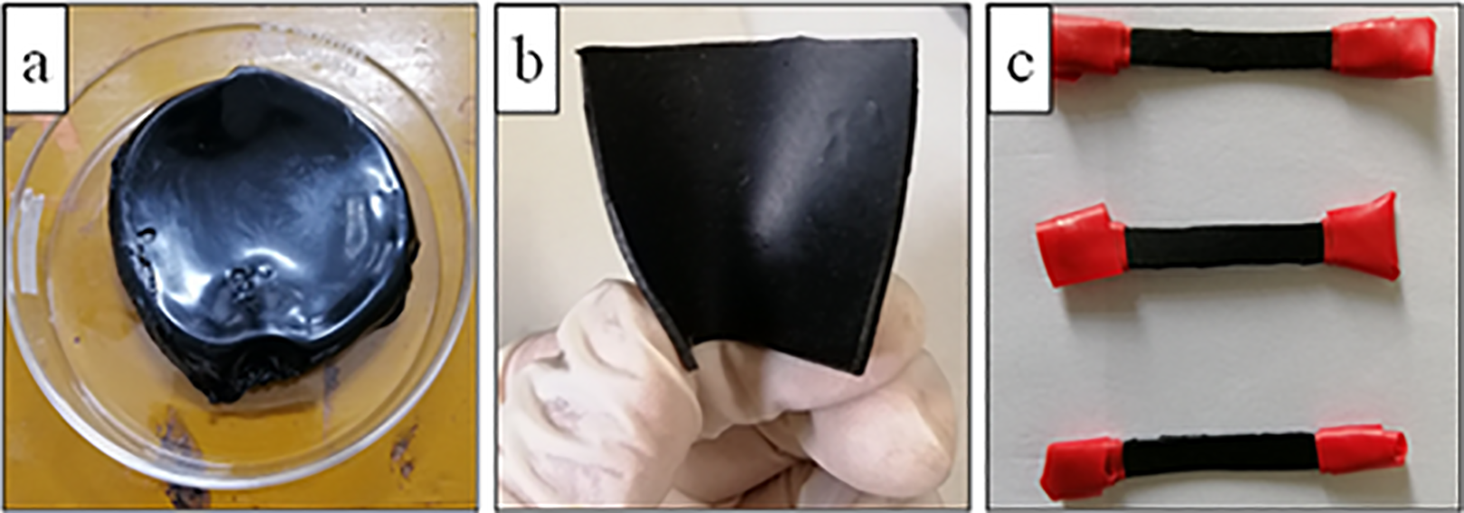
Photographs of samples: (a) specimen of an unvulcanized MWCNT/NR composite, (b) specimen of a vulcanized MWCNT/NR composite, and (c) sensor samples. MWCNT: multiwalled carbon nanotube; NR: natural rubber.
The formula of the MWCNT/NR composites (wt%).

MWCNT: multiwalled carbon nanotube; NR: natural rubber; NRL: natural rubber latex; ZnO: zinc oxide; SA: stearic acid; 4010NA: N-isopropyl-N′-phenylp-phenylenediamine; NS: N-tert-butyl-2-benzothiazolidine.
Characterization
SEM characterization
FE-SEM (NOVA Nano SEM450, the United States) was used to characterize the morphology of the MWCNT/NR composites at an accelerated voltage of 10 kV. Samples were frozen in liquid nitrogen for 5 min and then external forces were applied to break samples to obtain new fracture surfaces. Platinum-sprayed treatment was carried out on the fracture surface of the sample to improve the conductivity and obtain better FE-SEM images. In this work, composite samples with different MWCNT contents were tested.
XRD characterization
MWCNT/NR composites were detected by XRD at a scanning rate of 2° min−1 with 2θ ranging from 5° to 90° under Cu Kα radiation. In this work, samples with 0, 2, 6, and 8 wt% MWCNT contents were tested, and the dispersion of MWCNTs in NR was evaluated by comparing the variation of characteristic peaks of composites.
Mechanical property characterization
The mechanical property of the dumbbell standard specimens of MWCNT/NR was measured by a tensile and compression test system (WDW-10, Changchun Institude of Testing Machines, China) with a maximum load of 10 kN controlled by displacement at ambient temperature, and the loading rate was 200 ± 5 mm min−1 according to ISO 37:2005(E). The number of samples in each experiment was no less than three.
Conductivity test
To measure the electrical conductivity of the MWCNT/NR composite, the electrical signals (all sizes are 40 × 5 × 1 mm3) were measured with a Keysight 34410A device (Keysight Technologies, the United States) . The two-wire method was used to directly measure the resistance of the samples under unstrained conditions. A stabilized voltage source was used to provide a power source to measure the current change for the sample under a stretch–release cyclic load (Figure S1), and the resistance change was calculated according to Ampere’s law (I = U/R), where I represents the current, U represents the test terminal voltage of samples, and R is the resistance of test samples. The measurement length of the sample in the resistance response was 20 mm. To avoid electrical signal interference caused by the testing machine, the two clamping ends of the sample were wrapped with insulating tape, as shown in Figure 1(c). According to the resistance value, the volumetric conductivity of samples was calculated by combining equations (1)–(3).
The resistance and conductivity are directly related to the geometry of samples

where R is the resistance of the samples, t is the thickness, and A is the cross-sectional area. The conductance G has the following relation with resistance

Conductivity is defined as the current flowing through 1 cm3 of the material per unit potential. The relationship between the conductivity and conductance is shown below

where
Results and discussion
Characterization of the morphology
Figure 2 is FE-SEM micrograph of the MWCNTs. It is clearly seen that the MWCNTs present a large aspect ratio and a high degree of mutual entanglement.
FE-SEM micromorphology of the MWCNTs. FE-SEM: field-emission scanning electron microscope; MWCNT: multiwalled carbon nanotube.
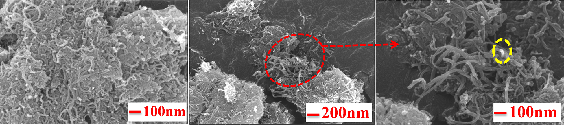
The uniform dispersion of nanofillers and the formation of stable conductive networks are two important factors affecting the conductive capability and resistance-strain response sensitivity of conductive polymer composites (CPCs). 32,33 Figure 3 shows the FE-SEM images of the MWCNT/NR composites with different MWCNT contents (2, 6, and 8 wt%).

FE-SEM micrographs of composites with different MWCNT contents: (a) 2 wt% MWCNTs, (b) 6 wt% MWCNTs, and (c) 8 wt% MWCNTs. FE-SEM: field-emission scanning electron microscope; MWCNT: multiwalled carbon nanotube.
According to the FE-SEM morphology of the MWCNTs in Figure 2 and related literature, 34,35 the white dots in Figure 3 represent the MWCNTs distributed in the NR matrix. It is clearly shown in the enlarged images. A large number of the MWCNTs are distributed homogeneously throughout the entire visible area (Figure 3(a″) to (c″)). However, the number of white spots for the 2 wt% MWCNT/NR composite in Figure 3(a) is much fewer than those for the 6 and 8 wt% MWCNT/NR composites as shown in Figure 3(b) and (c), respectively, and the spaces between the MWCNT clusters (Figure 3(a′)) are also much larger than the spaces of the 6 and 8 wt% MWCNT/NR composites (Figure 3(b′) and (c′), respectively), which indicate that the MWCNT networks and conductive pathways for 2 wt% MWCNT/NR composite are sparse and incomplete. Therefore, this may be the reason why the 2 wt% MWCNT/NR composite is not conductive. More details about the conductivity analysis are described in other parts of the article.
To further investigate the dispersion of MWCNTs in the NR matrix, XRD test was carried out, and the results are shown in Figure 4. There is no change for the characteristic peak of the MWCNT/NR composite when compared with that of the pure rubber material (2θ = 19.66°), and the characteristic peaks of MWCNTs (2θ = 25.70° and 43.14°) disappear. It is confirmed that the MWCNTs have good dispersion in NR and no obvious agglomeration by combining the FE-SEM results in Figure 3.

XRD spectra of MWCNT/NR composites. XRD: X-ray diffractometer; MWCNT: multiwalled carbon nanotube; NR: natural rubber.
Mechanical property
Figure 5 illustrates modulus at 100% strain and tensile strength of the composites when MWCNT contents change from 0 wt% to 6 wt%. It is firstly shown in Figure 5 that the MWCNT induces stiffness enhancement for composite since the modulus at 100% strain of the 6 wt.% MWCNT/NR composites dramatically increases to 1.57 MPa, which is increased by 149.2% compared with the neat NR (0.63 MPa). Thus the higher MWCNT content leads to more contact surface and powerful interfacial interactions and H-bonding effect between MWCNTs and NR, which induce the stiffness increasing of composite. 8,36,37 The tensile strength of the composite is also improved when MWCNT contents increase from 0 wt% to 3 wt%. However, the aggregation increases gradually when MWCNT contents beyond 3 wt%, which leads to reducing of tensile strength. 8

Summary of strength and modulus of MWCNT/NR as a function of MWCNT contents. MWCNT: multiwalled carbon nanotube; NR: natural rubber.
Conductive property
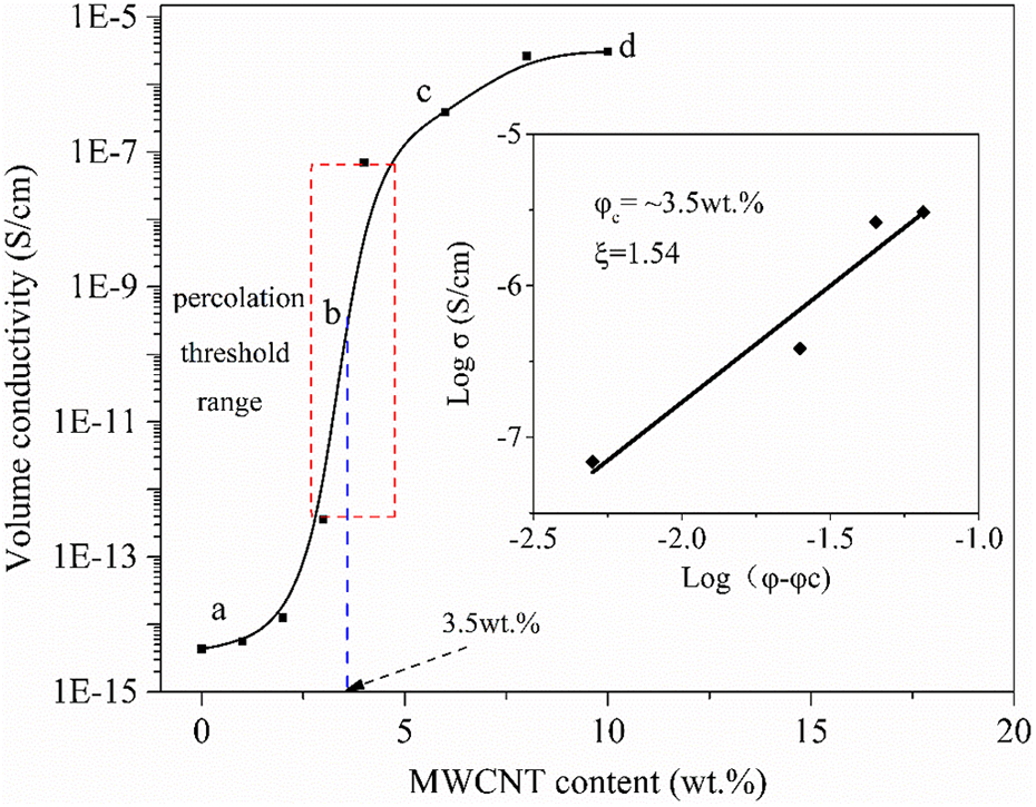
The influence of the MWCNT contents on the conductivity of composites is shown in Figure 6. The conductivity of the composite with 1 wt% MWCNTs at point a in Figure 6 is low, and the composite is insulated. However, the conductivity increases sharply when the content of MWCNTs exceeds 2 wt%. As shown in the red dot of Figure 6, the value of conductivity increased by ∼10 5 times when the content of MWCNTs changed from 3 wt% to 4 wt%.
Relationship of the conductivity via the MWCNT contents. MWCNT: multiwalled carbon nanotube.
This sharp increase of conductivity is defined as conductive percolation, the conductive network has been formed this moment, and the corresponding content of MWCNTs at point b in Figure 6 is called the percolation threshold.
38
After MWCNT contents exceed the threshold value, the conductive network is gradually completed and the conductivity

where
The percolation threshold
Behavior of the resistance-strain response
The resistance-strain sensing behavior of 6 and 8 wt% MWCNT/NR composites were investigated herein. Figure 7 indicates the curve of R/R 0 as a function of applied strain for the composite, where R 0 and R are the resistance of the specimen initial strain and stretch deformation, respectively. It is firstly seen in Figure 7 that the values of R/R 0 continue to increase with the increasing of applied strain. The conductivity of the composite depends on the number of electronic tunneling and hopping points in MWCNT networks. This number decreases when the space and distance between MWCNT molecules and clusters increase under stretch deformation and then the resistance increases. Furthermore, it is indicated in Figure 7 and the inset that the 6 wt% MWCNT/NR composite has a higher value of R/R 0 than 8 wt% MWCNT/NR composite at the same strain degree. The details of mechanism for resistance-strain sensing behavior are analyzed later.

R/R 0 via strain for composites with different MWCNT contents. MWCNT: multiwalled carbon nanotube.
To further quantitative investigate the sensitivity of the composites, the gauge factor

Maximum gauge factor versus the strain sensing range: comparison with the literature for flexible strain sensors (the references and the detail values of the data are presented in Supplementary Material).
Reliable strain sensing materials should not only have high sensitivity and large deformation ability but also need to have good stability. Figure 9(a) and (b) shows the response of R/R 0 under a cyclic dynamic strain with an amplitude of 200% and a strain rate of 1 mm s−1 for 6 and 8 wt% MWCNT/NR composites, respectively. As is seen, the values of R/R 0 keep synchronous variation with the cycle strain. By comparing Figure 9(a) and (b), the stability of 8 wt% MWCNT/NR composite is better. However, as with many literatures, 8,43 the ‘shoulder peak’ phenomenon is also observed in Figure 9(a) and (b). ‘Shoulder peak’ frequently appears during the unloading process in each strain cycle. The origin of the ‘shoulder peak’ has not been fully explained so far, but the main reasons focus on the competition between the destruction and the reconstruction of conductive networks and the viscoelastic plasticity of matrix materials. 9
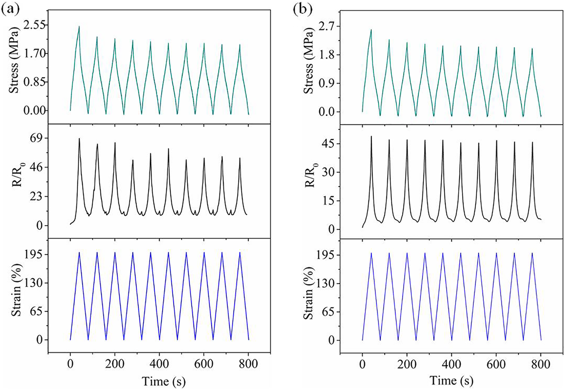
R/R 0 under cyclic strain for composites with different MWCNT contents: (a) 6 wt% MWCNTs and (b) 8 wt% MWCNTs. MWCNT: multiwalled carbon nanotube.
To explain the relationship between ‘shoulder peak’ and the deformation ability of MWCNT/NR, the strain distributions of the MWCNT/NR composites were investigated during the stretch–release cycle by the DIC method and illustrated by Figure 10(a) to (c). Comparison of Figure 10 shows that the strain of the composite failed to recover completely when the applied strain vanished. This hysteretic strain impedes the reconstruction of conductive network and leads to ‘shoulder peak’ phenomenon. Furthermore, the hysteretic strain for 6 wt% MWCNT/NR composites as shown in Figure 10(b) is more obvious than the 8 wt% MWCNT/NR composites as shown in Figure 10(c), and this is the reason why the ‘shoulder peak’ phenomenon for 6 wt% MWCNT/NR composites is more obvious than 8 wt% MWCNT/NR composites, as shown in Figure 9(a) and (b).

The MWCNT/NR strain analyzed via the DIC method under cyclic loading. (a) Initial stage of MWCNT/NR, released MWCNT/NR nanocomposites of 6 wt% MWCNT/NR (b) and 8 wt% MWCNT/NR (c) to the loading displacement zero. MWCNT: multiwalled carbon nanotube; NR: natural rubber; DIC: digital image correlation.
As illustrate in Figure 8, the GF value in this work is higher than some other composites. Herein, the resistance-strain response behaviors under dynamic strain with different amplitudes are further investigated. Figure 11 and Figure S2 show the R/R 0 and coefficient of variation of R/R 0 of the 6 and 8 wt% MWCNT/NR composites under dynamic strain with amplitudes of 5, 10, 20, 50, 100, and 200%, respectively. Both specimens with 6 and 8 wt% MWCNT/NR composites indicate the most stable and repeatable resistance-strain response under 200% strain amplitude. R/R 0 under lower strain amplitudes show downward drifting, especially when strain amplitudes are below 50%. It is further confirmed that the MWCNT/NR composite exhibits excellent resistance-strain response characteristics under large strain. Furthermore, the R/R 0 for 6 wt% MWCNT/NR composite are higher than 8 wt% MWCNT/NR composite at the same strain levels and the stability of R/R 0 for 8 wt% MWCNT/NR composite after several strain cycles is more satisfactory. The ‘shoulder peak’ of 6 wt% MWCNT/NR composite is also higher than 8 wt% MWCNT/NR at 200% strain amplitude. Moreover, the 6 wt% MWCNT/NR composite has better sensitivity when the 8 wt% MWCNT/NR composite indicates better stability.

The R/R 0 under cycle strain for composites with different strain amplitudes.
Mechanism of the resistance-strain response
As mentioned above, the strain sensing behaviors are induced by the tunneling and hopping effects in the MWCNT networks. To gain a clear understanding of the structure variation in the conductive network during loading cycle, Figure 12(a) to (d) presents the structure variation of the MWCNT conductive networks in the NR matrix during different strain cycle stages.

(a) to (d) Schematic diagram for the structural variation in the conductive network under the stretch–release cycle: contact points (blue circles), noncontact points (red circles), and new tunneling points (yellow circles).
As shown in Figure 12(a), the MWCNTs at the initial stage form a conductive network in the NR matrix. The blue circles in Figure 12(a) indicate the cross-link contacting points of different MWCNT molecules and the red circles highlight the noncontact points. However, the tunneling effect promoted the electron transmission when the distance between noncontact points highlighted by red circles satisfy tunneling conductivity condition. 35 Therefore, the conductive behavior of the MWCNT/NR composite is mainly caused by tunneling effect at the initial stage without strain, when cross-link contacting effect plays an auxiliary role.
The conductive networks are stretched with the applied strain increases, which leads to distance increasing between MWCNTs molecules (as shown in Figure 12(b)), and the number of noncontact points in red circles decreases when comparing with the initial stage in Figure 12(a). In this case, some new tunneling effect points are formed as marked by yellow circles, but the total number of such noncontact points decreases and tunneling effects are weakened. Thus, the resistance of composite is enhanced.
As shown in Figure 12(c), the MWCNT network is damaged when the strain is further increased. The number for noncontact points with tunneling effect and cross-link points with contacting effect both reduce, as highlighted by red and blue circles, respectively. Similarly, some new tunneling effect points are formed as marked by yellow circles. Therefore, the resistance of composite increases dramatically since both tunneling and contacting effects are greatly weakened and only hopping effect maintains slight conductivity. 35
During the unloading stage, the MWCNT network is reconstructed since NR matrix recovery and both noncontact points with tunneling effect and cross-link points with contacting effect are formed again, as shown in Figure 12(d). Since the reconstructed network is not perfected when comparing with the initial one, the resistance in the unloading stage decreases but remains higher than the resistance level at the initial stage. However, the destruction and reconstruction of MWCNT networks keep balance basically after several strain cycles, and the resistance of composite finally keeps stable as shown in Figure 9.
To better understand the behavior of the resistance-strain response, an analytical model is established according to the theory of tunneling and hopping effects. 25,35 As discussed above, the strain sensing behavior is divided into two distinct stages in the strain ε 0–200%. At the first stage (ε < 65%), tunneling effect plays a major role. Based on tunneling effect theory proposed by Simmons, 35,44 the resistance R is shown as a function of ε as follows

where
When the strain further increased to ε > ε 1 = 65%, the irreversible destruction of MWCNT networks is occurred and the hopping effect proposed by Mott is appropriate to explain the relation of strain and resistance. 35,45,46 Thus, we have the expression for R as following
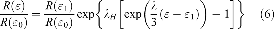
where
The R/R0 -strain curve of 6 and 8 wt% MWCNT/NR composites based on experiment test and analytical model of equations (5) and (6) are shown in Figure 13(a) and (b). The relative parameters in the present work are indicated in Table 2. As is shown in Figure 13, the theoretical model curves (domains 1 and 2) of 6 and 8 wt% MWCNT/NR composites are well-matched with the experimental results. Therefore, the rationality of analytical model is confirmed and the mechanism for resistance-strain sensing behaviors is investigated. Note that the strain of the composites can be gained according to the model of the domain when the resistance R(ε) of the composites is obtained through the experiment, which opens wide perspectives for ‘sensing‘ the mechanical structure of the composite by monitoring its electrical response.

Comparison of the developed theory with the experiment. (a) 6 wt% MWCNT/NR composite and (b) 8 wt% MWCNT/NR composite. MWCNT: multiwalled carbon nanotube; NR: natural rubber.

MWCNT: multiwalled carbon nanotube; NR: natural rubber.
Application for monitoring the rubber isolation bearing
The MWCNT/NR composite has been used to monitor the deformation of the rubber isolation bearing. Figure S3 indicates the experimental scheme. The 8 wt% MWCNT/NR composite sensor was firmly adhered on the lateral surface of isolation bearing, as indicated in Figure 14(a). The 34410A device was directly connected to the sensor to measure resistance. In the actual working environment, the bearing was sheared to realize the shock absorption and energy dissipation. Thus, both the stretching and recovery were the important factors to evaluate the bearing service status. In the experiments, a 0.1-Hz shear load was applied in the horizontal direction of the bearing. The shear deformation of the rubber bearing caused a synchronous elongation of the composite sensor. Thus, the electrical signal was finally generated by the MWCNT/NR composite sensor and was then collected by 34410A, which is shown in Figure 14(b).
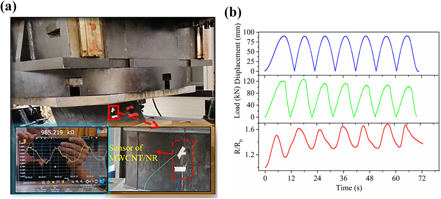
(a) Diagram of pressure shear experimental apparatus and real-time acquisition curve and (b) the resistance response of the MWCNT/NR sensor for monitoring isolation bearing. MWCNT: multiwalled carbon nanotube; NR: natural rubber.
It can be seen from Figure 14(b) that the values of
Conclusions and outlooks
The large deformable resistance-strain sensing MWCNT/NR composite with high sensitivity and stability was prepared by a solution method. The mechanical, conductive, and resistance-strain sensing behavior were investigated systematically. Some key conclusions and outlooks for the future work are listed as follows:
The MWCNTs are dispersed homogeneously in the NR matrix and the relatively low percolation threshold with ∼3.5 wt% has been obtained.
The tensile strength of the MWCNT/NR composites is lower than neat NR (7.54 MPa) when the content exceeds the percolation threshold, such as 5.86 MPa for the 6 wt% MWCNT/NR composite, which is decreased by 22.3%. The modulus at strain 100% of the nanocomposite with 6 wt% MWCNT has been significantly improved to 1.57 MPa, which is increased by 149.2%, compared with the neat NR.
The MWCNT/NR composites exhibited excellent electrical sensitivity (GF > 27) and large strain range (strain > 200%). Meanwhile, the resistance-strain response behavior under different strain amplitudes is studied, and the good repeatability and stability of the MWCNT/NR composites have been found during the stretch–release cycle, especially 8 wt% MWCNT/NR composite, which indicate great potential application in the large deformation monitoring.
The mechanism analysis of ‘shoulder peak’ effect by the DIC method confirms the hysteretic strain for composite hinders the reconstruction of conductive network and induces the ‘shoulder peak’ phenomenon.
Analytical models based on tunneling and hopping effect are developed to investigate resistance-strain sensing behavior of the MWCNT/NR composite. According to the perfect fit between experimental results and analytical models, the contribution by tunneling and hopping effect on the sensing behaviors is confirmed and indicates that the proposed models can predict the resistance–strain relationship well during the stretch process.
According to the experiment results of deformation monitoring to rubber isolation bearings under periodic shear load, the electrical signal output by the composite sensor is stable and synchronous with the shear strain of the rubber isolation bearing, indicating that the MWCNT/NR composite can be used as real-time deformation monitoring for bearing under large deformation.
The fundamental research of MWCNT/NR composites has been achieved in the article and indicates great potential for the application of MWCNT/NR composites in structural deformation monitoring. However, some important environmental factors need to be further studied to promote the application of MWCNT/NR sensor, such as environmental temperature and material aging. The analytical relationship between cyclic strain and electrical signals also needs to confirm. Therefore, there are still some defects and problems to be resolved before the practical application.
Supplementary material
Supplemental Material, sj-pdf-1-nax-10.1177_18479804211011384 - Resistance-strain sensitive rubber composites filled by multiwalled carbon nanotubes for structuraldeformation monitoring
Supplemental Material, sj-pdf-1-nax-10.1177_18479804211011384 for Resistance-strain sensitive rubber composites filled by multiwalled carbon nanotubes for structuraldeformation monitoring by Xingyao Liu, Rongxin Guo, Zhiwei Lin, Yang Yang, Haiting Xia and Zheng Yao in Nanomaterials and Nanotechnology
Footnotes
Author contributions
Conceptualization, RG, YY, and XL; methodology, XL and ZY; validation, RG, YY, and ZL; formal analysis, RG; investigation, XL; resources, RG; data curation, YY; writing—original draft preparation, XL; writing—review and editing, HX; visualization, YY; supervision, RG; and project administration, XL. All authors have read and agreed to the published version of the manuscript.
Declaration of conflicting interests
The author(s) declared no potential conflicts of interest with respect to the research, authorship, and/or publication of this article.
Funding
The author(s) received financial support for the research, authorship, and/or publication of this article: This work was supported by National Natural Science Foundation of China (NSFC) [Grant No.11962009] and Research Center for Analysis and Measurement Kunming University of Science and Technology [Grant No. 2019P20181110006].
Supplementary material
Supplementary material for this article is available online.
References
Supplementary Material
Please find the following supplemental material available below.
For Open Access articles published under a Creative Commons License, all supplemental material carries the same license as the article it is associated with.
For non-Open Access articles published, all supplemental material carries a non-exclusive license, and permission requests for re-use of supplemental material or any part of supplemental material shall be sent directly to the copyright owner as specified in the copyright notice associated with the article.