
Abstract
Despite manufacturers’ goal of molding single component products from plastics, the structures of some of the products are far too complex to be molded as a single piece. Therefore, assembly of subcomponents into the final products is important for the manufacturing of many plastic-based products. To date, welding is the most efficient joining method for plastics. In this study, multiwalled carbon nanotubes were proposed as the susceptor for the microwave welding of high-density polyethylene considering multiwalled carbon nanotube is a good microwave absorber. multiwalled carbon nanotubes were first dispersed in ethanol in an ultrasonic bath to obtain a homogeneous dispersion. Multiwalled carbon nanotubes dispersion was dropped on the targeted area of the prepared dumbbell-shaped sample and dried in an oven at 45°C for 30 min. The sample was then subjected to 800 W microwave irradiation in the domestic microwave oven. The strength of the weld was tested by using tensile testing. Besides, the cross section of the welded joint was characterized by using scanning electron microscopy. The effect of microwave heating duration and the multiwalled carbon nanotube concentration in the dispersion were studied. It was found that the joint strength increased as the heating duration increase from 2 s to 8 s but decreased when the heating duration was further extended to 10 s. Scanning electron microscopic images showed that voids were formed at the joint interface when 10 s was used and resulted in the lowering of joint strength. In the study of the effect of the multiwalled carbon nanotube concentration in the dispersion, joint strength increased when the multiwalled carbon nanotubes concentration increased from 0.25 wt% to 0.75 wt%. However, the joint strength of sample with 1.00 wt% multiwalled carbon nanotube concentration decreased. The presence of a thick unwelded multiwalled carbon nanotubes layer at the joint interface for sample with 1.00 wt% multiwalled carbon nanotubes concentration as shown in scanning electron microscopic image was believed to cause the lowering of joint strength.
Introduction
With its ability to take a good finishing, excellent strength to weight ratio, and good corrosion resistance, thermoplastics such as high-density polyethylene (HDPE) are widely used in many dental implants, orthopedic implants, and medical devices. However, despite manufacturers’ goal of molding single component products from plastics, the structures of most medical devices and implants are far too complex to be molded as a single piece. Therefore, assembling of subcomponents into the final product is important for the manufacturing of many products.
The assembling of plastic components into final products relies on the plastic joining techniques which can be divided into three categories, namely mechanical joining, adhesive bonding, and welding.
For mechanical joining, fasteners such as screws, bolts, and nuts are used. Mechanical joining is easy to manipulate. However, stress concentration easily appears at the bonding region which decreases joint reliability and joining parts result in the increase of weight, thus deteriorate the design of lightweight. 1
Adhesive bonding involves the use of adhesive between components, in which the adhesive transmits load through the joint. Adhesive bonding is relatively mature. However, adhesive bonding needs long process cycle and properties of adhesive joint such as impact resistance, fatigue resistance, and humidity resistance are insufficient. 1 Besides, the mechanical properties of adhesively bonded joint strongly depend on environmental factors. For example, the tensile properties of adhesively bonded glass fiber-reinforced epoxy under hot-wet environment were investigated by Mariam et al. and they reported that the adhesively bonded joint strength and joint elastic modulus decreases as the hydrothermal aging time increases. 2
To date, welding is the most efficient joining method for plastics. Welding involves the melting of plastics at the joint interface followed by the intermolecular diffusion and chain entanglements for the formation of joints. 3 It is, however, not all polymers can be welded, which mainly depends on the classes of polymers. Polymers can be divided into thermosets and thermoplastics. For thermosets, irreversible cross-linking reaction occurs during the processing and curing, and, therefore, thermosets cannot be reshaped by applying heat. For this reason, joining of thermosets can only be obtained by mechanical joining and adhesive bonding. However, thermoplastics are well known for their weldability because they are able to be softened, melted, and remolded by reheating, and, therefore, thermoplastic can be welded upon application of heat and pressure. 4
Welding process can be categorized based on heating method, namely external heating and internal heating. External heating methods such as hot tool, hot gas, and extrusion rely on convection and/or conduction to heat the weld surface. Hot tool welding requires complex tools that allow the hot surface to match the contours of the joint interface. 5 For hot gas and extrusion welding techniques, a v-groove is required for proper joint formation at a very slow rate, and the properties are highly dependent on the operator’s skill level. 6 For internal heating, heat is generated by conversion of mechanical energy through surface friction (internal mechanical heating) or intermolecular vibration (internal electromagnetic heating). Welding by internal mechanical heating such as ultrasonic welding mainly performs spot welding. Machines as well as tools are expensive and part preparation is time-consuming. 1 Although friction stir welding has the advantage of short processing time and does not require consumables, this method causes root effect and thickness reduction at the weld line which may reduce the welding strength. 7 Welding by internal electromagnetic heating is a relatively new method that relies on the absorption and conversion of electromagnetic such as microwave and laser into heat. Laser welding has been used for the welding of thermoplastic dental implants, orthopedic implants, and medical devices because it is a clean, precise, and near error-free joining process. However, laser welding requires extremely expensive equipment and high capital investment which incurs high cost to the final products.
Microwave is the electromagnetic radiation with frequency ranges from 300 MHz to 300 GHz and wavelength ranges from 1 mm to 1 m. For microwave welding, a layer of electromagnetic absorbent material, known as the susceptor, is placed between the parts to be joined. 8 The susceptor is heated by absorbing microwave energy which subsequently heats and melts the surrounding polymer via conduction. 9 Materials containing polar groups in their molecular structure are able to absorb microwave energy with the most common implant material being polyaniline (PANI). Some thermoplastics such as acrylonitrile butadiene styrene, polyvinyl chloride, and nylon contain polar groups in their molecular structure and are able to be welded without an additional absorbing layer. Limited studies have been performed on microwave welding of thermoplastics since it is a relatively new polymer welding technique. Wu and Benatar developed a microwave joining method (butt joint) for HDPE using PANI at the weld line. 10 They found that the thickness of the molten layer influenced strength. Greater thickness results in stronger bonds. At the optimal welding conditions, the tensile strength of the weld was equal to that of the HDPE bulk strength (25 MPa). Staicovici et al. studied the welding and disassembling of HDPE butt joints with various PANI concentrations at the weld line. 11 They found that the tensile strength of the joints could reach that of the bulk material strength of HDPE under the right conditions. However, the PANI concentration that resulted in effective disassembly displayed a maximum joint strength of only 80% of the bulk material, that is, PANI concentrations that achieved joint strengths equal to the bulk material did not disassemble effectively. 8
Other than polar materials, many attempts have been made for the welding of thermoplastic using carbon-based materials such as graphite and carbon nanotubes (CNTs). Carbon materials show high microwave absorbing properties due to their excellent relative permittivity and conductivity. 12 Lately, Sun et al. successfully welded polypropylene (PP) using graphite powder as susceptor. 13 They reported that the joint strength of the welded joint is higher when graphite powder after subjecting to ball-milling was used (90 μm) compared with those without subjecting to ball-milling (250–850 μm). They claimed that graphite powder with smaller size can effectively absorb microwave energy due to their high surface-to-volume ratio.
CNTs are tubular allotropes of carbon in nanoscale that has a high length to diameter ratio. CNTs consist of single or multiple concentric rolled graphene layers, in single-walled CNTs and multiwalled CNTs (MWCNTs), respectively. CNTs have excellent mechanical properties, high aspect ratios, and large interfacial area that render them promising reinforcements for the enhancement of mechanical properties of polymer matrix composites. For example, Kalakonda et al. prepared MWCNTs/polyurethane nanocomposites by backfilling preformed hydrogels and aerogels of individually dispersed MWCNTs (MWCNTs-Baytubes) and thermoplastic polyurethane. 14 In their study, they first prepared a porous network form by solution fabrication method with MWCNTs in hydrogel- and aerogel-forms concentration to prevent agglomeration, followed by soaking the porous network in a polymer solution of concentration 1–6 wt% for 5–10 h at 50°C to facilitate polymer infiltration into the nanotube network. Finally, they evaporated the solvent, annealed the composites under vacuum at 150°C for 12 h, and removed all voids by hot-pressing method at 130°C for 10–15 min. They observed an improvement in tensile modulus about 200-fold over that of pristine polymer when 19 wt% MWCNT loading was used which indicates MWCNTs can be used to improve mechanical properties of polymer matrix composites. However, their process involved several steps and required at least 17 h of preparation for the nanocomposites. Recently, CNTs/polylactic acid (PLA) composite coating was employed for the welding of thermoplastics. The presence of delocalized sp2 π electron in CNTs makes them a good microwave absorber. 15 Sweeney et al. reported that the welding of 3D-printed thermoplastic is using intense localized heating of CNTs/PLA coating by microwave irradiation for 60 s. 16 The weld fracture strength was reported to improve by 275%. In another study, Sun et al. reported the microwave welding of PP using pre-prepared CNTs-PLA solder system. 17 They demonstrated that the welded PP joint shows high bonding strength due to the formation of CNT-filled PP nanocomposite at the joint. These studies indicated that microwave welding using CNTs-filled composites coating as susceptor can provide a fast joining of thermoplastic with excellent strength of the welded joint. However, additional steps were required for the preparation of CNTs-filled composite coating or CNTs/PLA solder system before they can be used as microwave susceptors. Besides, microwave susceptors such as CNTs-filled composite coating in the form of bulk solid cannot be used for the welding of structure with complex geometrical configuration.
To date, no study was reported on the use of only CNTs as the susceptor for microwave welding of thermoplastic. By using CNTs alone as susceptors, no preparation of CNTs filler composite coating is required and the microwave welding process is, therefore, less time-consuming. The microwave welding process of thermoplastic can be achieved within 1 min. Besides, CNTs can also be applied easily as susceptors on structure with complex geometrical configuration. This microwave welding method can widen the application of MWCNTs-polymer composite for advanced applications such as smart coating materials for deicing by self-heating as well as by detection of the freezing temperature as reported by Jang et al. 18 In this article, MWCNTs were used as susceptor for the microwave welding of HDPE. Previous study shows that the thickness of the molten layer influenced strength, whereby greater thickness results in stronger bonds. The amount of susceptor and the microwave heating duration can significantly affect the thickness of the molten layer at the joint. Therefore, in this study, the effect of concentration of MWCNTs in dispersion and microwave heating duration on the tensile strength and microstructure of cross section of the welded joint were also studied and reported.
Materials and methods
Materials
HDPE pellets (Lotte Chemical Titan (M) Sdn Bhd, Malaysia), MWCNTs (Fibermax Composites, Greece), and ethanol (Bendosen, Malaysia) were used as received without further purification.
Methodology
HDPE pellets were used to produce dumbbell-shaped sample by using a hot press machine (GoTech, Taiwan) and ASTM D638 Type IV dumbbell cutter (in-house made). After that, the samples were cut into the shape as shown in Figure 1. MWCNTs were mixed with ethanol and distilled water (weight ratio 1:1) in four mass fractions, which are 0.25, 0.50, 0.75, and 1.00 wt% by using an ultrasonic mixing bath for 1 h.

Sectioned dumbbell-shaped sample.
A targeted area of 1 cm2 was marked on the HDPE dumbbell-shaped sample. About 0.15 ml of MWCNTs containing dispersion was dropped on the targeted area and dried in an oven at 45°C for 30 min. Another sample was placed on top of the sample with MWCNTs coating as shown in Figure 2 and the sample was subjected to microwave heating.

Schematic diagram of HDPE dumbbell-shaped sample with MWCNTs coating between their targeted area. HDPE: high-density polyethylene; MWCNT: multiwalled carbon nanotube.
The sample was placed in an 800 W domestic microwave oven (Panasonic NN-S215MF, 2.45 GHz, Panasonic, Malaysia) for microwave heating. For the study of effect of heating duration, dispersion with 0.50 wt% concentration of MWCNTs and microwave heating time of 2, 4, 6, 8, and 10 s were used. For the study of effect of concentration of MWCNTs in dispersion, microwave heating duration of 8 s was used and the concentration of MWCNTs in dispersion varied from 0.25 wt % to 1.00 wt%. A glass slide was used to exert pressure on the sample and cutoff parts were used to balance the sample as shown in Figure 3.

Schematic diagram of setup for microwave heating in a microwave oven.
Characterizations
The cross section of the samples was examined by using scanning electron microscopy (SEM, JEOL JSM-6460LA, JEOL Ltd, Japan). To obtain the cross section sample of the welded joint, cryofracture method was used. The sample was put into 500 ml of liquid nitrogen for 1000 s. Cutting at the welded joint was done immediately after the sample was removed from liquid nitrogen. The sample was coated with platinum by using sputter coater before subjecting to examination using SEM.
Mechanical properties of samples were studied by using a universal testing machine (UTM, Instron 5569, Instron, Malaysia). The crosshead speed was set to 50 mm/min. The cutoff parts of dumbbell shape was attached to the samples by using epoxy glue so that the sample was balanced and straight when it was gripped on the UTM machine. The sample was pulled until fracture. The setup of sample in UTM was shown in Figure 4.

Schematic diagram of gripping of sample in UTM machine. UTM: universal testing machine.
Results and discussion
Effect of microwave heating duration
Figure 5 shows the comparison of tensile strength of the samples that were subjected to different microwave heating duration. Figure 5 shows that the tensile strength increases with the increasing heating duration from 2 s to 8 s. The tensile strength of samples subjected to 2 and 4 s is lower than the tensile strength of the pure HDPE. The maximum tensile strength of 7.5 MPa was observed when 8 s was used. The tensile strength decreases when 10 s was used. It is believed that as the heating duration was increased from 2 s to 8 s, MWCNTs absorbed sufficient energy from the microwave and melted the surrounding HDPE, subsequently resulted in the welded joint with improved joint strength. However, as the heating duration was further increased to 10 s, defects such as void may form at the joint due to prolonged microwave heating and resulted in lower joint strength. Wu et al. reported a similar result in their study of using MWCNT/PP composite for the welding of PP substrate. 19 They reported that the strength increased when the heating duration was increased from 30 s to 50 s. Wang et al. also reported that the peeling strength of the polycarbonate (PC)/MWCNT increased due to intercalation of MWCNTs by microwave heating into PC surface when the heating duration was increased from 5 s to 10 s. 20 It is worth mentioning that the tensile strength of samples subjected to 6 and 8 s is slightly higher than the tensile strength of the pure HDPE. Generally, it is known that CNTs have a higher tensile strength than HDPE. In this study, the addition of CNTs as susceptors led to the formation of CNTs-filled HDPE nanocomposite at the welded joint, which has enhanced mechanical properties than the pure HDPE. Therefore, samples subjected to 6 and 8 s have higher tensile strength than pure HDPE. Similar results were reported by Sweeney et al. 16 In their study, the fracture strength of microwave-welded 3D-printed PLA coupons using CNTs/PLA composite coating as susceptors increased significantly, compared with the bulk PLA and 3D-printed PLA control, which was due to the formation of nanocomposite at the welded joint.
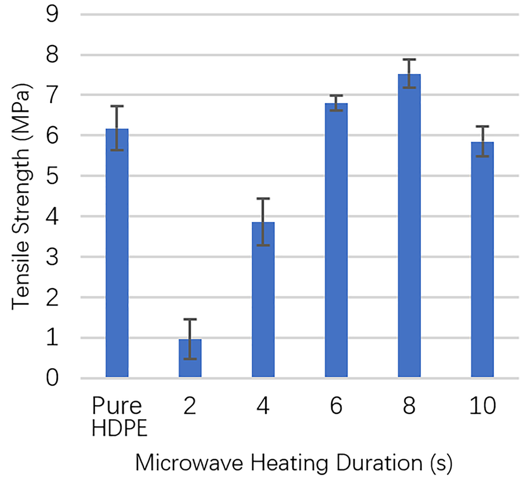
Tensile strength of samples subjected to different microwave heating duration.
Figure 6 shows the photographs of tensile test samples subjected to different microwave heating duration. Figure 6(a) shows that sample subjected to 2 s heating duration detached during the tensile test. It indicates that the welded joint is not strong to hold the welded dumbbell-shaped sample together when tensile test was conducted, resulting in a very low tensile strength. Figure 6(b) shows that tensile test sample subjected to 8 s heating duration and 8 s sample experienced necking before failing. The failure of 8 s sample occurred at the position right next to the welded joint as shown in Figure 6(b). Figure 6(c) shows that tensile test sample subjected to 10 s heating duration. The 10 s sample failed at the welded joint. Naked eye examination of the sample shows the presence of voids in the welded joint.

Photograph of tensile test sample of HDPE subjected to heating duration of (a) 2 s, (b) 8 s, and (c) 10 s. HDPE: high-density polyethylene.
SEM images were obtained for sample that was subjected to microwave heating of 8 and 10 s. Figure 7 shows the SEM images of cross section of welded joint for sample that was subjected to microwave heating of 8 s. Figure 7(a) shows the presence of welded joint. Figure 7(b) shows the magnified image of the welded joint area in the yellow circle as in Figure 7(a). Figure 7(b) shows the formation of MWCNTs-filled HDPE composite at the welded joint. The formation of MWCNTs-filled HDPE composite at the welded joint is due to the good microwave absorbing properties of MWCNTs. When the sample was subjected to microwave heating, MWCNTs absorbed the microwave energy and were heated up. The heat from MWCNTs melted the surrounding HDPE and the MWCNTs protruded into the melted HDPE. When the microwave oven was turning off, molten MWCNTs-containing HDPE solidified to form MWCNTs-filled HDPE composite at the welded joint.

SEM image of cross section of welded joint for sample that was subjected to microwave heating of 8 s: (a) ×50 and (b) ×20,000. SEM: scanning electron microscopic.
Figure 8 shows the SEM image of cross section of welded joint for sample that was subjected to microwave heating of 10 s. Void was observed at the welded joint when 10 s was used, which may be due to the prolonged microwave heating, which led to the thermal degradation of HDPE. Thermal degradation of the HDPE may form volatiles or other decomposition byproducts that caused voids at the weld interface. The presence of void has led to the reduction of tensile strength for 10 s sample as shown in Figure 5 due to the poor weld quality. The presence of voids in the welded joint is in good consistency with the photograph of tensile test sample subjected to heating duration of 10 s in Figure 6(c).

SEM image of cross section of welded joint for sample that was subjected to microwave heating of 10 s. SEM: scanning electron microscopic.
Effect of concentration of MWCNTS in dispersion
Figure 9 shows the comparison of tensile strength of the samples that were prepared by using dispersion with different concentrations of MWCNTs. It can be observed that the tensile strength of the samples increased when concentration of MWCNTs in dispersion was increased from 0.25 wt% to 0.75 wt%, with the highest tensile strength of 8 MPa when dispersion with 0.75 wt% MWCNTs was used. However, there is a drop of tensile strength when concentration of MWCNTs in dispersion was further increased to 1.00 wt% sample. It is believed that when concentration of MWCNTs in dispersion was increased from 0.25 wt% to 0.75 wt%, the higher filler loading in the welded joint led to higher joint strength. However, as the concentration of MWCNTs in dispersion was further increased to 1.00 wt%, the amount of MWCNTs might be too high and led to the formation of inhomogeneous-welded joint or welded joint with defects, which caused stress concentration.
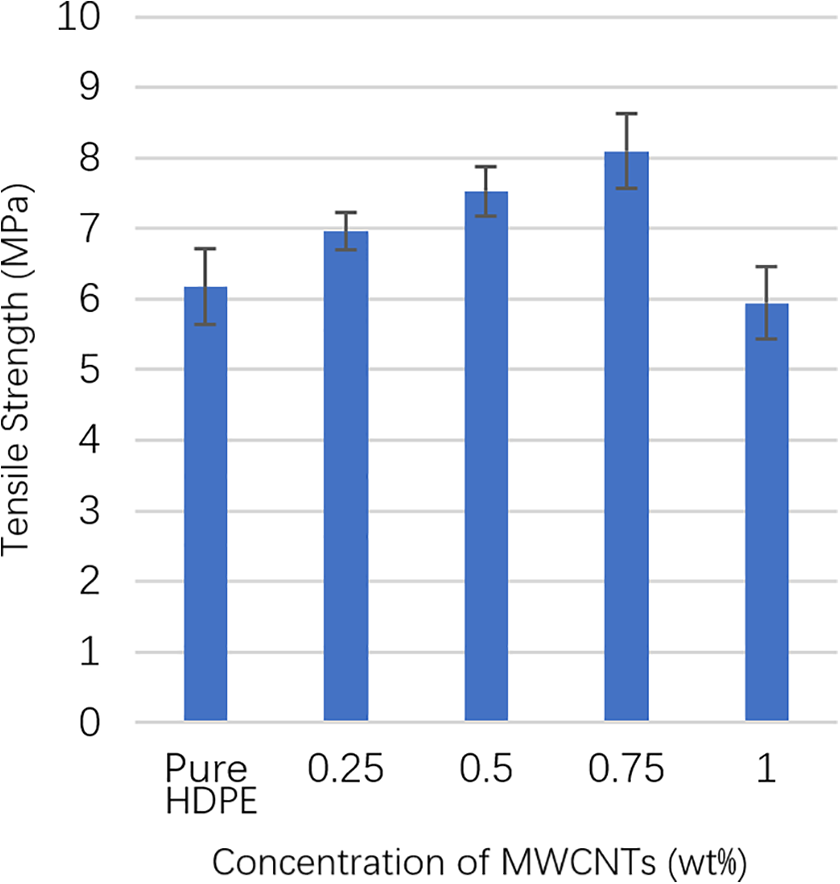
Tensile strength of samples prepared using dispersion with different concentrations of MWCNTs. MWCNT: multiwalled carbon nanotube.
Comparison between SEM images for sample prepared using dispersion with 0.50 and 0.75 wt% MWCNTs was shown in Figure 10. Both images show the presence of protrusion of MWCNTs from the HDPE surface, indicating the formation of MWCNTs-filled HDPE composite at the welded joint. It is also observed that sample prepared using dispersion with 0.75 wt% in Figure 10(b) shows significantly more MWCNTs protrusions compared with the 0.50 wt% sample. The formation of MWCNTs-filled HDPE composite with higher filler loading at the welded joint is believed to result in higher tensile strength for 0.75 wt% sample.

SEM image of cross section of welded joint for sample that was prepared using dispersion with concentration of MWCNTs: (a) 0.50 wt% and (b) 0.75 wt%. SEM: scanning electron microscopic; MWCNT: multiwalled carbon nanotube.
Figure 11 shows the SEM images of cross section of welded joint for sample that was prepared using dispersion with 1.0 wt% concentration of MWCNTs. It can be observed from Figure 11(a) that there is a void between the MWCNTs-filled composite at the welded joint. Figure 11(b) shows the magnified image of the area denoted by the yellow circle in Figure 11(a). It clearly shows that the surface is packed with free-standing MWCNTs, which penetrated into only one side of the HDPE plate. This indicated the amount of MWCNTs at the welded joint is too high that a thick layer of MWCNTs, which penetrated to only one side of the HDPE plate, was formed. This MWCNTs-filled composite layer cannot effectively join the two HDPE interfaces and resulted in weak-welded joint with lowered tensile strength.
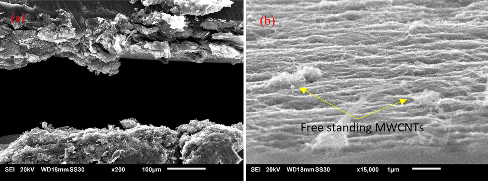
SEM image of cross section of welded joint for sample that was prepared using dispersion with 1.0 wt% concentration of MWCNTs: (a) ×200 and (b) ×15,000. SEM: scanning electron microscopic; MWCNT: multiwalled carbon nanotube.
Conclusions
In conclusion, MWCNTs can be used as the susceptor for the microwave welding of HDPE. In the study of effect of microwave heating duration, dispersion of MWCNTs with 0.50 wt% concentration was used and the heating duration was varied from 2 s to 10 s. The tensile strength of the welded samples increased as the heating duration increased from 2 s to 8 s and decreased when heating duration was further increased to 10 s. The reduction of tensile strength is due to the formation of void at the welded joint when 10 s was used. In the study of effect of concentration of MWCNTs in dispersion, microwave heating duration of 8 s was used and the concentration of MWCNTs in dispersion varied from 0.25 wt% to 1.00 wt%. It was found that the tensile strength of the welded samples increased as the concentration of MWCNTs increased from 0.25 wt% to 0.75 wt% and decreased when the concentration was further increased to 1.00 wt%. The lowering of the tensile strength of the sample prepared with dispersion of 1.00 wt% MWCNTs is due to the penetration of MWCNTs into only one side of the HDPE plate which cannot effectively join the two HDPE interface and resulted in weak-welded joint.
Footnotes
Declaration of conflicting interests
The author(s) declared no potential conflicts of interest with respect to the research, authorship, and/or publication of this article.
Funding
The author(s) disclosed receipt of the following financial support for the research, authorship, and/or publication of this article: This work was supported by the Department of Education, Ministry of Education Malaysia (MOE) through Fundamental Research Grant Scheme (FRGS/1/2019/TK05/UNIMAP/02/7) [FRGS 9003-00729].