
Abstract
Dissimilar weld between a mild steel and a stainless steel-316 was formed by exposing the candidate materials to electromagnetic radiation in the microwave band. Characterisations of the joints were carried out with respect to some aspects of microstructural and mechanical properties of the fusion joints. The joining trials were carried out in an industrial microwave applicator at a fixed frequency of 2.45 GHz and 1.2 kW power while exposed for a duration of 600 s in atmospheric condition. Stainless steel-316 powder was used as the filler material for joining. Principles of microwave hybrid heating were utilised for heating and subsequently melting the metal-based materials in the joint zone. Characterisation of the microwave hybrid heating–induced dissimilar welds were carried out using X-ray diffraction, field emission scanning electron microscopy, microhardness tester and universal testing machine. The presence of carbides and intermetallic in the joint zone were evidenced in the X-ray diffraction results. The microstructures observed through scanning electron microscope show the metallurgical bonding between the substrates to be joined through complete melting of the powder particles and fusion of the base materials. The Vicker’s microhardness in the core of the joint was observed to be 380 HV, which was significantly higher as compared to the base materials due to the formation of dendritic structure and various carbides in the joint zone during microwave hybrid heating process. The average ultimate tensile strength of the joints was measured to be 420 MPa with an elongation of 6.67%. The average flexural strength of the joints was observed to be 787.5 MPa with an elongation of 5.14%. The optimum temperature required for joining was measured using an in-built non-contact infrared pyrometer and was found to be 1360 °C.
Introduction
Joining of materials is one of the most important requirements in manufacturing and assembly operation. Joining, be it permanent or temporary, often becomes the finishing technical task before a product being shipped. Efficiency in joining process and the joint quality could influence the economics of production significantly. Importantly, techniques of joining and the operating parameters vary to a large extent with different materials to be joined and the required joint quality. Stainless steel (SS-316) and mild steel (MS) are two of the most widely used materials in a number of applications. Their dissimilar welds are widely used in pressure vessels, boilers, construction of vessel, heat exchangers of power generation industry and petrochemical plants. 1 However, there are a number of problems in welding of dissimilar welds such as solidification cracking, hydrogen cracking and the formation of brittle intermetallic products, which lead to failure of weld before the expected design life. 2 Also, the selection of filler material in the dissimilar material joining is very critical. The filler material must have a good metallurgical compatibility with the substrates to be joined. Considering the wide applications of dissimilar joints, the objective of this work is to investigate the feasibility of dissimilar welds between SS-316 and MS using microwave heating.
Microwave heating of materials is different from conventional heating of materials because the electromagnetic energy is directly delivered to the materials through molecular interaction and there is energy conversion rather than energy transfer which generally occurs in conventional processing of materials. Microwave heating of materials is gaining popularity because of its volumetric heating characteristics which reduces the possibility of cracks, residual stresses and thermal distortion at the target materials.3–6 Earlier, the microwave heating of materials was used in processing of ceramics, ceramic composites, polymers and semi-conductors in the form of synthesising, sintering and joining applications, because these materials are good absorbers of microwave at room temperature.7–10 However, processing of bulk metallic materials using microwave energy is a challenging issue because these materials do not allow microwave to penetrate inside due to the presence of electron cloud. However, bulk metallic materials start absorbing microwaves at high temperature because of their increased dielectric loss. This creates an opportunity for processing of bulk metallic materials using microwave hybrid heating (MHH) technique.
Microwave melting of bulk metals such as aluminium, copper and stainless steel was reported by Agrawal 11 in the year 2006. Chandrasekaran et al. 12 reported microwave melting of lead, tin, aluminium and copper. The authors had reported that the microwave melting of materials was twice as fast and more energy efficient compared to conventional melting of materials. Processing of bulk metallic materials in the form of joining was reported by Sharma et al. 13 in the form of a patent. Srinath et al.14–16 reported joining of similar (SS-316 to SS-316, copper to copper) as well as dissimilar materials (SS-316 to MS) using MHH. The authors have reported joining of SS-316 and MS using Ni powder as an interface layer with the help of MHH. However, the interfacing material plays an important role in joining of dissimilar materials. The properties of the efficient joints between two dissimilar materials largely depend on the interfacing (filler) material. The filler materials used must have good solubility between the base materials to be joined.
In this article, dissimilar weld between SS-316 and MS base materials has been carried out using SS-316 powder as a filler material through the principles of MHH. The temperature on the upper surface of the susceptor was monitored using a non-contact infrared pyrometer with quartz window. The relationship of microstructure, microhardness, flexural strength and tensile properties of the joints is discussed in the article.
Experimental procedure
The following sections explain the experimental procedure adopted for development of dissimilar weld using MHH. Different characterisation techniques employed for evaluating the joint properties have also been briefly elucidated.
Material selection
The dissimilar welds of SS-316 and MS are widely used in construction vessels and heat exchangers for several industrial applications. Therefore, SS-316 and MS were chosen as candidate materials for dissimilar weld using MHH. The SS-316 powder with an average particle size of about 50 µm was used as a filler material. A typical morphology of the powder used in the present trials is shown in Figure 1. The powder particles are, in general, elliptical in shape with relatively rough exterior. The rough external surface provides higher surface area which is advantageous for heat transfer. The chemical composition of the base metal of dimension 25 mm × 10 mm × 4 mm and filler material is given in Table 1. The compositions of the bulk SS-316 plates and the interfacing powder are nearly same. However, there is marginal higher content of Si in the interfacing powder.
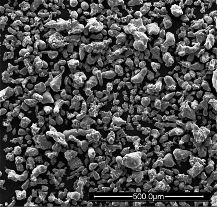
A typical SEM micrograph illustrating the morphology of the SS-316 powder used as the filler (interfacing) material.
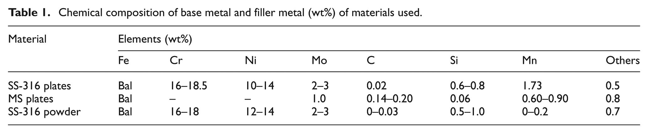
Chemical composition of base metal and filler metal (wt%) of materials used.
Fabrication of dissimilar joints
The interfacing surfaces of base materials were cleaned with acetone prior to joining. The powder was preheated in a muffle furnace at 200 °C for 2 h to remove moisture. The powder was mixed with chemically neutral epoxy resin (Bisphenol-A, Blummer 1450XX) to make slurry. The prepared slurry was easily filled between the interfacing surfaces to be joined. The whole assembly was placed over an alumina plate. The alumina plate was kept inside the hot zone of a refractory box. The alumina plate acts as a separator between the refractory box and the metallic pieces to be joined. The alumina plate was used because it has high melting point. The refractory box was made from a material having low dielectric loss; hence, microwave can pass through it without any interruption. The refractory box also acts as a thermal insulator to the heat developed in the hot zone of refractory box during the experiment. Following this, the fixture was placed in an industrial microwave oven (make: Enerzi Microwave Systems Pvt Ltd). The exposures were carried out at a fixed frequency of 2.45 GHz and a power of 1.2 kW. Bulk metallic materials reflect microwave at room temperature, and hence they were covered with insulating materials to avoid any direct coupling with microwave radiation. The resin in the slurry is a good absorber of microwave radiation; hence, it couples with microwave radiation at room temperature and gets evaporated at a temperature approximately 400 °C. Thus, the epoxy has no effect on the joint properties to be formed. The powder particles fail to couple with microwave radiation initially due to their low skin depth. The skin depth of materials can be calculated using the following relationship

where δ is the skin depth in µm, ρ is the resistivity in µΩ-m, f is the frequency of microwaves (2.45 GHz in this study),
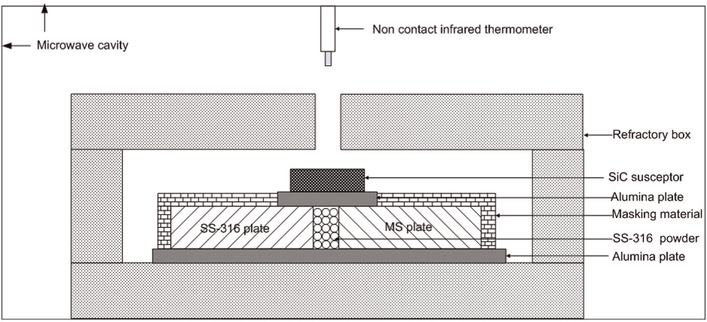
Schematic of joining bulk metal-based materials using MHH.
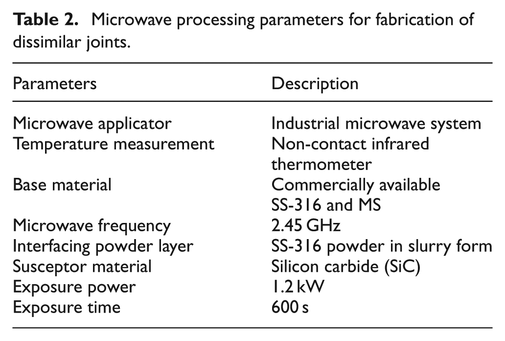
Microwave processing parameters for fabrication of dissimilar joints.
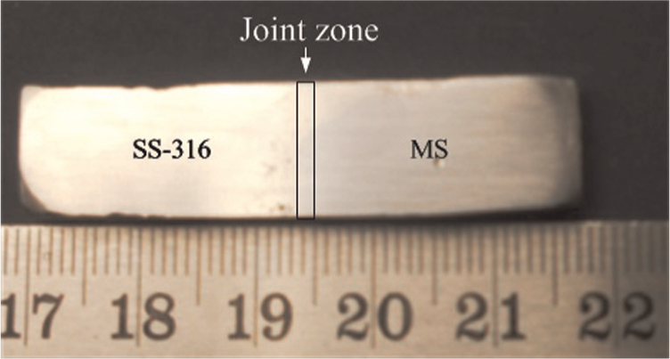
An optical micrograph of the dissimilar weld between the MS and SS-316 obtained through microwave heating.
Characterisation of the joints
The microwave-induced dissimilar joints were cut perpendicular to welding direction using a 200-µm-thick diamond cutter (make: Chennai Metco; model: Baincut LSS), followed by mechanical polishing and etching according to standard metallographic methods. The characterisations of the microwave-induced dissimilar joints were carried out through X-ray diffraction (XRD), optical microscope, field emission scanning electron microscopy (FE-SEM), measurement of microhardness and porosity. The etched samples were observed through optical and FE-SEM equipped with energy-dispersive X-ray detector (make: FEI; model: Quanta 200 FEG) for identifying its microstructure features and to determine the elemental composition at various phases of the joint zone. The XRD analysis was carried out to analyse different phases present in the joint zone. The XRD data were taken at room temperature in a Bruker AXS diffractometer with Cu-Kα X-ray. The scan rate was used from 0.5°/min and scan range was maintained in the range of 10°–100°. The X-ray elemental composition analysis of the fusion zone was carried out inside the grain and on the grain boundary in the joint zone. The microhardness of the joint specimen was measured on the cross section perpendicular to the welding direction and on either side of base metal using a constant load of 25 g and a loading time of 10 s. The joint tensile strength and flexural strength were measured using a computer-controlled universal testing machine (make: Instron; model: 5982) at a crosshead speed of 0.2 mm/min. The specimens were prepared according to the American Society for Testing and Materials (ASTM) standard having a gauge length of (specimen) 18 mm with 3.5 mm width for tensile testing, and for three-point bending strength the specimens have a span length of 35 mm, width 10 mm and 4 mm thickness. Five joint specimens were tested for each tensile as well as three-point bend tests and average values were recorded.
Results and discussion
Dissimilar welds between MS and SS-316 were developed through MHH technique as discussed in the previous section. Characterisation results of the developed joints are discussed with suitable illustrations in the following sections.
XRD observation
The XRD spectra of as-received powder SS-316 and the joint zone are shown in Figure 4. The XRD spectrum of as-received SS-316 powder (Figure 4(a)) is coincident with solid solution face centred cubic (FCC) austenitic matrix. On the other hand, the XRD spectrum of the joint zone (Figure 4(b)) shows the presence of nickel iron oxide (NiFe2O4), iron nickel (FeNi) and chromium carbide (Cr7C3, Cr23C6) corresponding to 2θ value of 35.744°, 62.728° (NiFe2O4), 43.694°, 50.978° (FeNi), 44.370° (Cr7C3) and 82.358° (Cr23C6) along with the main austenite matrix. The formation of NiFe2O4 is attributed to the fact that the experiment was carried out in atmospheric condition. The formation of chromium carbide is due to strong affinity of chromium to react with carbon at high temperature. The presence of various carbides as well as intermetallics in the joint zone further enhances the coupling of microwave to the interfacing layer due to their increased dielectric losses. This will result in rapid rise in the temperature of the joint zone, which causes localised melting and consequently metallurgical bonding with the interfacing surfaces.
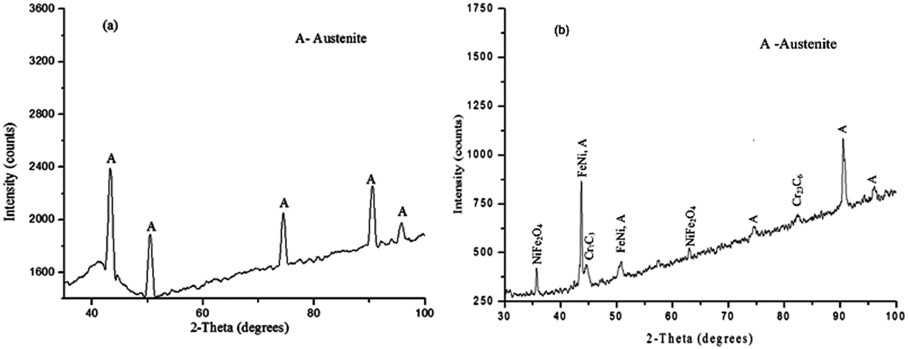
The XRD spectra of (a) as-received SS-316 powder and (b) joint zone developed through MHH.
Joint zone microstructure
A typical back scattered electron (BSE) micrograph of the dissimilar weld developed through MHH is shown in Figure 5(a). The micrograph shows good metallurgical bonding on either side of the base material through complete melting of powder particles. Figure 5(b) shows the joint zone at higher magnification. The optical micrograph (Figure 5(c)) shows the interface between the joint zone and the SS-316 substrate. The optical micrograph (Figure 5(d)) shows the interface between the MS substrate and the joint zone. The interface was perfect with no visible evidence of discontinuity. It was observed that dendrites were formed in the entire joint zone microstructure as shown in Figure 5(b). At the end of the irradiation cycle, the melted layer solidifies from the partially melted grains at the interfacing surfaces. Depending on the solidification condition and factors such as total amount of alloying and impurity systems present, the mode of solidification can be planar, cellular or dendritic. The formation of dendritic structure developed in the fusion zone can be explained on the basis of growth rate (R) and thermal gradient (G). It is well known that solidification front will be dendritic at low (G/R)1/2, columnar dendritic at medium (G/R)1/2 ratio and fully cellular at high (G/R)1/2 values. For joining steels, the value of (G/R)1/2 ratio is generally large near to the fusion line and it results in the formation of dendritic structure in the fusion zone. Thus, a dendrite type of structure is developed, but the formation of secondary arms, a characteristic of the dendritic structure, is suppressed. This is due to the fact that thermal gradient existing in the transverse direction near the fusion line is relatively small compared to the longitudinal growth direction. Thus, the dendritic grains will grow in the direction opposite to heat flow direction.
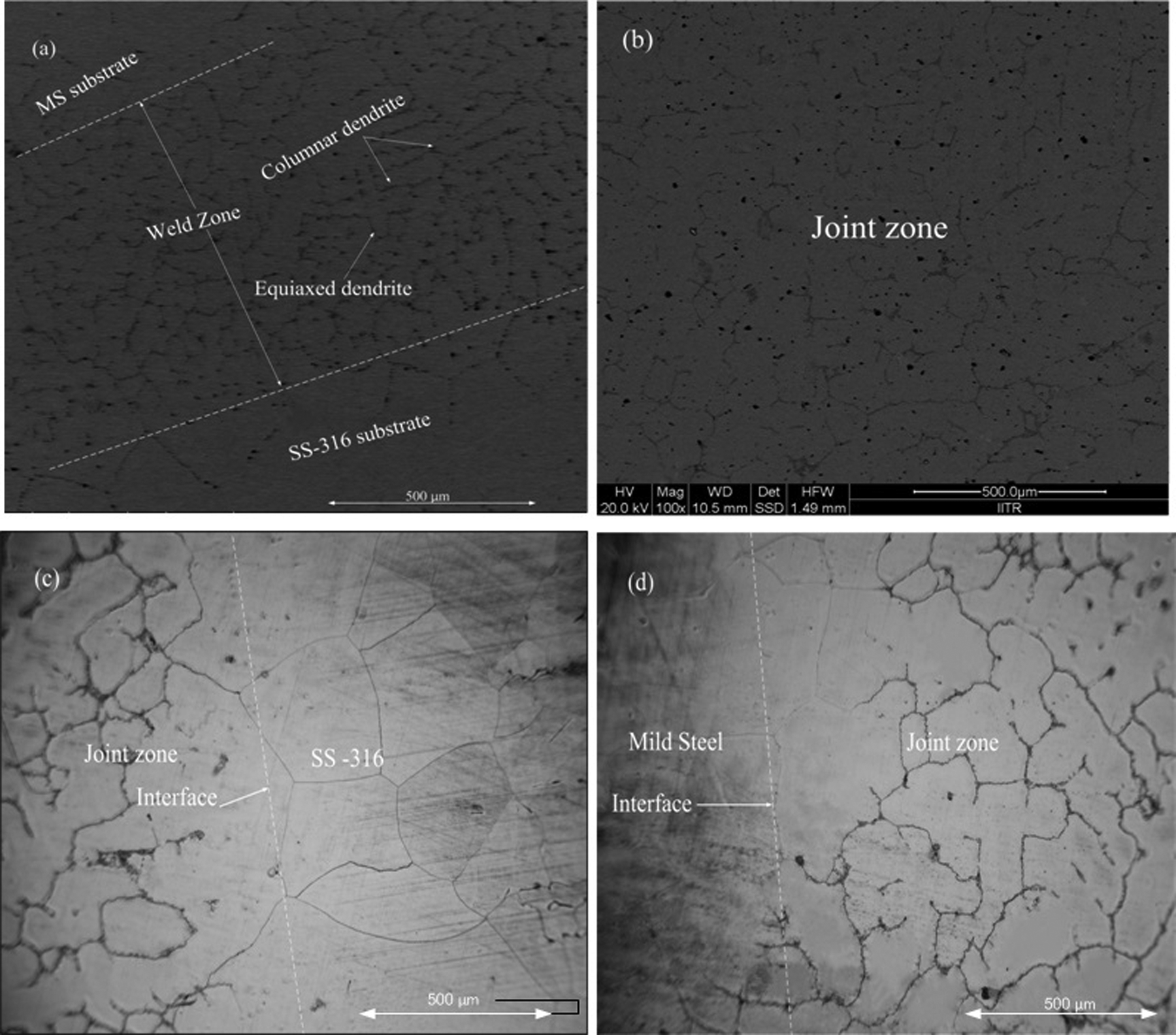
(a) BSE micrograph of dissimilar weld with different zones developed through MHH, (b) BSE micrograph of joint zone at higher magnification, (c) optical micrograph showing interface between the joint zone and SS-316 and (d) optical micrograph showing interface between the joint zone and MS.
Elemental study
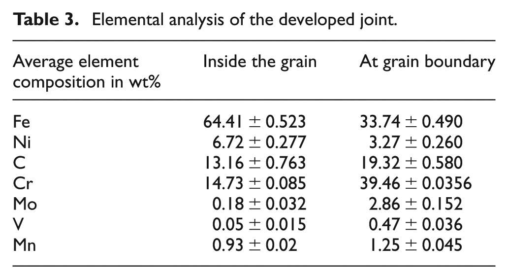
The elemental constituents of the different phases present in the weld zone were ascertained through X-ray elemental composition analysis. The location for determining the elemental constituents was grain interior and the grain boundary of the joint zone as indicated by points 1 and 2 in Figure 6(a), respectively. The corresponding energy-dispersive spectroscopy (EDS) is illustrated in Figure 6(b) and (c). The EDS analysis has been carried out at three different points inside the grains and the grain boundary, and the corresponding average elemental distribution is indicated in Table 3. It is seen from Table 3 that Cr, Mo and V have a higher percentage at grain boundary as compared to inside the grain. These elements have strong tendency to react with carbon at high temperature which triggers the formation of various carbides. The formation of various carbide in the fusion zone was also confirmed by XRD spectrum (Figure 4(b)). Carbides are mostly located at the grain boundaries, because grain boundaries are open in structure and diffusion of elements can easily take place at the grain boundaries.
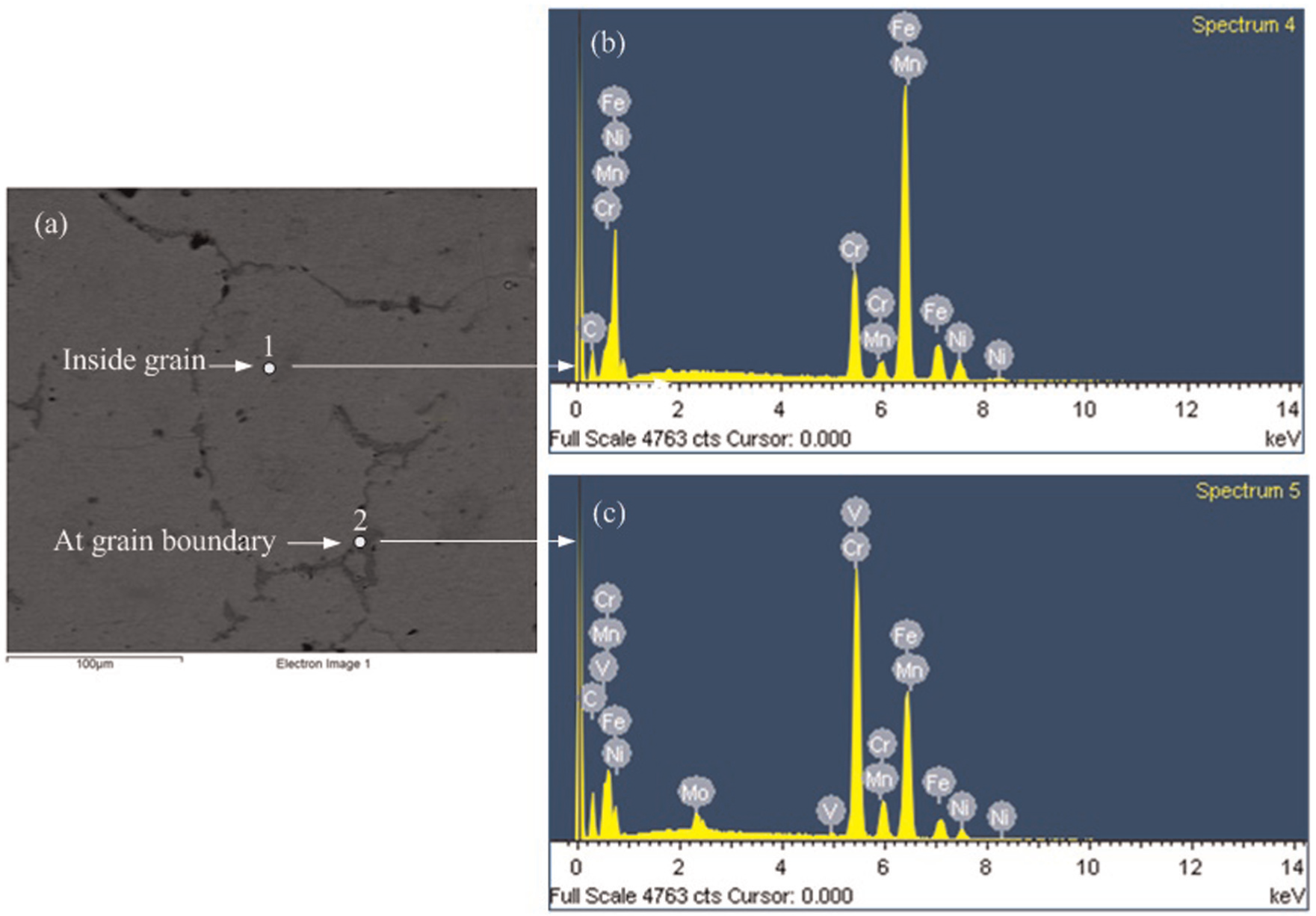
(a) Location for elemental composition analysis. EDS spectra of the welded zone: (b) inside the grain and (c) at grain boundary.
Elemental analysis of the developed joint.
Microhardness study
The microhardness data are related to specific structure developed in the fusion zone. Development of specific structure depends on the alloy addition, prior austenite grain size and cooling rate experienced during solidification. Their combined effects can be studied by considering their hardness. The indentations were made on the joint zone and on both sides of parent materials at a regular interval of 200 µm using a load of 25 g for 10 s. The variations in the microhardness across the joints and on both sides of base metals are shown in Figure 7. The microhardness in the core of the joint zone was significantly higher (approximately 380 HV) as compared to base metal. The presence of relatively fine grain size as compared to base metal results in an increase in hardness of the joint zone and it relates to Hall–Petch relationship; H = Ho + k D1/2, where Ho relates the materials’ hardness of infinite grain size, k is the constant that represents the grain boundary as an obstacle to movement of dislocation and D is the grain diameter. 17 Thus, the fine grain size present in the fusion zone results in higher hardness of the joint. The high hardness in the fusion zone is also attributed to the presence of various carbides as evidenced from the XRD spectrum (Figure 4(b)). The formation of dendritic structure along with rapid cooling rate associated with MHH process leads to extensive segregation in the interdendritic regions. As a result of this, the formation of various carbides, predominantly chromium carbide, will take place.
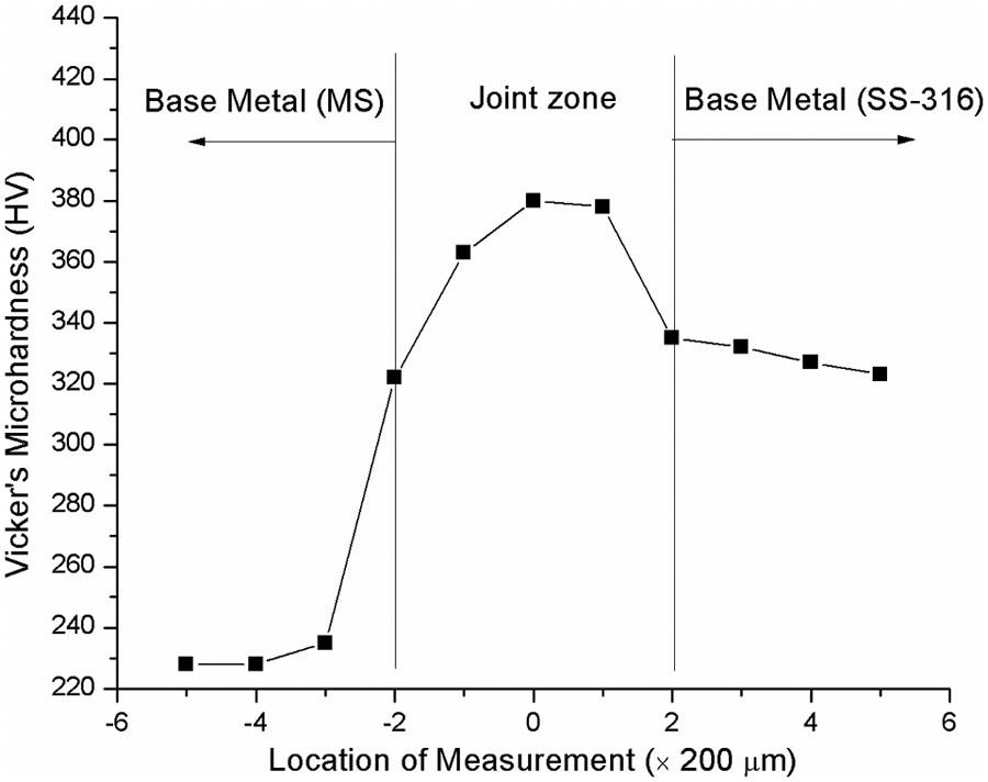
Vicker’s microhardness profile across the joint zone.
Observation on tensile strength
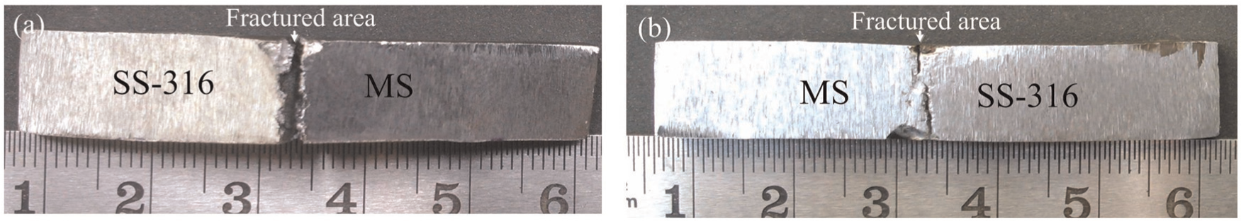
The MHH-induced dissimilar joints were further subjected to tensile test using a universal testing machine at a uniform strain rate of 0.2 mm/s. The specimens were prepared according to ASTM standard with 18 mm gauge length and 3.5 mm width. A schematic of the typical tensile test specimen is shown in Figure 8. The results obtained after performing the tests reveal a relatively low joint efficiency. The obtained joints exhibited an average ultimate tensile strength of 420 MPa with an elongation of 6.67%. The measured strength was 72.41% of base metal strength of MS (580 MPa) and it is about 80.76% in case of SS-316 (520 MPa). The failures in the dissimilar weld specimens were observed at the joint zone; this indicates that the joint zone is the weakest section as shown in Figure 9(a–c). The SEM image of the one of the fractured surface is shown in Figure 9(d), which indicates both ductile and brittle modes of failure occurred during failure of the joint. During tensile loading of the specimen, the joints fail mainly through shearing due to plastic flow of the solidified powder particles at the joint interface, but the presence of various carbides and intermetallic in the joint zone inhibited the plastic flow of material and as a result of which the microvoid formation occurs across these hard particles/matrix interfaces. These microvoids will coalesce with necking between them on further loading and lead to brittle fracture of the specimen. Thus, both ductile and brittle modes of failure occurred at the joint interfaces. Further for better understanding the tensile behaviour of the dissimilar joint, the stress–strain curve of the one of the joint specimen was plotted as shown in Figure 10. Initially up to an approximately stress of 280 MPa (point ‘A’), the joint specimen exhibits the characteristics of monolithic material and stress is proportional to strain in this part of the curve (segment ‘OA’). Furthermore, with increase in stress beyond point A, the plastic deformation in a joint specimen begins and stress required to cause plastic deformation in a material increases with increase in load. The nonlinear characteristics of the curve (segment ‘AB’) are due to strain hardening effect. During strain hardening, the joint specimen becomes harder and stronger as it was plastically deformed. The point ‘B’ corresponds to maximum stress point that can be sustained by the joint specimen in tension. However, further loading beyond point B, the joint specimen was not able to sustain increased tensile load, and finally failure of the joint specimen occurred corresponding to a stress of approximately 120 MPa (point 2‘C’). The joint specimen exhibits low percentage of elongation (∼6.67%) due to fact that the joint zone is very thin (∼700 µm) and it consists of resolidified melted powder particles and also it contains various carbide particles in the grain boundaries of the joint zone (Figure 6(a)), which hinders the dislocation movement.
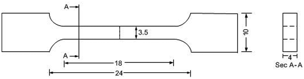
A schematic of the tensile test specimen.
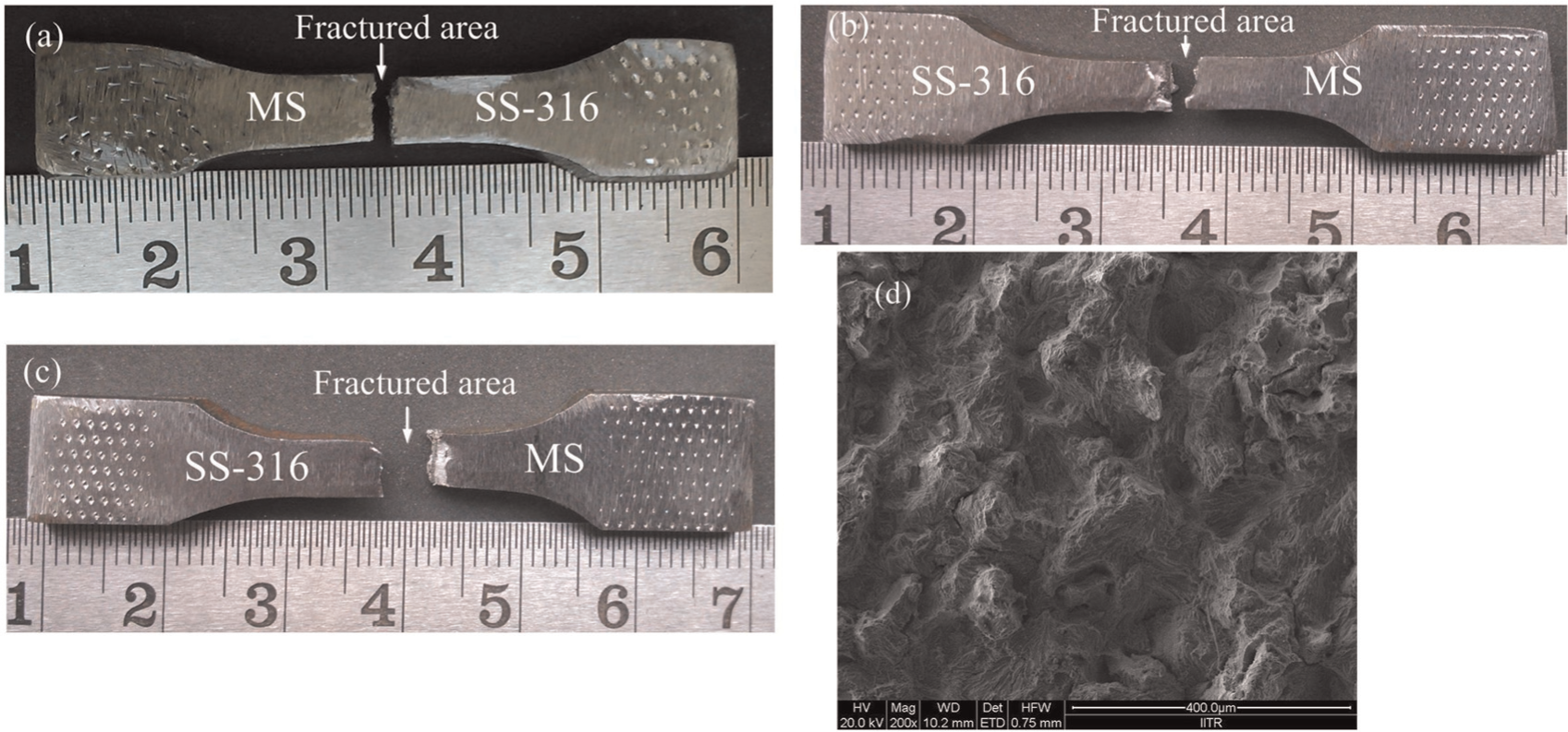
(a–-c) Optical micrographs of the fracture specimens during tensile testing. (d) SEM of the fracture surface.
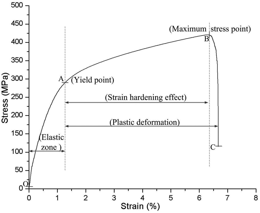
Typical stress–strain characteristics of the dissimilar joint specimen during tensile testing.
Observation on flexural strength
In order to assess the flexural strength of the dissimilar joints, the joints were subjected to standard three-point bend tests. The tests were conducted in a computer-controlled universal testing machine at a crosshead speed of 0.2 mm/min. The face bend test was carried out for determining the bending strength of the welded specimens. The optical micrographs of the failed dissimilar welded specimen during bending tests are shown in Figure 11(a) and (b). The specimens failed at the joint zone with propagation of crack along the joint zone from the face to the root of weld. For detailed interpretation of the deformation behaviour of the welded specimen during bend test, the force–extension curve was plotted for one of the tested specimen as shown in Figure 12. It was observed from Figure 12 that the welded specimen deformed elastically up to a load of ∼2220 N for phase I (segment OA) and stress is directly proportional to strain in these region of the graph. Beyond this loading, the plastic deformation in a material begins and bending stress required causing plastic deformation in the joint specimen increases with an increase in load due to strain hardening effect as shown in Figure 12 for phase II (segment AB). The point B denotes the maximum load taken by the joint specimen during bending loading. Further loading beyond point B causes initiation of crack inside the joint zone, and finally failure of the joint specimen occurred corresponding to point C. The maximum load sustained by the joints was observed to be ∼2800 N during three-point bend test with an elongation of 1.8 mm. The low ductility of the joint was due to various carbides present in the joint zone (Figure 6(a)). The average flexural strength of the joint specimen was observed to be 787.5 MPa which was 77.20% of the base material strength of MS (about 1020 MPa) and 70.94% of the base material strength of SS-316 (about 1110 MPa).
(a, b) Optical micrograph of the fracture specimens during flexural testing.
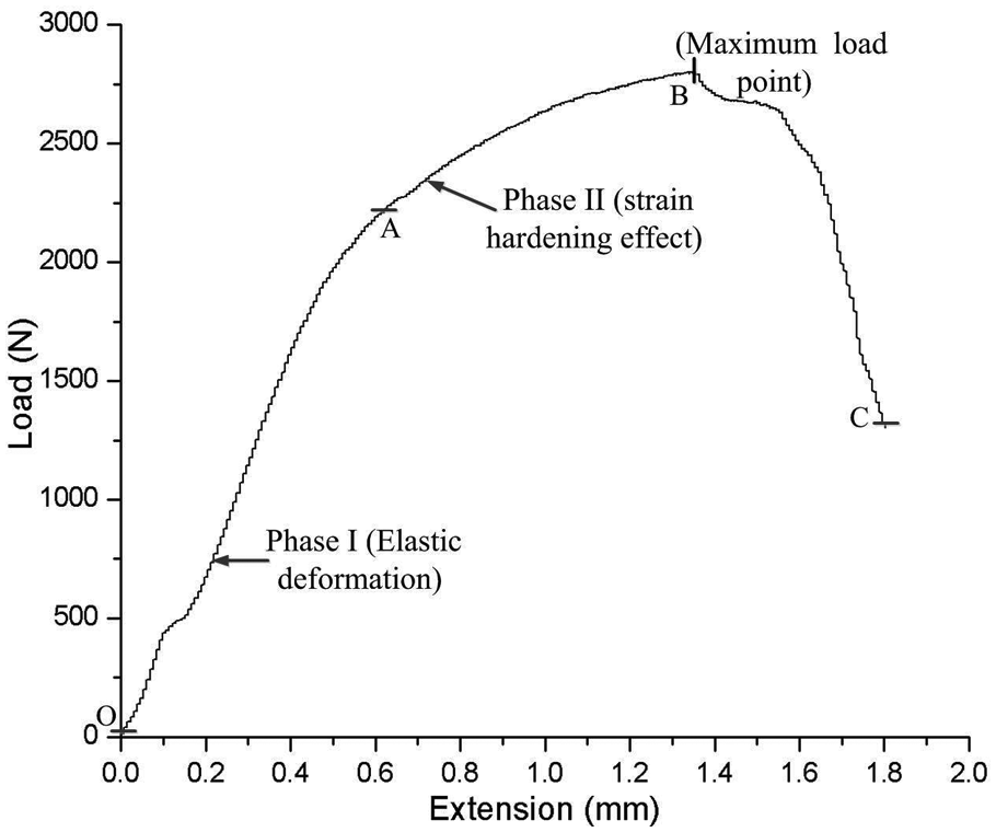
Typical load–extension characteristics of the weld specimen during flexural testing.
Conclusion
This work reports the results on development of dissimilar weld between SS-316 and MS through the principles of MHH technique. The major conclusions drawn from this work are as follows:
The principles of MHH technique could be effectively applied for dissimilar welding between MS and SS-316 substrates while using SS-316 powder as an interface layer.
The joint obtained was metallurgically bonded (fused) on either side of the base metal through complete melting of the interface powder layer.
The atmospheric heating condition favours the formation of intermetallics like NiFe2O4.
The formations of various carbides do take place in the joint zone. This is primarily due to strong affinity of metals like chromium to react with carbon at high temperature. The presence of various carbides and intermetallics is mostly observed in the joint zone.
The entire joint zone exhibits dendritic structure.
The microhardness in the joint zone is higher as compared to base metal due to the formation of dendritic structure and carbides in the joint zone during MHH.
The ultimate tensile strength of the joint was observed to be 420 MPa with 6.67% elongation. The measured strength was 72.41% of base metal strength of MS and 80.76% of SS-316.
The flexural strength of the joint was observed to be 787.5 MPa with 5.14% elongation. The measured strength was 77.20% of the base metal strength of MS and 70.94% of SS-316.
Footnotes
Declaration of Conflicting Interests
The author(s) declared no potential conflicts of interest with respect to the research, authorship, and/or publication of this article.
Funding
The author(s) disclosed receipt of the following financial support for the research, authorship, and/or publication of this article: The authors would like to express gratefulness to the Board of Research of Nuclear Sciences (BRNS) India for financing this work with project No. 2010/36/60-BRNS/2048.