
Abstract
As a versatile nanofiber manufacturing technique, electrospinning has been widely used for tissue engineering scaffold fabrication. However, it remains challenging to create scaffolds with anisotropic microstructure close to native tissues. This article presented a novel electrospinning configuration to generate fibrous mat with microstructure gradient. A series of proof-of-concept tests were performed to investigate the effects of process parameters on the gradient of nanofiber morphology and mat attributes. The technique developed in this study showed great potentials as a fabrication platform for heterogenous nanofiber products.
Introduction
With the growing demand for organ repair and replacement, a reliable alternative to the golden standard allograft has been yearned for many years. 1 Tissue engineering is an emerging cell-based approach, aiming to replace damaged tissues with in vitro generated tissue equivalents. 2 Scaffolds could mimic the extracellular matrix (ECM) of native tissue and exert certain mechanical and biological influences to modify the behavior of the cell phase. 2 –4 Among various scaffold fabrication methods, electrospinning can generate continuous sub-micrometer or nanometer fibers to form an interconnected 3D porous mat with high surface-to-volume ratio and porosity. 5 Multiple applications of electrospun nanofibers have been fabricated for biomedical applications, ranging from artificial skin to endocrine organs, from nervous system to cardiovascular applications. 6
Traditional electrospinning processes focus on fabricating random or aligned nanofibers with homogeneous structure patterns. However, most native ECMs found in tissues (e.g. sciatic nerve, bone, tendon, and cartilage) have anisotropic composition and architecture. This heterogeneous structure is considered to optimize the material’s response to external loading, 7 to enable specific cell migration during tissue regeneration, 8,9 to regulate cell growth and communication, 10 and to influence the mechanical properties. 11 It remains challenging to fabricate scaffolds with controlled gradient in nanofiber structure mimicking the natural tissues. Several methods of generating gradient scaffolds have been reported. For example, He et al. first deposited a layer with pure Poly(lactic-co-glycolic acid) (PLGA) aligned nanofibers on the cylindrical surface and then deposited a layer of PLGA/nano-hydroxyapatite aligned nanofibers on top of the previous layer. With the cylinder rotate reciprocately within 30°, the thickness is supposed to be gradient since the distance between the needle tip and cylindrical surface is changing. 12 In more complex setups, auxiliary electrodes can be added, which have been used to control the deposition location and area of the electrospun fiber, aligning nanofibers and forming simple patterns. 13 Kishan et al. combined in-line blending and air-gap electrospinning to generate compositional gradient meshes with and without fiber alignment. 14 He et al. fabricated microfiber-reinforced nanofibrous scaffolds with a gradient in nanofiber orientation for multitissue regeneration at the ligament-to-bone interface. 15
This article presents a novel electrospinning technique to create a polymer fibrous mat with microstructure gradient, which could be potentially developed as a platform for heterogeneous bioscaffold fabrication. Based on a conventional electrospinning platform, a cone-shaped rotation drum was implemented as the collector, the cone-shaped rotation collector caused a linear variation in both jet travel distance and linear rotation velocity. Unlike most of the previous works which only focus one or two attributes, the cone rotation electrospinning can simultaneously create gradient in fiber morphology, fiber diameter, fiber density, fiber alignment, scaffold porosity, and thickness. A series tests were performed to explore the appropriate process settings for gradient formation. The electrospun fiber quality is governed by many parameters, classified broadly into solution parameters (viscosity, conductivity, molecular weight, and surface tension), process parameters (applied electric field, tip to collector distance, and feeding or flow rate), and ambient parameters (humidity and temperature). 16 However, it is unclear how these parameters will influence the gradients of fiber structure attributes. The objectives of this article are to (1) determine the feasible ranges of process parameters to form the microstructure gradient and (2) to investigate the effects of critical parameters on the gradient slopes.
Material and method
Materials
Poly(vinyl alcohol) (MW = 80,000) water solution with 10 wt% concentration obtained from Tongli Tech, China, was used as the nanofiber material.
Electrospinning setup
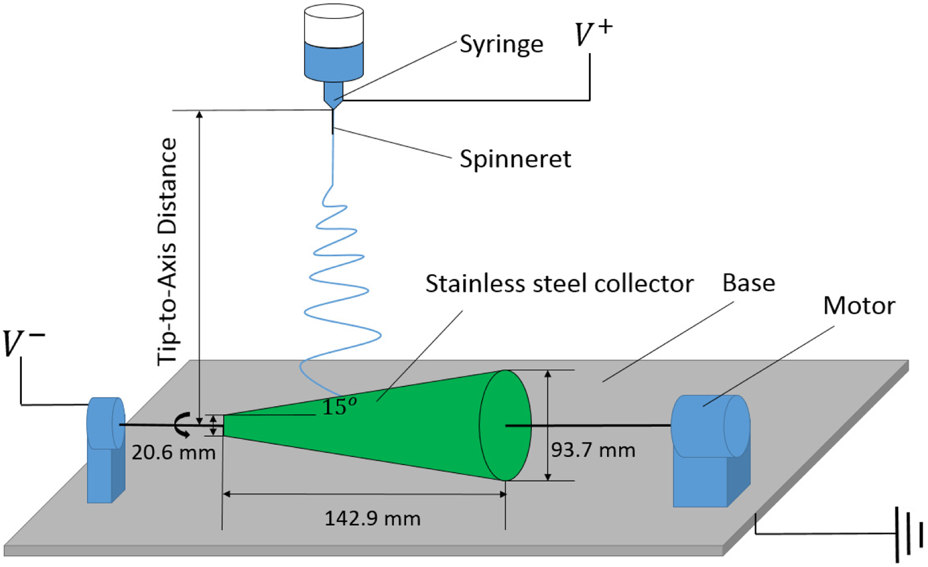
Electrospinning configuration was developed on TL-Pro-BM Robotic Electrospinning Platform (Tongli Tech, China), with 50 kV high voltage power source (Figure 1). The cone-shaped collector made of carbon steel (Fabricator Products, California City, CA, United States) was customized with a 3D printed cone-shaped disc to tuck at the narrower end of the collector. A steel cylinder with threaded holes was welded on the wider end of collector to fix it along the rotation axis. The length of the drum was 142.9 mm. The diameters of the drum were 20.6 mm on the narrower end and 93.7 mm at the wider end, resulting an inclination angle of 15°.
Cone electrospinning setup.
The cone-shaped rotation collector was connected to a negative voltage (NV) generator and placed perpendicular to the spinneret providing a linear change in fiber jet travel distance (Figure 1). A 23-gauge (0.33 mm inner diameter), flat-tipped, stainless steel needle was installed on spinneret. Polymer solution was pumped to needles by a syringe infusion pump. During the electrospinning, the syringe reciprocally scanned parallel to the rotating cone collector.
Design of experiment
In phase 1, a series of experiments were performed in a heuristic manner to explore the feasible ranges of process parameters, with which a microstructure gradient could form. Process parameters investigated with this configuration include positive voltage (PV, kV), NV (kV), the material flow rate of the polymer solution (FR, ml/h), collector rotation speed (RS, r/min), syringe scan speed (SS, mm/s), and tip-to-axis distance (TAD, mm).
Based on the results of phase 1, a two-by-two factorial design was performed in phase 2 to investigate the effects of TAD and RS on the gradient slopes of microstructure attributes, which were the rate of change in the attributes from the narrow end to the wide end. The two levels of TAD and RS were 120 mm versus 180 mm and 1000 r/min versus 3000 r/min, respectively. The PV and NV were set to be 19 kV and 1 kV, respectively. The SS was 5 mm/s and the FR of the polymer solution was 2 ml/h.
Attributes measurement
Two nanofiber samples (2 × 5 mm) were collected from the collector near the narrow end and the wide end, respectively. The nanofiber morphology was examined by scanning electron microscopy (SEM), with 450, 700, and 1.8 K magnifications. There were four attributes measured for each sample: fiber diameter, fiber density, mat porosity, and fiber alignment.
Fiber diameter was analyzed by DiameterJ (1.48) after the SEM image was segmented and processed. Fiber density was characterized by counting the number of fibers that intersected a line drawn across the middle of a binary SEM image so that only the top layer of the mat was counted. The porosity of the samples was estimated by calculating the percentage of void space in the SEM image after it was segmented. Fiber alignment was characterized by the standard deviation of all acute angles between the visible fibers and the horizontal line in the middle of the image. In phase 2, analysis of variance (ANOVA) and linear regression model were performed using R (3.4.1) to detect the statistical significance at level of α = 0.05 with a sample size of 4.
Results
The electrospun mats in phase 1 were first visually examined after the experiment. The results and corresponding parameter settings are summarized in Table 1. Some of the mats showed obvious color gradient from white to transparent (Figure 2). The degree of color gradient decreased as the TAD increased.
Parameter settings and visual inspection results.

FR: flow rate; NV: negative voltage; PV: positive voltage; RS: rotation speed; SS: syringe scan speed; TAD: tip-to-axis distance.
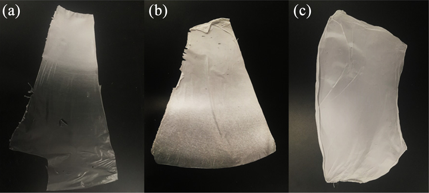
Electrospun mats with color gradients. The white section is near the narrower end and the transparent section is near the wider end (a, b, and c are from exp. #1, #7, and #12, respectively).
However, the SEM images revealed that the transparent sections of the mats were non-porous thin films without fibrous structure. Images of samples from exp. #7 and #12 are presented in Figure 3. It showed that a minimum of TAD was required to form the nanofibers. Meanwhile, the mats without obvious color gradient demonstrated microstructure gradient in terms of nanofiber diameter and density. Based on the results of phase 1, we hypothesized that TAD and RS were the two critical parameters that influence the microstructure gradient.

Representative SEM images of nanofibers from phase 1 experiments: (a) Near the narrow end of exp. #7, (b) near the wide end of exp. #7, (c) near the narrow end of exp. #12, and (d) near the wide end of exp. #12. Scale bar = 10 µm. SEM: scanning electron microscopy.
The SEM images of samples in phase 2 are presented in Figure 4. The diameter distributions are summarized in Figure 5. All samples showed nanofibrous structures with fiber diameter ranging from 161 nm to 540 nm. The consistency of fiber morphology enhanced as the TAD increased from 120 mm to 180 mm. The fiber attributes varied among different groups.

SEM images of nanofiber samples from phase 2 experiments: (a) 120 mm, 1000 r/min, narrow end; (b) 120 mm, 1000 r/min, wide end; (c) 120 mm, 3000 r/min, narrow end: (d) 120 mm, 3000 r/min, wide end; (e) 180 mm, 1000 r/min, narrow end: (f) 180 mm, 1000 r/min, wide end; (g) 180 mm, 3000 r/min, narrow end; and (h) 180 mm, 3000 r/min, wide end. Scale bar = 10 µm. SEM: scanning electron microscopy.

Nanofiber diameter distributions from phase 2 study: (a) 120 mm, 1000 r/min, narrow end; (b) 120 mm, 1000 r/min, wide end; (c) 120 mm, 3000 r/min, narrow end; (d) 120 mm, 3000 r/min, wide end; (e) 180 mm, 1000 r/min, narrow end; (f) 180 mm, 1000 r/min, wide end; (g) 180 mm, 3000 r/min, narrow end; and (h) 180 mm, 3000 r/min, wide end.
The gradient (rate of change from the narrow end to the wide end) in four attributes, namely the fiber diameter, fiber density, fiber alignment, and porosity of these four groups is summarized in Figures 6 to 9, respectively. The results of the ANOVA are summarized in Table 2. The TAD has a significant effect on fiber diameter gradient and a marginal effect on fiber density gradient. The RS has a significant effect on porosity gradient. The interactive effect of TAD and RS has significant effects on porosity gradient and fiber alignment gradient. These effects were quantified by linear regression models which are presented in equations (1) to (3).

Fiber diameter gradients.

Fiber density gradients.

Porosity gradients.

Fiber alignment gradients.
ANOVA results for the gradients.

ANOVA: analysis of variance; RS: rotation speed; TAD: tip-to-axis distance.
*p < 0.05.
#p < 0.1.
With TAD = 120 mm, the fiber diameter gradient was –0.13 for RS = 1000 r/min and –0.07 for RS = 3000 r/min, indicating the average fiber diameters decreased from the narrow end to the wide end by approximately 13% and 7%, respectively. With TAD = 180 mm, however, the gradient was 0 for RS = 1000 r/min and –0.02 for RS = 3000 r/min, indicating that no remarkable change in diameter was observed.
The ANOVA showed that the fiber diameter gradient solely depended on the TAD. The linear regression model was given as follows:

The fiber density gradient appeared to be opposite to fiber diameter gradient. With TAD = 120 mm, the gradient increased for all two RS levels, indicating that the fiber counts increased from the narrow end to the wide end by 5–10% depending on the RS. With TAD = 180 mm, the gradient was decreased: –0.02 for RS = 1000 r/min and 0.02 for RS = 3000 r/min. The ANOVA showed that none of these two factors has a significant effect on the fiber density gradient.
The gradient of mat porosity did not appear to be a simple combination of those of fiber diameter and fiber density. With TAD = 120 mm and RS = 1000 r/min, no remarkable gradient (–0.01) was observed. The porosities at the narrow end and the wide end were very close. When RS increased to 3000 r/min, however, the porosity increased by 24% from the narrow end to the wide end. With TAD = 180 mm, the porosity increased by 7–10%, from the narrow end to the wide end depending on the RS. ANOVA showed that the porosity gradient was significantly influenced by the RS and interaction of RS and TAD. The linear regression model was given as follows:

When both TAD and RS were low (120 mm and 1000 r/min), the fiber alignment gradient was 0.42, suggesting that the fibers at the wide end were more aligned than those at the narrow end. Similarly, an obvious alignment gradient (0.39) was observed when both TAD and RS were high. However, on the other two cases, the alignment gradient was substantially diminished. ANOVA showed that the alignment gradient was significantly influenced by the interaction of TAD and RS, meaning that the effect of TAD on the gradient depends on the RS, and vice versa. The linear regression model was given as follows:

Discussion
The cone electrospinning presented in this article was able to create nanofiber mats with gradient in multiple microstructure attributes simultaneously. More importantly, many of these gradients can be controlled through the process parameters. Based on phase 1 study, we found that the fiber morphology was largely influenced by TAD and RS. With the proposed cone geometry and material, the minimal values of TAD and RS to generate high-quality fibers were found to be 100 mm and 1000 r/min, respectively. FR mainly affect the volume of fibers electrospun from the nozzle per unit of time. With a certain level of voltage, RS should be adjusted to the optimal range to maintain a stable electrospinning without excessive flow. In addition, changes of NV and SS did not substantially affect the fiber morphology.
Phase 2 study showed that the fiber diameter gradient was dominated by the TAD. It is widely accepted that the fiber diameter of a specific solution is negatively correlated to the jet travel distance in a given electric field. 17,18 However, our study showed that when TAD is low, the fiber diameter tended to decrease from the narrow end to the wide end despite of the decrease in jet travel distance. While TAD is high, the gradient was largely diminished. One of the unique characteristics of the rotation electrospinning, which tends to be ignored, is that the linear velocity of the drum surface, namely linear surface velocity (m/s), can substantially influence the fiber diameter. 19 –21 The surface velocity may determine whether and how the fibers deposited on collector will be stretched, and thus influence the fiber diameter and alignment.
In traditional rotation electrospinning with a cylinder drum, the surface velocity and RS (r/min) are interchangeable. In our case, however, the gradient of the drum diameter resulted in a continuous change in both jet travel distance and surface velocity along the drum axis, which caused two contradict impacts on the fiber diameter. Theoretically, from the narrow end to the wide end, a decrease in jet travel distance may enlarge the fiber diameter, while an increase in surface velocity, in contrast, may reduce the fiber diameter. When TAD was low, the effect of surface velocity overcame the effect of jet travel distance, resulting in a decrease in fiber diameter. It is also noted that when the RS increased from 1000 r/min to 3000 r/min, the gradient was reduced. This was potentially due to the diminished marginal effects of the surface velocity on the fiber stretching. When TAD was high, the average fiber diameter at the narrow end was already very small (400–500 nm), approaching the limit of the given solution due to its physical and mechanical properties. Therefore, the surface velocity had little impact on the diameter gradient.
For fiber density, previous works argued that a longer jet travel distance would give the fiber more time to evaporate and split, thus generates more fibers. 22,23 However, in our study, with low TAD, the fiber density increased from the narrow end to the wide end by 5–10%. This could be highly related to the change of fiber diameter. With a constant FR, the same amount of solution was essentially fabricated into different fibrous forms. The fiber count was thus negatively correlated to the fiber diameter.
Generally, the mat porosity would enhance from the narrow end to the wide end because of an increase in the deposition area. This gradient was positively correlated to the RS. When TAD was low, the effect of RS on the porosity gradient was strong; but when TAD was high, the effect weakened due to the reduced electric field intensity, which resulted in a low fiber density and a high porosity at both narrow end and wide end. The gradient was thus lessened.
The fiber alignment gradient was maximized when both TAD and RS were low or high. This phenomenon strongly suggested that a proper combination of TAD and RS is required to have fiber alignment gradient. The fiber alignment in the rotating electrospinning is largely determined by the relationship between the surface velocity of the drum and the fiber jetting rate. With a given fiber jetting rate, there will be an optimal range of surface velocity, with which the fibers will be rolled up onto the collector immediately after it falls on the collector without break, forming with a circumferential manner. 20,24 However, if the surface velocity does not match the fiber jetting rate, the fibers may be randomly deposited on the collector.
Although this study only adopted a single design of the cone collector, we conjecture that the geometry of the cone collector may also influence the fiber attributes. For example, the gradient degree of the fiber attributes may be positively correlated to the inclination angle of the cone because an increase in the inclination angle will result in a greater change ratio in TAD and RS, respectively. However, if the inclination angle is exceedingly large while the length of the collector is relatively short, the solution may be electrospun only onto the wide side of the collector due to the unbalanced electric potential differences. Therefore, the system configuration needs be properly designed to ensure the fiber quality and attribute gradients.
The possibility of fabricating gradient scaffold via electrospinning for biomedical applications is explored in this article. This proof-of-concept study showed the feasibility of creating nanofiber mat with gradient in multiple attributes. This technique may provide novel resolutions for biomedical engineering, drug delivery, air/water filtration, advanced sensor systems, and so on. A comprehensive parametric study and a computational modeling on process parameters and cone geometry parameters are needed to elucidate the mechanisms of gradient formation. The control mechanism of gradient attributes also needs to be further studied. Furthermore, it will be of great interest to develop 3D manufacturing methods for heterogenous nanofiber products based on this conceptual design.
Conclusion
This article presented a novel cone rotation electrospinning technique for gradient nanofiber mat fabrication. The pilot study showed that the TAD and RS influenced the degree of gradient in multiple attributes, including fiber diameter, mat porosity, and fiber alignment. Future parametric and mechanism studies are needed to establish the quantitative relationships between the process parameters and the attribute gradients.
Footnotes
Declaration of conflicting interests
The author(s) declared no potential conflicts of interest with respect to the research, authorship, and/or publication of this article.
Funding
The author(s) received no financial support for the research, authorship, and/or publication of this article.