
Abstract
In the present work, the synergistic effect of multiwalled carbon nanotubes and glycidyl polyhedral oligomeric silsesquioxanes on the compression after impact behaviour of multifunctional carbon fibre–reinforced epoxy composite plates is investigated. For the qualitative evaluation of the damage accumulation after impact, non-destructive ultrasonic C-scan tests were performed. The impact-induced material degradation was correlated with data obtained from C-scan graphs through applying the concept of the damage severity factor. The test results obtained from C-scan analysis have shown a significant increase of the damaged area after the impact tests, as compared to the unfilled material considered as ‘reference’. A reduced compression after impact strength is observed for the enhanced material as compared to the reference material. To identify the type of damage, optical microscope, scanning electron microscope and energy dispersive spectroscopy analyses were made after the tests. The optical microscope analysis has shown more extended cracking and delaminations for the enhanced material. Scanning electron microscopic analysis has revealed the presence of carbon nanotube agglomerates and possible glycidyl polyhedral oligomeric silsesquioxanes aggregates which might be the cause for a degraded compression after impact behaviour of the multifunctional composites.
Keywords
Introduction
The progress accumulated over several decades on the technologies of carbon fibre–reinforced polymers (CFRPs) led to a dramatic increase in the use of composites in modern civil aircraft primary structures. However, composite materials lack electrical conductivity and flame resistance, which are important features for aircraft safety. To face the lack of electrical conductivity as well as the poor flame resistance of composites necessitates the development of improved materials and innovative technologies.
In order to improve the electrical conductivity of both polymers and fibre-reinforced polymers, several efforts are in progress to reinforce them with different forms of nanostructured carbon, such as multiwalled carbon nanotubes (MWCNTs). Previous investigation has shown that MWCNTs have definite advantages for the realization of composites with improved electrical conductivity and remarkable mechanical properties such as impact resistance and vibration damping. 1 –3 On the other hand, the flame resistance of polymers or fibre-reinforced polymers can be significantly enhanced with the incorporation of a specific type of polyhedral oligomeric silsesquioxanes, glycidyl polyhedral oligomeric silsesquioxanes (GPOSS). 4 However, modification in the materials structure is associated with changes in the mechanical properties of the materials and hence in their structural performance.
In the studies by Chang 5 and Davis et al., 6 the effect of MWCNTs on the tensile behaviour of CFRPs has been studied. At a concentration of 0.5%, Chang 5 found that the tensile strength was increased over 30% as compared to the unfilled material. Further increase of the concentration led to a slight decrease of the tensile strength. The author assumed that the reason for this decrease may be due to the MWCNT agglomerates in the matrix causing a poor interface between MWCNT and matrix.
It is worth noticing that during service of aircraft structures, a variety of impact events, such as tool drops, runway debris, ground vehicles and equipment, bird strike, hailstones, maintenance actions, lightning strikes, and so on, may occur. 7 As a result, an extensive internal damage may occur with or without visible traces on the impacted area depending on the impact velocity and energy. This is expected to lead to a strength degradation of the structure. 8
As far as the compression after impact (CAI) behaviour of composites filled with CNTs is concerned, Ashrafi et al. 9 studied the CAI behaviour of carbon fibre/epoxy laminates enhanced with 0.1% (by weight) of Single Wall Carbon Nanotubes (SWCNTs). A 5% reduction in the damaged area after impact was found. The CAI strength was increased by 3.5%; however, the standard deviation was more than 4.5%. The influence of MWCNTs in CAI behaviour has also been investigated by Kostopoulos et al., 10 where impact tests were conducted at different energy levels (2, 8, 12, 16, and 20 J). The delamination area after impact was found reduced, while the CAI strength was increased around 12–15% for the doped specimens.
On the other hand, a degraded CAI behaviour was found in the literature. 11 –13 Siegfried et al. 11 investigated the CAI behaviour of woven carbon fibre/epoxy composites enhanced with MWCNTs. In all cases, a CNT content of 0.25% (by weight) was diluted in the epoxy matrix. The results showed an increase of the delaminated area after impact for the filled materials as compared to the delaminated area observed for the unfilled material. The residual compressive strength was either similar to the one observed for the unfilled material or decreased. Microscope results showed extensive matrix cracks for the enhanced material. Therefore, it was assumed that CNTs may act as stress concentrators rather than as reinforcement due to the CNT agglomeration during dispersion.
Furthermore, studies 14,15 on the low-velocity impact behaviour of woven laminate composites reinforced with functionalized MWCNTs showed an increase in the damaged area after impact of the composites enhanced with MWCNTs as compared to the unfilled material. Specifically, Taraghi et al. 14 investigated the low-velocity impact response of composites enhanced with 0.3, 0.5 and 1.0% (by weight) MWCNTs. The same energy level of 45 J was sustained in all impact tests. The extent of the damaged area in the back side of the specimens for the composites enhanced with 0.5% (by weight) MWCNTs was reduced as compared to the neat specimens. On the other side, the addition of 1.0% (by weight) MWCNTs resulted in a larger damaged area. The author yielded the increase in the damage development to the existence of nanotubes agglomerates.
As far as the electrical conductivity is concerned, it is found that the electrical percolation threshold, that is, the transition from the insulating to conducting electrical behaviour, is reached for an MWCNTs concentration value ranging between 0.1% and 0.32% (by weight). 16
The incorporation of a flame retardant into the polymer matrix addresses the need for flame resistance in the exterior polymer composite structures of aircrafts. POSS are hybrid inorganic/organic compounds with an inner inorganic core, which is occupied by the silicon and oxygen components and external organic substituents that make them compatible with most polymers. Raimondo et al. 4 studied the flame retardancy properties of enhanced epoxy systems with 5% (by weight) POSS compounds by measuring the limiting oxygen index (LOI) and the peak heat release rate (PHRR). High LOI and low PHRR values evidence a flame-resistant material. The GPOSS compound was proved to be the most promising flame retardant to enhance the resin. The results showed an LOI value of 33 and a PHRR value of 327 KW/m2 as compared to 27 and 540 KW/m2 of the unfilled resin, respectively.
Furthermore, Fina et al. 17 investigated the effect of the addition of three different types of polysilsesquioxanes (PSS) in polypropylene on the tensile behaviour. Methyl (Me)-, vinyl (Vi)- and phenyl (Ph)-PSS were blended into the polymer matrix. POSS were loaded into the polymeric matrix at 1.5 and 5% of inorganic fraction. The tensile test results showed an increase in the elastic modulus and the yield stress for the Vi-PSS, which retained its homogeneity in the filled state. Due to the presence of aggregates of POSS compounds or the observed local concentration of the POSS substituents into the polymer, Me- and Ph-PSS exhibited a degraded tensile behaviour as compared to the unfilled material. The author stated that both the PSS dispersion and the nature of substituent are influencing the mechanical behaviour; in particular, a more improved flame resistance as well as tensile behaviour was obtained with Vi-PSS, which is attributed to the homogeneous dispersion.
Nevertheless, investigations available in the open literature on the mechanical behaviour of composite materials enhanced with both MWCNTs and flame retardant remain up to now very limited. In the study by Polydoropoulou et al. 18 , the effect of both CNTs and flame retardants on the mechanical behaviour of an epoxy polymer RTM6-2 subjected to several types of quasi-static loading was investigated. The results have shown a significant increase for the tensile strength of the polymers filled only with MWCNTs as compared to the unfilled material. However, the other properties, namely compression, flexural as well as Critical strain energy release rate (GIC) fracture toughness properties, were degraded. The incorporation of the flame retardant GPOSS into the polymer has further deteriorated the mechanical behaviour of the filled material, which was attributed to the large CNTs and GPOSS agglomerates over 100 μm revealed by scanning electron microscopy (SEM) inspection.
In the present work, the CAI behaviour of carbon fibre–reinforced epoxy composite plates, which are enhanced with MWCNTs and a viscous liquid, GPOSS as flame retardant, is assessed through CAI mechanical tests. The same tests were carried out also to unfilled material considered here as ‘reference’. The results are supported by non-destructive ultrasonic C-scan investigation to evaluate damage accumulation after the impact. Furthermore, optical microscopy, SEM and energy dispersive spectroscopy (EDS) analyses were carried out to support a better understanding of the results obtained from the mechanical tests.
Materials and specimens
The materials used for this study have been carbon fibre–reinforced epoxy composite plates enhanced with 0.5% (by weight) MWCNTs and 5% (by weight) viscous liquid GPOSS functionalized with oxirane rings. In order to make a comparison feasible, unfilled material has also been used, referred to hereafter as reference.
The matrix formulation is based on a tetrafunctional epoxy precursor ((tetraglycidylmethylenedianiline (TGMDA)) under the commercial name RTM6-2, 19 which is a two-component resin designed to fulfil the requirements of the aerospace industry. The operation service temperatures range from −60°C up to 120°C. However, the resin used in this study differs from the commercial one since only one type of hardener is used, instead of a mixture of hardeners used in the commercial resin.
The epoxy matrix of the composite has been prepared by mixing a TGMDA with epoxy reactive diluents 1-4 butanediol diglycidyl ether (BDE) at a concentration of 80%:20% (by weight) combined with 4,4’ diamminodifenilsolfone, as hardener.
An ultrasonication for 20 min has been used in order to achieve a uniform dispersion of 0.5% (by weight) MWCNTs within the epoxy matrix. This concentration offers sufficient electrical conductivity to composite aerostructures resulting to an effective dissipation of lightning currents during flight, 16,20 while the mixture is characterized by good dynamic mechanical properties. 21 MWCNTs are NANOCYL NC3100 series thin MWCNTs, with an average diameter of 9.5 nm and an average length of 1.5 µm. The carbon purity is greater than 95% with a metal oxide impurity lower than 5%.
The GPOSS compound was dispersed at a percentage of 5% (by weight) in the epoxy matrix. An ultrasonication of the GPOSS inside the liquid epoxy formulation had preceded the magnetic stirring at 120°C in order to obtain optimal dispersion and eliminate the residuals. 4 In this case, the POSS nanoparticles are bonded covalently with polymer. 22 Consequently, the final formulation of the epoxy matrix is as follows:

The formulations of the resin have been produced by the University of Salerno and the company NANO 4, Belgium in the frame of the Improving the Aircraft Safety by Self Healing Structure and Protecting Nanofillers (IASS) project. 22 In this context, this work was based on predefined material formulations that did not include the production of material involving each additive separately. Therefore, the investigation of the effect of each separate additive on the CAI behaviour of the composite could not be carried out.
The production of the composite panels was held at the Italian Aerospace Research Centre in cooperation with the University of Salerno. The composite panels were manufactured via the resin film infusion process using an unusual technique to infuse the nanofilled resin into a carbon fibre dry preform in order to overcome low viscosity values drawbacks. It is based on the infusion of a viscous resin on the preforms with the use of a vacuum bag under pressure. The laminates produced consist of 24 plies of a plain weave carbon fibre fabric (SIGMATEX (UK) LDT, UK 193GSM/PW/HTA40 E13 3 K) with a [0°/90°] stacking sequence. The volume fibre content of the laminates is 65 ± 2%.
For the CAI tests, rectangular specimens of 150 × 100 mm2 were used. The specimen thickness was 4 mm with a deviation range of ± 0.25 mm. In total, 16 specimens were extracted from the panels. In the present work, a series of eight filled and eight unfilled specimens serving as reference have been investigated.
Experimental investigation
Impact tests
The impact tests have been conducted according to the specification standard ASTM D7136. 23 This test method determines the damage resistance of composite plates subjected to a drop-weight impact event. All impact tests have been carried out using an Instron Dynatup (INSTRON, Norwood, Massachusetts) drop tower with a hemispherical striker tip. The specimens were fixed with the use of four clamps on each side, as shown in Figure 1. The specimens have been subjected to low energy impact level, ranging from 25 J to 30 J. By the subsequent evaluation, the energy losses due to friction during drop were neglected.
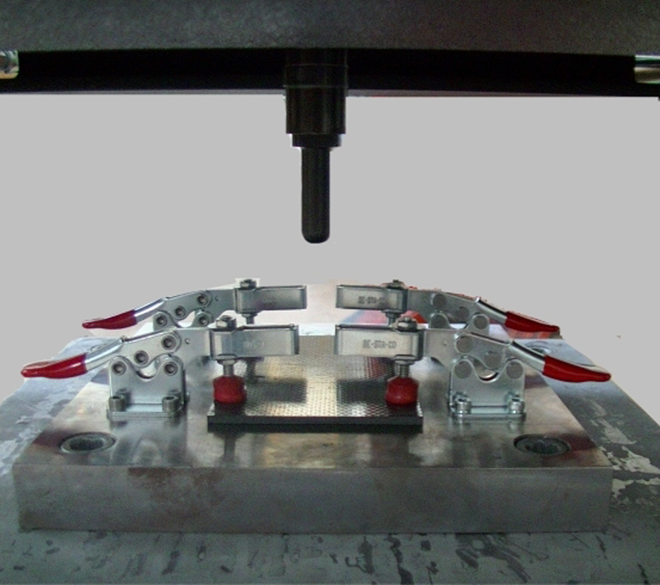
Impact device.
C-scan evaluation
Prior to impact, all specimens were subjected to C-scan analysis. The specimens have been examined using the Ultrapac ultrasonic system (MISTRAS Group, Princeton Junction, NJ) and the Ultrawin software [V2.83, Mistras Group]. A transducer of 10 MHz focused at approximately 20 mm has been used in order to obtain more precise results. All specimens have been evaluated for the detection of initial damage.
Following to impact testing, the induced damage was initially detected through visible observation. Then, all specimens were subjected to a second C-scan evaluation using the equipment and the parameters described earlier to detect possible delaminations, matrix cracks and extended fibre cracking caused by the impact. To evaluate the C-scan results, an image analysis software was used. To make a quantitative comparison of the outcome of the C-scan analyses manageable, the impact-induced material degradation is correlated with data obtained from C-scan graphs through the concept of the damage severity factor (DSF). 24 DSF accounts for the varying severity of damage at different specimen locations. According to the earlier concepts, the ultrasonic signals and the severity of local damage may be correlated by a one-to-one relationship. For the correlation, a linear expression has been used. The damage parameter DSF is given by
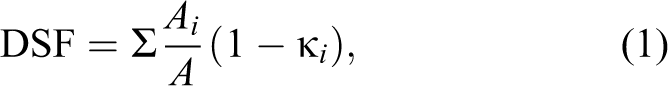
where A is the total specimen area, Ai is the area monitored by C-scan for a given damage state and ki is the damage severity of the area Ai .
In the study by Pantelakis et al. 24 , DSF values were related to residual properties of composite laminates subjected to fatigue. In this work, the derived DSF values were related to residual compressive strength.
CAI tests
Following to impact testing, the specimens were subjected to compression to determine the residual strength. For the determination of the residual strength properties of the impacted composite plates, the equipment used and the procedure followed meet the specifications according to the specification standard ASTM D7137. 25 Compression testing has been performed using an MTS servohydraulic test machine with a capacity of 250 kN. For the installation of the composite plates, a stabilization device to minimize loading eccentricities and induced specimen bending has been used, as shown in Figure 2. 25 The stabilization fixture is composed of multiple adjustable pieces that prevent from out-of-plane displacements. For the compression test, the specimen was placed in the fixture, and a compressive force was applied until a maximum force was reached and the load has dropped off about 30% of the maximum. Acceptable types of damage pass through the damage induced from the impact test in the test specimens, meaning that the damage shall be met across the center line of the specimen in the lateral direction.

Compression stabilization fixture.
Optical microscopy
After the compression test, optical microscope evaluation was made to identify the damage features. The area of interest is the center cross section, where the impact strike has taken place as well as the cross section out of the boundaries of the impact damage. For the evaluation, specimens from both, reference as well as filled materials, were sliced into stripes.
SEM and EDS analyses
The results of the mechanical tests were discussed and supported by SEM and EDS analyses. The SEM inspection was performed using a Zeiss SUPRA 35VP model (Carl Zeiss AG, Jena, Germany). Concerning the technical data of the microscopy, a 1.7-nm resolution at 15-kV accelerating voltage in the high vacuum mode was used. The samples were gold coated (Baltec 005 sputter coater, BalTec AG, Pfäffikon, Switzerland) in order to avoid surface charging. The elemental chemical analysis was performed in situ during the SEM microscopy. The SEM microscope was equipped with an EDS analyzer measuring the energy or wavelength distribution of the X-ray signal generated by the electron beam.
Results and discussion
Impact tests
The mean contact force–time and energy–time curves recorded during the impact test of all specimens are illustrated in Figure 3. The graphs show a typical impact behaviour of composite plates as it can also be found in the literature. 9,10,13,26 –28 In Figure 3(a), almost the same values are observed for the first discontinuity in contact force as well as the peak contact force of both materials. However, the filled material shows systematically longer contact duration than the reference material. This duration discrepancy is likely due to creation of more damaged areas in the case of the filled material. 11 After the peak force, a more rapid load drop is observed in the case of the reference material as compared to the filled one. Concerning the energy versus time results, as shown in Figure 3(b), slight differences are observed. After the maximum impact energy value is reached, a slight drop leading to a constant energy is observed for both materials, reference and filled. The constant energy observed coincides with the absorbed energy by the specimens. 26,27 The percentage of the energy absorption with regard to the impact energy given was 96 and 93% for the reference material and the filled material, respectively; the deviation in both cases has not exceeded 3.5%.

(a) Force–time and (b) energy–time curves for both materials, reference and filled.
The results from the impact tests for both materials are given in Table 1. Each specimen is indicated with a sequence number at the first column of Table 1 and the rest columns show results concerning the maximum load and impact velocity, as well as the nominal and absorbed energy.
Impact results.

Note: The italics values provide the average values and the standard deviation of the results.
Permanent damage occurs after the impact test, such as indentation, delamination, matrix cracking and fibre breakage, as indicated also in the studies by Kim et al.7 and Kan. 8 Most of these deformations are visible through naked eye. A visible dent has been formed at the impacted (front) surface area, as it is shown in Figure 4(a). At the back side of the specimens, fibre breakage is obvious (Figure 4(b)). A similar type of damage is exhibited in both materials, reference and filled.
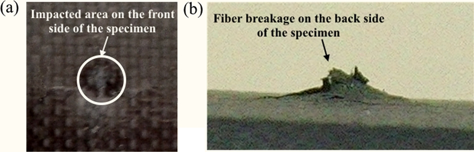
(a) Impacted area and (b) Back side of the specimen.
C-scan evaluation
The internal damage has been detected through C-scan analysis; representative results are illustrated in Figure 5. The graph refers to a reference (Figure 5(a) to (d)), as well as a specimen enriched with MWCNTs and GPOSS (Figure 5(e) to (h)) before and after impact test. As it can be seen in Figure 5, the red central circle indicates the damage caused by the impactor for both specimens. Yet, in the case of the enriched material, the damage also expands out of the boundaries of the impacted area. A distinct increase in damaged area is shown in the case of the material enriched with MWCNTs and GPOSS. According to C-scan graphs, the damaged area calculated as 640 ± 106 mm2 and 1090 ± 174 mm2 for the reference material and the filled material, respectively. Based on a statistical analysis using t-test’s statistical significance with 95% confidence level, the calculated p-value was 0.000, which indicates a significant increase for the measured damaged area of the filled material as compared to the unfilled one.
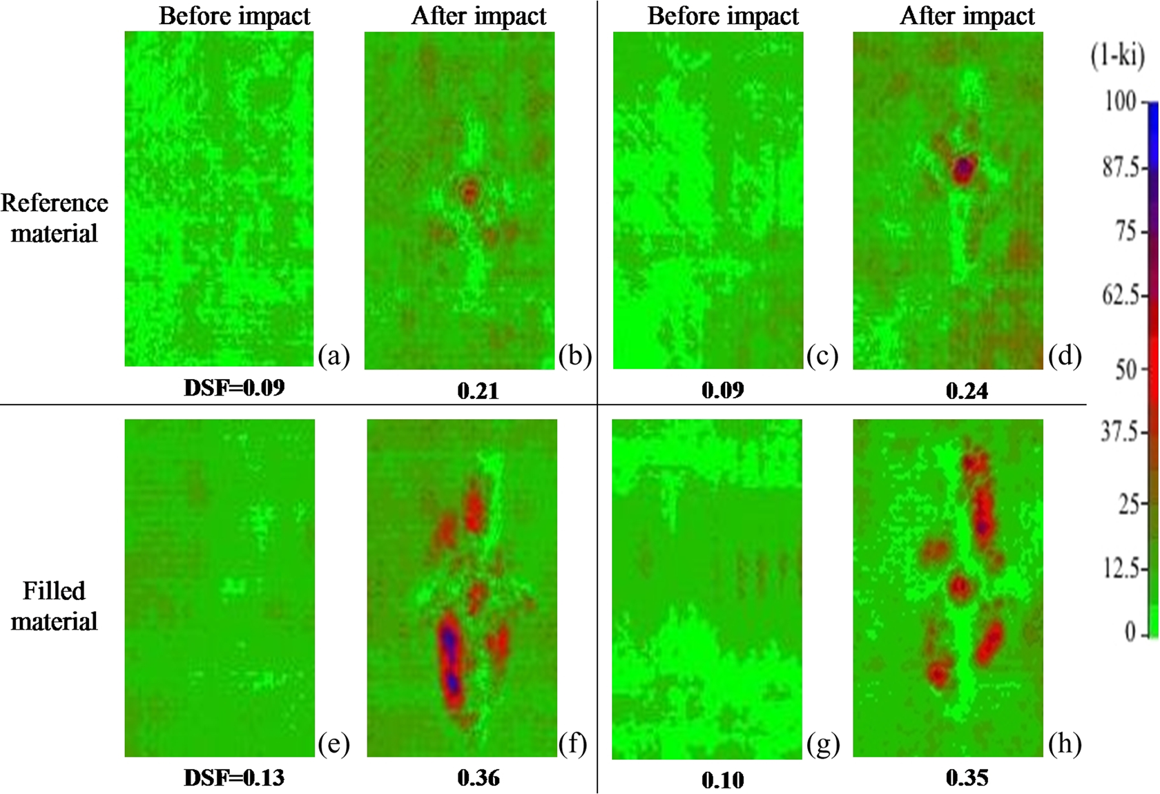
C-scan graphs and corresponding DSFs of (a) to (d) reference material before and after impact as well as (e) to (h) filled material before and after impact. DSF: damage severity factor.
The results in Figure 5 allow to compare the damaged areas of the impacted specimens, yet they do not account for the severity of the observed damage. An assessment of the damage severity caused by the impact tests can be made by involving the DSF concept proposed in the study by Pantelakis et al. 24 The parameters in eqation (1) were derived using an image analysis software.
The calculated DSF values are given in Table 2 at the state ‘before impact’ and ‘after impact’ of both reference as well as filled materials. Each specimen is indicated with a sequence number at the first column of Table 2. In Figure 5, the calculated DSF values are matched to the corresponding C-scan graphs; the damage severity (state) ‘1−ki ’ is obtained according to the color palette scale. The results refer to a 70 × 50 mm2 portion of the specimen, from the total specimen geometry of 150 × 100 mm2. The red central circle was set as the reference center, which corresponds to the impacted area. The calculations performed exhibit a similar DSF for the undamaged specimens of both materials, reference and filled. A 30% increase is found for the damage severity of the filled material after impact.
DSF before and after impact of both reference and filled materials.

DSF: damage severity factor. Note: The italics values provide the average values and the standard deviation of the results.
Recall that the energy absorbed by the filled material is equal or less than the impact energy absorbed by the reference material. It contradicts the observation of increased impact damage for the filled specimens. To explain this, observation is justified to assume that the addition of the nanofillers (MWCNTs and GPOSS) facilitates damage to accumulate and to spread. The observed increase of the damaged area in the case of the enhanced with MWCNTs material is consistent with results from the literature. 11,12 According to Siegfried et al., 11 CNT agglomerations were assumed to act more like rigid inclusions and stress concentrators supporting damage evolution. Still, in the case of a possible incomplete dissolution, the GPOSS residuals into the polymer matrix may also reduce the mechanical properties of the filled material, as it is indicated in the study by Fina et al. 17
Optical microscopy
A deeper observation at microscale has revealed the damage seeded from the impact event. Taking also into account the obtained results from C-scan graphs, a more extensive damaged area out of the boundaries of the impacted area is expected in the case of the material enhanced with MWCNTs and GPOSS. The shots are taken after the CAI tests; however, the damage origin of the impact event remains obvious.
Figure 6(a) illustrates the undamaged state, while Figure 6(b) and (c) depicts a widespread damage within (Figure 6(b)) and out (Figure 6(c)) of the impact boundaries. At the impacted area, fibre breakages, multiple matrix cracks and delaminations are introduced in both materials, as shown in Figure 6(b). In the case of the reference material, the impact induced limited cone shape damage with extensive delaminations and fibre breakages. Considering the area out of the impact boundaries (Figure 6(c)), the traces of the impact damage are obvious in the case of the filled material; fibre breakages and matrix cracks are shown in Figure 6(c).
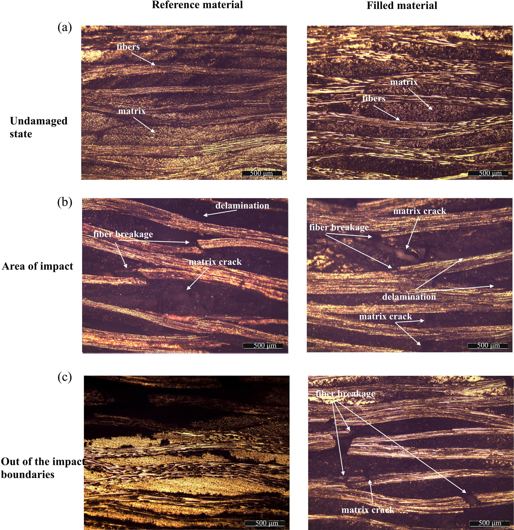
Optical microscope images of reference and enriched material after impact and CAI. (a) Undamaged cross section, (b) central cross section, (c) out of the boundaries of impact damage. CAI: compression after impact.
Siegfried et al. 11 found also an expanded and more severe damage condition in the case of the enhanced with MWCNTs material. According to the author, CNT agglomerates act in this case more like rigid inclusions and stress concentrators, resulting in more matrix cracks that act as initiation sites for delaminations.
SEM and EDS analyses
To provide a better view at the fracture site and mechanisms, especially around the CNTs agglomerates and possible GPOSS residuals, SEM and EDS analyses were carried out. To facilitate the detection of possible defects into the matrix, neat polymers were produced without carbon fibres. Moreover, the SEM analysis was also performed to polymers enhanced only with MWCNTs aiming to better understand the effects on the mechanical behaviour of each constituent, namely MWCNTs and GPOSS, separately. Figure 7(a) refers to a specimen filled with MWCNTs, while Figure 7(a) and (b) refers to a specimen filled with MWCNTs and GPOSS. In the case of the specimen filled with MWCNTs, the observed agglomerations were of the order of 35 μm, while in the case of the specimens filled with MWCNTs and GPOSS, they exceeded 100 μm. A possible explanation for the formation of large agglomerations is the increase of the viscosity of the material due to GPOSS; it makes the CNTs distribution more difficult and facilitates the creation of the agglomeration. However, this assumption has to be confirmed by further investigation. Kopesky et al. 29 investigated the thermomechanical properties of poly(methyl methacrylate)s containing POSS compounds; a substantial increase of the viscosity was found, which was attributed to the retardation of chain relaxation processes due to the synergistic effect of POSS cage structure and the chains of the blend. Furthermore, some indications of incomplete dissolution of GPOSS in the resin were observed; some residuals can be seen in Figure 7(c). Figure 7(c) shows a 150-μm GPOSS rich area with remarkably brittle surface. Across the GPOSS rich area, no grooves are observed; on the contrary, a smooth surface that indicates the brittle behaviour of the GPOSS rich resin can be observed. By implementing the EDS analysis, Figure 7(d) was taken, which proves the presence of GPOSS residuals. The element Si refers to the GPOSS compound, whereas the other elements refer to the resin. This observation may explain the observed increase of the damaged area in the case of the filled material. The MWCNT agglomerates and the GPOSS residuals behave as defects and possible initiation sites for matrix cracks and delaminations. 11,14,17,28 However, further conclusions about the fracture mechanisms would require further investigation.
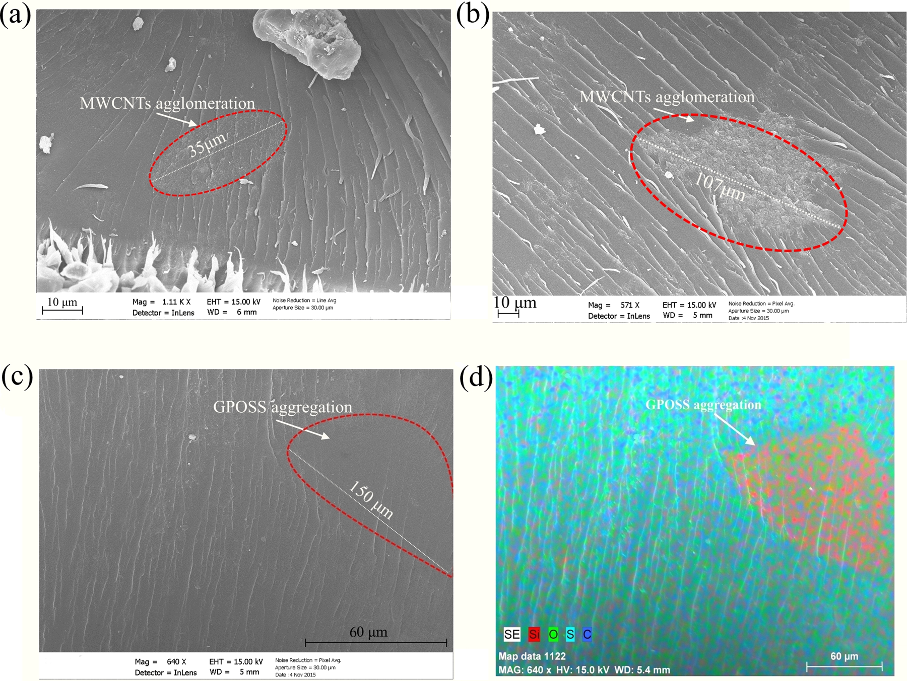
(a) SEM images of material enhanced with MWCNTs, (b) material enhanced with MWCNTs and GPOSS, (c) GPOSS aggregation, (d) EDS map data of Si, O, S and C. SEM: scanning electron microscope; MWCNTs: multiwalled carbon nanotubes; GPOSS : glycidyl polyhedral oligomeric silsesquioxanes; EDS: energy dispersive spectroscopy.
It is worth mentioning that a reduced mechanical performance has also been observed by Fina et al. 17 due to the presence of POSS aggregates. The SEM micrographs combined with EDS analysis showed solid aggregates on the fracture surface after tensile tests of the filled with Me-PSS material.
CAI tests
The results obtained from optical microscope and SEM investigation are consistent with the following results of the CAI tests. Since a larger damaged area due to the impact event is attained in the case of the filled material, a more severe material degradation as compared to the reference material is expected. A larger damaged area is associated with an increased loss of the CAI strength. A typical case for the CAI tests performed is a sudden fracture when the maximum load is reached. The fracture is developed across the specimen center line in the lateral direction.
The load–displacement curves of both reference and filled materials are shown in Figure 8. Similar curves were found in the studies by Ashrafi et al.9 and Kostopoulos et al. 10 As it can be seen in Figure 8(a), concerning the reference material, a linear load–displacement curve until the maximum load is obtained, while in the case of the filled material (Figure 8(b)), not all specimens demonstrate a linear curve and the standard deviation is larger.

Load–displacement curves for compression test of (a) reference and (b) enriched materials.
In total, the compressive residual strength was appreciably reduced (p-value = 0.005) in comparison to the reference material, based on the same statistical analysis (t-test), as described earlier. The compressive strength was 158 ± 8.5 MPa and 133 ± 19 MPa for the reference material and the filled material, respectively. Figure 9 illustrates the type of fracture of both reference and filled materials across the center line in the lateral direction; almost all specimens have fractured in a similar way. The marked areas indicate initial defects that were formed at the production stage and were revealed during the initial C-scan analysis.

CAI damage of (a) reference and (b) enriched materials. CAI: compression after impact.
Reduced strength after the impact due to the addition of nanofillers after the impact is also reported in the studies by Siegfried et al.11 and Ozugurler Ozgultekin. 12 For example, Ozugurler Ozgultenkin 12 found a reduced compressive strength of about 7%, with the addition of only 0.01–0.05% (by weight) MWCNTs into the composite materials.
The reduced residual strength in the case of the materials enhanced with MWCNTs and GPOSS can be attributed to the large increase of the damaged area as well as of the severity of damage in the form of more extensive delaminations, matrix cracks and fibre breakage after the impact test, as exhibited earlier, and also reflected in the higher DSF values obtained for these specimens (Table 2 and Figure 5). The more extended damage may be attributed to the CNT agglomerations in the matrix. 11,14,28
It should be noticed that the contribution of GPOSS in the reduction of the compressive strength remains unclear. However, a reduction of the mechanical behaviour in the case of a non-uniform dispersion has been noticed by Fina et al. 17 To separate the effects of GPOSS and MWCNT is complex and should be part of a further research.
Conclusions
The CAI performance of composite specimens enhanced with MWCNTs and flame-retardant was evaluated. For comparison, both reference and enhanced materials were used.
Apart from the damage located in the impact area, the test results obtained from C-scan analysis have shown a damage widespread out of the impact boundaries in the case of the composite material enhanced with MWCNTs and flame-retardant GPOSS. Traces of the damage out of the impact boundaries could be clearly observed under microscopy examination for the case of the filled material. The increased damage evolution has been attributed to the presence of large CNT agglomerates and the GPOSS residuals, as revealed from SEM investigation. The increase of the damage severity caused by the impact has resulted in a reduction of the order of 15% in the CAI strength value observed for the filled material in comparison to the reference one.
As a general conclusion, the multifunctionality of the material enhanced with GPOSS and MWCNTs is proved, since the electrical and the flame-resistant behaviour is improved. However, the CAI behaviour is found to be deteriorated. Hence, an optimization of both the additional compounds percentages as well as the manufacturing and mixing process is necessary, in order to achieve a multifunctional composite with comparable CAI behaviour as compared to the unfilled one.
Footnotes
Acknowledgements
The authors wish to acknowledge Professor L. Guadagno, Mrs M. Raimondo and their colleagues for their valuable input, concerning the electrical conductivity and the flame resistance investigation.
Declaration of conflicting interests
The author(s) declared no potential conflicts of interest with respect to the research, authorship, and/or publication of this article.
Funding
The author(s) disclosed receipt of the following financial support for the research, authorship, and/or publication of this article: This work was funded by the IASS project, grant agreement no. 313978 of the commission of the European Communities, European Union’s Seventh Framework Programme for research, technological development and demonstration.