
Abstract
With the rapid development of technologies based on virtual reality, image stitching is widely used in various fields such as broadcasting, games, education, and architecture. Image stitching is a method for connecting multiple images to produce a high-resolution image and a wide field of view image. It is common for most of the stitching methods to find and match the feature in the image. However, these stitching methods have the disadvantage that they cannot create a perfect 360-degree panoramic image because the depth of the projected area varies depending on the position and direction between adjacent cameras. Therefore, we propose an advanced stitching method to improve the deviation due to the difference in the depth of each area using the pixel value of the input image after the feature-based stitching. After the feature-based stitching method has been performed, the pixel values of overlapping areas in the image are calculated as an optical flow algorithm, then finely distorted, and then corrected to ensure that the image overlaps correctly. Through experiments, it was confirmed that the problem that was deviated from the feature-based stitching was solved. Besides, as a result of performance evaluation, it was proved that the proposed stitching method using an optical flow algorithm is capable of real-time and fast service.
Keywords
Introduction
With the rapid development of VR technology, there are higher continuous requirements for enhanced technologies on image stitching. 1,2 VR services are currently being provided in various fields with the emergence of 5G services, but VR does not spread as fast as expected because no killer content makes people buy VR equipment. 3 However, VR is being used for sports broadcasting and live performances through killer content in many ways. 4 To show high-resolution images such as sports broadcasting, multiple images must be accurately stitched. The performance of image stitching, the core technology of VR, is important to create seamless, 360-panorama images similar to the real world. Image stitching is a method for matching multiple images to produce a high-resolution image and a wide field of view image and it has been studied to develop various algorithms over the last few years. 4 –12,13
A technology that combines multiple images to produce high resolution and wide field of view images is commonly used in the production of special image mosaics, especially panoramic images. Stitched images are used in applications such as interactive panoramic viewing of images, architectural walk-through, multi-node movies, and other applications associated with modeling the 3D environment using images acquired from the real world. 14
For image stitching, the video signal is first captured by a VR camera module composed of multiple cameras. At this time, multiple cameras are tied to the rig to form a VR camera module, which synchronizes to start and stop shooting at the same time. These multiple image signals photographed by the plurality of cameras are combined using image stitching technology to form a specific projection format. There are various types of projection formats used in VR systems, such as Equirectangular projection (ERP), Cube-map projection (CMP), and Octahedron projection (OHP), among which ERP is most commonly used. 15
In this paper, 360-degree images are stitched using an ERP projection format. Generally, a feature-based stitching method is used to solve the association between images based on features extracted from the input image. 16 However, many studies 11,13,17,18 have so far been conducted, but no complete stitching method has been found. The existing feature-based stitching method has the disadvantage of not being able to produce a more accurate and detailed 360-panorama because the depth of the projecting area and the center point position is different between cameras according to the position and direction between adjacent cameras.
As shown in Figure 1, there are different depths between an object in a circle area and an object in a square area. However, since objects existing in 3D are projected onto a 2D image using homogeneous coordinates in the image, all are judged at the same depth. That is, the moment the change is made from 3D to 2D, depth (z-axis) information in 3D disappears. Because of this problem, if matching is performed based on the features existing in the original area, it becomes difficult to match the features existing in the square area. So, in general, to match the features of objects with various depths, an optimal transformation relationship that satisfies all is found. In the end, it is difficult to accurately match each feature, but an intermediate point where all features can be matched as much as possible is found. To solve this problem, in this paper, we propose an improved stitching method based on an optical flow algorithm that can more accurately match each feature. The suggested method calculates the overall warping information with feature-based stitching and finds overlapping areas using that warping information. To accurately stitch overlapping areas, the motion field of overlapping areas is calculated using an optical flow algorithm, and a more accurate stitching image is generated with the new warping map. Lastly, to prove the validity and efficiency of the proposed system, the experimental test was confirmed and provided the results.

Areas with different depths.
The rest of this paper is organized as follows: Related works are described in the next section. In third section, the suggested method is described, and the experimental results and analysis are described in the fourth section. Conclusion and future work are provided in the final section.
Related work
Feature-based image stitching
Feature-based stitching methods are performed in the order of Feature Extraction, Feature Matching, Model Estimation & Image Warping, and Image Blending.
When inputting multiple images, you can find features invariant in size, rotation, noise, and brightness in each image, and use their features to match the same features in different images. The matched feature set is called the Corresponding Point, and it is used to calculate the model projected into the 360-degree image. After the warping to 360-degree image using the calculated model and blending process to make the boundary of the image naturally, the 360-panorama image is completed.
Figure 2 shows the feature-based stitching process. The main steps, Feature Extraction, Feature Matching, Model Estimation & Image Warping, and Image Blending, are as follows.

Feature-based stitching process (authors’ work).
Feature extraction
The method for extraction of feature uses feature-point algorithms such as Scale Invariant Feature Transform (SIFT), Speed-Up Robust Features (SURF), Oriented BRIEF (ORB), FAST to find and classify images that have unique characteristics such as image size, rotation, and brightness. After that, the relation between the feature and the surrounding pixels is calculated to generate a descriptor for each feature that describes the feature information.
Feature matching
By comparing descriptors, we find a feature of overlapping image that most closely resembles the feature of the current image and feature matching one to one. RANSAC is used to select the matching model with the most inliers and to remove the outliers beyond this model. 13 The relationship of matching pairs between images through the matching model is stored as a homography matrix. Through this homography matrix, the rotation matrix and focal length are obtained for each image.
Model Estimation & Image Warping
Multiple images are mapped from the current image to a coordinate system such as spherical, cylindrical, planar, and annular so that multiple images lead to a single picture, and then projected and stored as a 2D plane image. In the process of warping, the method for warpings, such as the Spiritual Projection, Cylinder Projection, and Plane Projection is different depending on the purpose of 360-panorama.
Image blending
After warping, several photos are placed in one photo, but panoramic images have created that look like a distortion of the differences between the images as if they were pasted with a post-it. The seam finder is used to determine the seam with less error between the images, and blending performs a natural connection of the current line to adjacent pixel values.
Problems with feature-based stitching method
Because this feature-based stitching method is the core of the correspondence point, the stitching results are poor if there is an incorrect correspondence point. Also, since several corresponding Points are projected in two dimensions, and three-dimensional depth information is lost when creating a model, the generated models can be different according to the difference in-depth information.
To generate a model that considers all the Corresponding Points near the boundary of the image, some errors are inevitable. To minimize this problem, the RANSAC technique 13 or model optimization technique 11 was introduced, but it is still difficult to obtain a perfect 360 stitched image since these techniques also have limitations. To solve this problem, this paper proposes a stitching method using an optical flow algorithm.
Optical flow
The physical concept of describing the motion state of an object in a real three-dimensional space is called the motion field. Each point in the three-dimensional space reaches a new position after a certain operating time, and this displacement process can be described as a motion field. The signal received by the computer in the space of computer vision is represented by a two-dimensional motion field because it is two-dimensional image information.
The optical flow algorithm is based on three assumptions.
19
Brightness constancy: A pixel on any object does not change its value even if the frame changes. Time persistence: The movement in the video is not fast. In other words, the time changes progress faster than the motion of the object in the image. Space Consistency: Spatially adjacent objects are more likely to be the same object.
Optical flow is a distribution that shows how the brightness pattern has shifted in an image. Through this, information about the movement of objects can be obtained locally. Optical flow can be divided into a sparse optical flow and dense optical flow. An example of a sparse optical flow is the Lucas-Kanade method, 19 which is a method for measuring a motion vector for a feature point. Dense optical flow is a method for measuring the motion for all pixels more densely. Therefore, the computational amount of dense optical flow is more time consuming, but it has the advantage of more accurate motion measurement. In this study, the Farneback algorithm 20 that is a kind of dense optical flow is used to estimate the motion vector of the image.
Farneback algorithm
The Farneback algorithm calculates the motion field, which indicates how much pixel and area between two images have changed. The algorithm is divided into three steps: pyramid generation, polynomial expansion, and displacement, and proceed respectively as shown in Figure 2. Because the Farneback algorithm calculates the motion vector by calculating the pixel change of the image, it is possible to measure the direction of movement and distance of moving objects and pixels in the image.
The process of the Farneback algorithm is shown in Figure 3. When two images are received, the high pass of the image is removed through a low pass filter process. Then reduce the image size. As the image is reduced by one step, an image step similar to a pyramid is formed. The collection of images is called an image pyramid and uses a Gaussian pyramid, which is a form of an image pyramid using a Gaussian filter as a low pass filter.

The process of the Farneback algorithm.
The Farneback algorithm uses a method to gradually increase the accuracy of the motion field by first approximating the motion field from the top-level image of the pyramid and then recalculating it from the larger image. The motion field refers to a set of Motion Vectors, which are displacement values in pixel units, and the size of the motion field is the same as the image size.
Polynomial expansion
The polynomial expansion process refers to the conversion of the two-dimensional signal space of the orthogonal coordinate system into a basic function space. This means that a two-dimensional signal is converted into a six-dimensional signal in the basic function space (1, x, y, x2, y2, xy). As a result, one image and image area can be represented by six coefficients using quadratic equations.
 (1)
(1)
Equation 1 shows the result of approximating the coefficient using the second-order polynomial. The coefficient value of r1 to r6 can be a characteristic value representing a single pixel. However, it is impossible to calculate six unknowns with a single-pixel value, so it is calculated using neighboring pixels to generate a value representing one pixel.
Figure 4 shows the process by which the pixel value is calculated as six coefficients. Finally, if we solve the equation of Ax = b, we can find x values of six coefficients for one pixel. In this case, the variable N used is a value for designating a peripheral range based on the corresponding pixel. An area designated as N value does not apply to the calculation with the same weight but uses a method to reduce the weight of the value as it moves further away from the corresponding pixel point. This is the same as the Gaussian filter’s calculation method.
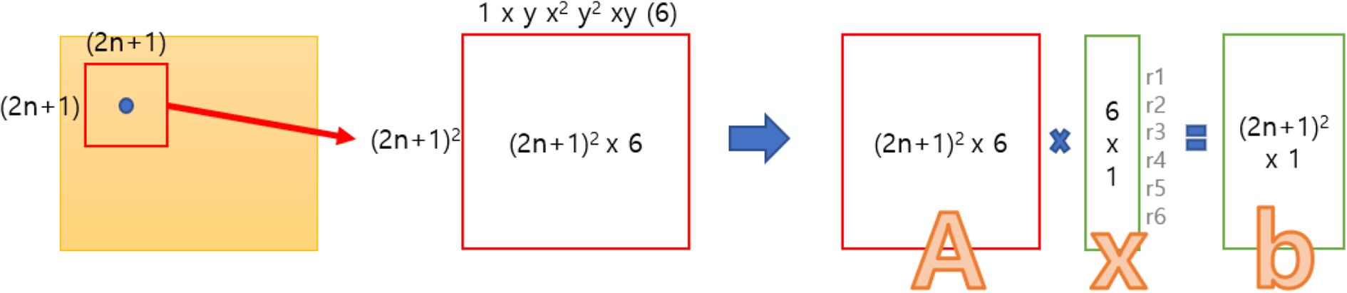
The process by which the pixel value is calculated as six coefficients.
The Farneback algorithm takes a sigma value as well as an N parameter. The sigma value determines the window size of the Gaussian filter.
Figure 5 shows the weighting value when the sigma value is 1.0. After all, N and sigma must be set to be compatible with each other. If N is set to 3, then it is most ideal to set sigma around 1.0. Generally, it is necessary to set the N value three times the sigma. If the x and y values exceed three times the sigma value, the exponential value is almost decreased to 0.011 because the area beyond this is meaningless. Thus, the calculation of the coefficient for all pixels produces one large data box with six values per pixel.

The value of the digital filter.
Displacement estimation
The process of the displacement estimation uses two data boxes obtained from the process of polynomial expansion to calculate the motion vector, which is moved in pixel units.
Figure 6 shows the process of displacement estimation, and d shows where the pixels of img1 were moved from img2. The Farneback algorithm aims to generate motion fields by calculating d values in pixels. The d value is initially set to zero. Then, as the pyramid step goes up, it uses the value of d calculated over the entire pyramid

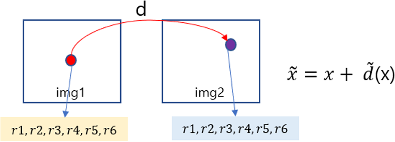
Process of displacement estimation.
The calculation method is shown in Equation 2. Using the second polynomial used in the polynomial The calculation method is shown in Equation 2. Using the second polynomial used in the polynomial expansion, the equation

Using this value,

At this time, the
After generating the optimal d (x) value, the Farneback algorithm goes through the displacement optimization process to further increase the accuracy of d value, and the calculated d value becomes the final motion vector value.
Proposed method
The existing feature-based stitching method cannot create a complete 360-panorama. This is because the depth of the projected area varies depending on the position, direction, and location of the object between adjacent cameras. Also, it is difficult to achieve accurate stitching performance because the central point positions between cameras are different. In this paper, an improved stitching method using an optical flow algorithm is proposed to solve these problems. To use the proposed stitching method, image stitching must be preceded based on the feature. So we will refer to the previous stitching as Initial stitching and the proposed method as optical flow stitching. Initial stitching is a specific requirement for warping input images as a pre-work for using the suggested optical flow stitching. In the initial stitching stage, the full-frame fisheye image is collated with Equirectangular to generate a panorama image. Each camera parameter is calculated and the area overlaps with the warping image can be calculated using the value.
The overall flow of the proposed algorithm is shown in Table 1 and the part of optical flow stitching consists of steps 3, 4, 5, and 6 of Table 1.
The overall flow of the proposed algorithm.

In Initial stitching, when multiple images are input, project them with equirectangular to stitch them to 360 images. Figure 7 shows an image of the result, which is projected as equirectangular.

The process of the equirectangular projection (authors’ work).
Image stitching is performed using an image projected by equirectangular. Figure 8 shows the stitching results of the equirectangular images and creates a single panorama image.

Feature-based image stitching (authors’ work).
After the Initial stitching process, the overlapping area between each image camera parameter and image can be calculated. The proposed optical flow stitching algorithm consists of 4 modules, and each module corresponds to 3, 4, 5, 6 in Table 1. In this paper, we describe in detail the calculation of overlapping area, the calculation of motion field, interpolation of motion field, and generation and application of motion field map.
Calculation of overlapping area
The 360-panorama image generated by Initial stitching(feature-based image stitching) does not exactly stitch all areas as shown in Figure 9. In particular, problems arise when new objects appear in overlapping areas, or when there are no edges or features. Thus, the problem area is limited to the overlapping area, it can be the 360-panorama images, which is similar to reality as long as the overlapping areas of the problem are exactly stitched.

Feature-based image stitching (authors’ work).
Overlapping areas use the information calculated in Initial stitching. Besides, through Initial stitching, the ERP (Equirectangular Projection) transformation relationship of each image and the mask information of the stitched image can be obtained.
Each image mask information can be obtained from the ERP area through the stitched information shown in Figure 10. We can find a seam line using mask information. It can be obtained by performing a bit operation (and) on the mask image as shown in Figure 11. The reason for using the seam line without overlapping areas for each image is because the area that is distorted is centered on the seam line. If the seam lines are correctly stitched, the entire panorama image will be similar to the real world. Also, using overlapping areas requires a lot of processing time, and there is a risk that the image itself may be unnatural if a wide range is distorted. Therefore, we gradually expand the seam line to find the area to calculate the motion field.

Stitched mask image (authors’ work).

Seam area calculation process using a mask (authors’ work).
As shown in Figure 11, when calculating the seam line using the mask information, a narrow area is selected.
It is possible to increase the size of the seam line by performing a dilate filter operation on the existing mask image to widen the range on the seam line. The dilate operation is a method for converting to the highest value inside the filter and is generally called an expansion operation.
Figure 12 shows the result of the dilate operation. The overlapped area can be adjusted by the filter size of dilating. In this paper, a large filter is used to widen the overlapped area.

Result of dilating application to mask image (authors’ work).
Figure 13 shows the result of calculating the seam line using the dilate operation. It can be seen that the seam line is thicker than before the dilate operation. The thickened seam line is used as a mask of the overlapping area and applied to each image converted into actual ERP.
Calculation results of the seam line.
Figure 14 shows the result of calculating the image of the overlapping area by applying the thickened seam line mask to the ERP converted image. The seam line has greatly expanded to a large area so that it can contain an empty image. The inclusion of an empty image is not a problem because the black area in the motion field calculation does not affect the moving value of the actual image pixel value.

Results of inserting images into the same area (authors’ work).
In this paper, the problem of slight misalignment could be solved by adjusting the filter size on lines where the black area is generally invisible, although the range of human movement was rather wide.
Calculation of the motion field
The motion vector is commonly used in image recognition as a vector (direction and size) value for the changed motion in the image. Usually, when calculating motion displacement between successive images and the value of the motion vector is calculated using the optical flow algorithm.
In this study, the motion vector is calculated using the overlapping areas of each other in the static image instead of the continuous image using the characteristics of the optical flow.
By using the calculated motion vector, a motion field can be created and warp the overlapping areas with the values to fit the discrepancy. Correct alignment assumes that the motion vector value is correct. Therefore, if the motion vector value is not correct, the stitching may be unnatural or mismatched.
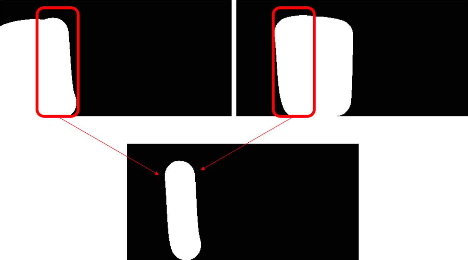
Figure 15 shows the results of applying images of overlapping areas to the Farneback algorithm. The application results indicate how far the values in each area have moved. In this paper, the motion vector, which varies from the left image to the right image of the overlapping area, was calculated and the motion field was created by obtaining the value of the motion vector for each area. In this study, since the distortion can be severe when only one side is changed, the motion field is calculated in both directions and the half-way is selected.

Results of motion field calculation in overlapping areas (authors’ work).
Figure 16 shows how to calculate the bidirectional motion field. This approach can mitigate the skew of one image and result in more natural stitching results. Motion fields obtained through the Optical Flow algorithm exist in pixel units, and if all pixel values move a certain amount, it is possible to know whether they are in the same position. Get these motion fields in both directions and move them in half to match each other. If they do not match, it is determined by the average value. This process improves the accuracy of motion fields calculated in only one direction.

The application method of motion field (authors’ work).
Connection of motion field
The calculated motion field represents the seam mask area, and if the area is warped through the motion field, the areas connected to the seam mask will be unnatural. It is because only the pixel values of the seam mask area are changed by applying the motion field value, and the rest of the area is the original. In the end, it is needed to connect the seam mask areas and boundaries of other areas naturally.
Figure 17 shows the boundaries of overlapping and other areas. In this paper, padding is used to seam mask areas to connect the areas naturally, and the padding areas are interpolated and connected naturally.

Boundaries of overlapping and other areas (authors’ work).
Creating and applying the warping map
A warping map was created to apply the motion field that completed the interpolation work of seam mask areas to 360-panorama. The warping map puts the transformation information of the overlapping regions. When applying the values of the motion field for seam mask areas to the warping map, there is a blank in the result after each value moves. If there is a space, fill it with the interpolation value reflecting the values of up, down, left, and right.
Experimental results and analysis
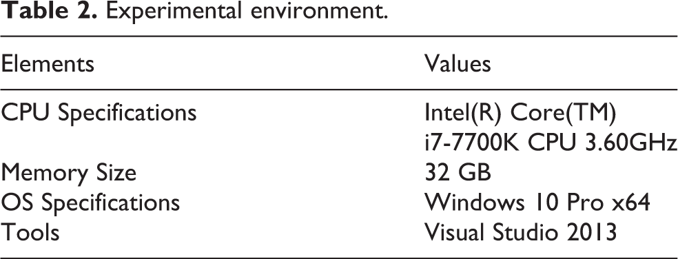
In this study, we proposed a stitching method that improves the distorted image by creating a motion field using the dense optical flow algorithm and applying it to the stitched panorama. Table 2 shows the experimental environment of proposed method.
Experimental environment.
The experiment was conducted by receiving six still images of a full-frame fisheye type from a fixed camera. At this time, the method of feature-based image stitching produces a conversion equation that projects full-frame fisheye with Equirectangular, and the coefficient value of the conversion equation is calculated. Based on the conversion equation, the optical flow stitching method is performed.
The experimental result was obtained by comparing and analyzing the performance of the feature-based stitching method 11 and the optical flow stitching method proposed in the paper. Besides, the performance of the optical flow stitching method was measured to test whether real-time fast service is possible, and as a result, its efficiency and validity were proved.
Experimental environment
Performance evaluation of the stitching method
Figure 18 shows the 360-panorama image created by the existing feature-based image stitching, and Figure 19 shows the 360-panorama image generated by the proposed optical flow image stitching.
Feature-based image stitching (existing method).

Optical flow image stitching (proposed method, authors’ work).
Comparing the two images, as shown in Figure 20, the proposed stitching technique is naturally connected to parts more displaced than the existing technique. The reason is that the pixels that have deviated from the existing stitching method are aligned with each other using motion vector values. However, not all motion vector values calculated using the optical flow algorithm are accurately stitched. Therefore, even in the proposed stitching result, the unnatural part of stitching can be confirmed. In the end, if the accuracy of the optical flow algorithm is improved, more improved stitching performance can be expected.

Feature-based image stitching vs optical flow image stitching.
Figure 21 shows the comparison results before and after the interpolation process performing the fifth step of the proposed algorithm module. Without interpolation, the phenomenon of being out of line can be seen because the outer area remains intact when overlapping areas are moved slightly. However, if you naturally interpolate the area overlapping with the outer area, you can see the change naturally as shown in the upper left result of Figure 21.

Comparison results before and after the interpolation process (authors’ work).
As a result of confirming the stitching performance, the feature-based stitching method showed a shift between the moving object and objects with different depths, but it was confirmed that the problem was solved or alleviated when the optical flow stitching method was additionally applied. The more accurate the motion field value, the higher the accuracy, and the physically incompatible image can be solved through distortion.
Measuring the result of processing time
The initial stitching process results in a 360-Panorama image, which is the result of concatenating each warped image. The size of the output image can be changed freely and will be affected later when using Optical flow stitching. The larger the output image of Initial stitching, the larger the amount of image information is. Therefore, better results can be obtained. As a result, lowering the resolution of the output image has a problem of lowering the accuracy performance. Therefore, the tradeoff between speed and accuracy should be carefully considered.
Figure 22 shows the results of measuring 10 processing times and stitching time using the entire optical flow. The resolution of the output image is a 3840 × 1920. If the entire image is six, there are 10 overlapping areas. When we proceed with the proposed stitching with a 3840 × 1920 resolution, it takes about 700 ms to process the stitched area. Besides, the interpolation time is the longest among the processing modules, and if the interpolation is further improved, it will be possible to stitch at faster processing speeds.

Measuring the result of processing time.
The proposed method proceeds the same process for each overlapping area. If these tasks are conducted pervasively, they can operate at optimized throughput. Figure 23 shows the result of comparing the processing speed of Single-Core and Multi-Core, and it shows different performances depending on the resolution of the output image, respectively. As a result, the production of a warping map is processed in parallel, but the processing speed is not different. It is because each motion field map is assigned to a buffer called a Warping Map. By viewing the total value, the performance is improved approximately twice as much as the Single-Core when using Multi-Core. Besides, the matching module has been found to have more than three times the performance effect.

Measuring the result of processing time (single and multi-core time).
Conclusion
The goal of image stitching is to create natural-looking images free of artifacts that may occur due to the relative camera motion 21 and the research of video stitching 22 is currently being conducted in a variety of ways. In this paper, we proposed an improved method of image stitching based on the optical flow algorithm to solve the problem of feature-based image stitching.
In the case of feature-based image stitching, it is difficult to stitch all regions accurately considering all other areas in different depths because feature samples are extracted from the population and the transformation relationship is calculated. To solve this problem, we proposed a method for calculating the conversion relationship for each pixel value. As a result, it was possible to solve or alleviate the problems of the feature-based stitching method, and to create a foundation for further performance improvement in the future.
This paper introduced a stitching technique that uses still images as a reference, and it was possible to improve the lack of stitching problems due to the object depth of the still image or the error in calculating the conversion relationship between the images. The proposed optical flow algorithm is a technique widely used for feature tracking and influences predicting the movement of specific objects or features in a continuous image. Therefore, it can be used more effectively in a place where stitching the real-time images that are filmed continuously.
For example, if it is necessary to continuously stitch panorama images, after using feature-based stitching once and then continue to use the proposed stitching technique to track and stitch the moving objects and features effectively. The continuous image stitching requires additional optimization tasks, and the improvement of speed-up and stitching performance will be required to achieve real-time stitching. Besides, techniques that attempt to stitch with a focus on moving objects should be studied in the future.
The proposed algorithm is a technique that can be used for real-time stitching, and it can be used a lot for the video stitching technique. Therefore, the algorithm proposed in this paper can be applied to the following fields. First, it can be used in the control system. When a surveillance environment such as CCTV is required, monitoring all areas at once is more effective than monitoring with one camera. Secondly, it can be used as a relay service. Real-time panorama can be used for sports and tourism services. Thirdly, it can be used in robots for disaster and guidance.
In order to apply 360-degree panorama to such various fields, it is necessary to provide a realistic image without shifting the boundary area of the stitching. This is because new content can be added on top of a 360-degree panoramic image or applied to various applications only when a high-quality image is received as an input. For example, if additional services such as object detection and object recognition of video are supported, the quality of the service is degraded unless the video is of high quality. However, in the case of the existing stitching technique, when a new object appears in the boundary area, there is a high possibility of deviation due to the depth problem. Since the technique proposed in this paper solves the depth problem when a new object appears in the boundary area, a more natural image can be supported to the application. Eventually, by providing higher quality input data to disaster and guidance robots and surveillance systems, new functions can be serviced more stably by incorporating AI technology.
In this paper, an experimental evaluation that quantitatively measures the accuracy of stitching was not performed. The reason is that feature matching or model estimation is not performed in the proposed stitching method, and it is difficult to use the motion vector value that plays a role as an index to determine the accuracy of stitching. Finally, we replaced the experimental results solved through the image stitching method, which suggests sample data that is a problem in the feature-based image stitching method. For future work, a quantitative experimental method of image stitching is required.
Footnotes
Data availability
The data used to support the findings of this study are available from the corresponding author upon request.
Declaration of conflicting interests
The author(s) declared no potential conflicts of interest with respect to the research, authorship, and/or publication of this article.
Funding
The author(s) received no financial support for the research, authorship, and/or publication of this article.