
Abstract
A multi-camera network is proposed to estimate an aircraft’s motion parameters relative to the reference platform in large outdoor fields. Multiple cameras are arranged to cover the aircraft’s large-scale motion spaces by field stitching. A camera calibration method using dynamic control points created by a multirotor unmanned aerial vehicle is presented under the conditions that the field of view of the cameras is void. The relative deformation of the camera network caused by external environmental factors is measured and compensated using a combination of cameras and laser rangefinders. A series of field experiments have been carried out using a fixed-wing aircraft without artificial makers, and its accuracy is evaluated using an onboard Differential Global Positioning System. The experimental results show that the multi-camera network is precise, robust, and highly dynamic and can improve the aircraft’s landing accuracy.
Introduction
Estimating an aircraft’s motion parameters is an important application of multi-camera networks, 1 such as vision-based aircraft landing. 2,3 It is a basic requirement of flight tests to measure the aircraft’s distance, azimuth, velocity, and pose relative to the reference platform on which it will land, so that the aircraft can land universally and dynamically with high precision, even when the platform is moving. 4,5
There are a number of motion parameter measurement systems for aircrafts currently in service. GPS can provide an accurate aircraft position, velocity, and pose estimate with an onboard hardware, and they are incapable of determining distance, azimuth, velocity, and pose estimates relative to a moving reference platform without additional ground infrastructure. 6 The GPS is not reliable in certain conditions, such as under electronic jamming, near trees, or near tall buildings. 7 In addition, GPS have been ruled out in certain applications, for example, some platforms like warships cannot send their position to the aircraft for fear of jeopardizing their security. 4 Therefore, this consideration places emphasis on passive sensors.
The passive sensors, such as radar and microphone arrays, have been widely applied for motion parameter estimation of aircrafts. Thales Company in France has developed a series of advanced radar systems that meet a wide range of needs for surveillance, like SMART-L, or VARIANT. Due to its larger power budget, SMART-L is dedicated for the early detection and tracking of small aircraft in very long-range performance. 8 VARIANT is a multipurpose, short-/medium-range 2-D radar for air and surface surveillance. Its principal role is automatic target detection and tracking for both aircraft and surface targets. 9 Meanwhile, Thales has developed an advanced calibration system for radar system, those calibration systems perform well even under heavy weather condition, to satisfy the requirements of weapon systems. However, the radar is quite expensive, for example, the cost of SMART-L radar is around 12 million dollars. The arrays of microphones can also be used for detecting and tracking aircrafts as an alternative for radars. The main advantages of microphone arrays in comparison with radar systems are comparatively the lower cost, and it is electromagnetic and pollution free. 10 The radar and microphone array systems are particularly noted for their excellent all-weather and automatic aircraft detection and track capabilities at long distance. Nevertheless, these systems are highly sophisticated and expensive. Moreover, since the motion parameters of aircraft in flight tests are expected to measure relative to a reference platform in the range of 20–1000 m only under normal weather conditions, other measurement systems that are inexpensive, simple, and reliable are highly desired.
Compared to other measuring means, such as GPS, radar, or microphone arrays, a multi-camera network has distinct advantages regarding the complicacy of the facilities and the expense of the costs. 11,12 Therefore, multi-camera networks serve as an effective way to estimate an aircraft’s motion parameters. Measuring volume and accuracy are important performance characteristics of vision systems. Both are dependent on the field of view (FOV) and resolution of the cameras. 13 With the high-speed and long motion range capabilities in aircraft landing, 4 the FOV of cameras should cover the aircraft’s motion spaces (20–1000 m), and the motion parameter measurements of the aircraft have the requirement of measuring volume and accuracy at the same time, that is, the large FOV and high spatial resolution, respectively. It is almost impossible for conventional binocular vision to perform this large field measurement tasks with an acceptable degree of continuity or reasonable accuracy. To cope with this problem, using multiple cameras by arranging them as a sensor network to observe the whole motion and measure the whole range has an important application value. 14,15
To calibrate the cameras’ parameters precisely is the core of motion parameter estimation of an aircraft. Because the cameras often need to adjust the depth of field and installation angle, etc., according to the actual measurement task, calibrating the camera parameters in the laboratory in advance is not suitable. 16 It is necessary to calibrate the camera parameters directly in the field, even if the FOV of the camera is void. For example, cameras that are pointing to sky cannot find any calibration objects in the FOV. In addition, the reference platforms where the cameras are installed are subject to elastic deformation, due to the external environmental factors in field experiments, such as high wind, 17 subsidence, 18 and deformation of installed towers. 19 The inevitable deformation will affect the measurement accuracy. 20 For example, as the baseline distance of two cameras is about 70 m, 1 arc minute of angle deformation and 1 mm of displacement deformation between the left and the right camera coordinate system would result in at least 6 m of positioning error in the measuring distance of 1000 m. Therefore, the relative deformation between cameras is a crucial error source for measuring data from a multi-camera network, since an accurate measurement and compensation of relative deformation in real time are of great significance.
In order to obtain the motion parameters of an aircraft, we have built a multi-camera network whose FOV is combined by multiple groups of cameras and developed a method to compensate the relative deformation. The proposed multi-camera network has been tested when a fixed-wing aircraft is landing in large outdoor fields, and the results of the tests are shown in this article. The rest of this article is organized as follows: the second section presents the architecture of our multi-camera network; the third section describes the correlative algorithms in the multi-camera network, including camera calibration, relative deformation measurement, and motion parameter measurements. Experimental results and discussions are given in the fourth section, followed by a brief conclusion in the last section.
Architecture of our multi-camera network
Figure 1 shows a multi-camera network that is designed to measure the aircraft’s motion parameters relative to a reference platform in the range of 20–1000 m. The multi-camera network is composed of two sets of measurement units that are installed on the left side and the right side of the reference platform, respectively. Each measurement unit mainly consists of three parts.

Architecture of our multi-camera network.
(1) Three high-speed cameras (C1, C3, C5 and C2, C4, C6). These cameras are used to measure far-field (500–1000 m), middle-field (100–500 m), and near-field (20–100 m), respectively. The pixel resolution of the cameras is 1280 × 1024 pixels at 50 frames per second (fps), and the pixel patch is 14 × 14 μm. The corresponding focal lengths of the camera lens are 80 mm with the FOV 12.78° × 10.24°, 50 mm with the FOV
(2) Relative deformation measurement equipment (C7, LRF1 and C8, LRF2), including a high-speed camera and a laser rangefinder (LRF). C7 and C8 are set to see each other for measuring the platform’s relative deformation between the left side and the right side. The pixel resolution of the cameras is 1024 × 1024 at 50 fps, and the pixel patch is 2.45 × 2.45 μm. The focal length of the camera lens is 100 mm with the FOV
(3) Other equipment, such as an image transmission and storage system, a GPS time synchronization system, and a temperature control system. All the high-speed cameras and the LRFs will receive a common synchronized time stamp provided by the GPS time synchronization system during the measurement process.
To elaborate the measuring principles of our multi-camera network in this article, some symbols are introduced as follows. Platform coordinate system Calibration coordinate system Body coordinate system Parameters of camera Ci:
The workflow of our multi-camera network roughly divides into three phases: (1) Calibrate the camera parameters (
Principle of the multi-camera network
Camera calibration
Measuring the motion parameters of the aircraft requires a previous calibration of the multi-camera network in order to find the intrinsic parameters
The position of the UAV is measured by the designed positioning measurement system, which is composed of an azimuth camera CA, a wide-beam LRF, and a GPS synchronization controller, as shown in Figure 2(a). In order to cover a wide area for measuring the UAV’s position, the pose of the azimuth camera is usually adjusted to the state of a large pitch angle, so the projections of the control points which are close to the ground platform are in the lower half of the image, and the control points and the azimuth camera are approximately coplanar. In this condition, Shang et al.’s method
16
is adopted to calibrate the parameters of the azimuth camera, including the intrinsic parameters
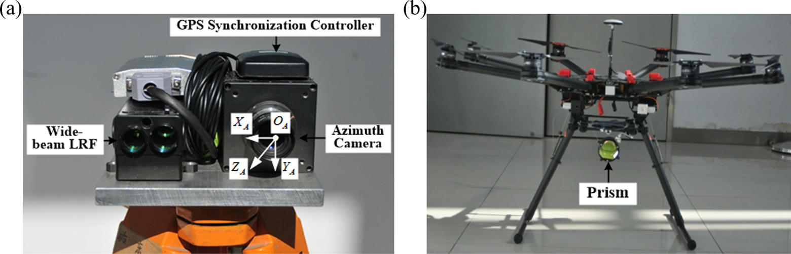
Constitute of the positioning measurement system. (a) The positioning measurement system for a UAV. (b) Multirotor UAV and prism. UAV: unmanned aerial vehicle.
A multirotor UAV and a prism are shown in Figure 2(b). The multirotor UAV can make a flexible motion, and the prism is mounted underneath the UAV, which is used to reflect the laser light. The azimuth camera and wide-beam LRF controlled by the GPS synchronization controller are used to obtain the azimuth

According to the extrinsic parameters

Figure 3 shows the idea of the proposed calibration method for the cameras, for which the FOV is void. The method roughly divides into two steps. First, the cameras

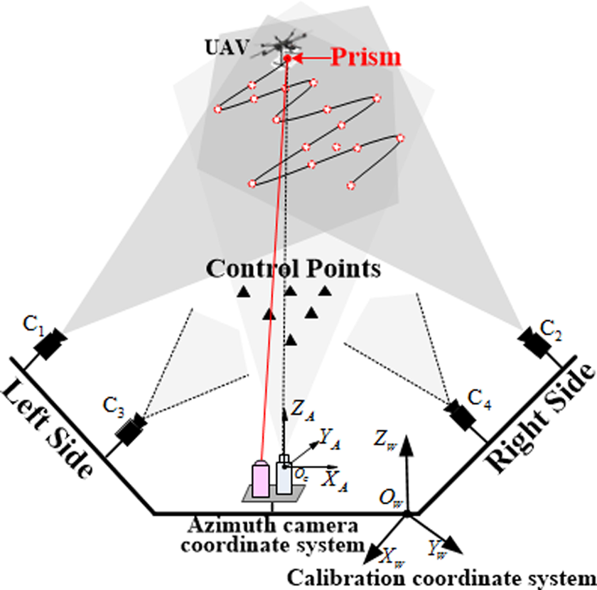
Schematic diagram of the proposed camera calibration method.
where
Thus, the intrinsic parameters
Relative deformation measurement
The principle of relative deformation measurement is shown in Figure 4. Cameras C7 and C8 combined with LRF1 and LRF2 are used to measure the relative deformation between the measurement unit in the left side and the other one in the right side. Each measurement unit is fixedly connected with the corresponding control points, and these control points are set to be seen by the camera across form themselves. Since the platform coordinate system is built on the camera coordinate system of camera C1 on the left side of the platform, it is assumed that the measurement unit on the left side remains stationary, and the measurement unit on the right side occurs deformation relative to the platform coordinate system.

Schematic of our relative deformation measurement method.
Using the extrinsic parameters H7, H8 of cameras C7, C8 calculated in the previous camera calibration, the coordinates of the control points that are fixedly connected with the measurement unit can be expressed in the corresponding camera coordinate system


where n7 and n8 are the number of the control points captured by the cameras C7 and C8, respectively.

Due to the deformation, the homogeneous transformation

where
The deformation of the right measurement unit

Then, the angle deformations
Motion parameters measurement
As mentioned, the motion parameters of the aircraft are obtained in the platform coordinate system


Based on the matched feature points on the stereo vision images, the position


Experiments and results
To verify the performance of our proposed method, the multi-camera network has been set up in a large outdoor field, which is used to estimate the motion parameters of a fixed-wing aircraft during actual landing under normal weather conditions. Since there are not any other existing systems, such as radar and microphone arrays, in the reference platform, we have not compared the performance of our multi-camera network with other passive sensors. Considering the onboard Differential Global Positioning System (DGPS), which is installed in the aircraft, the comparison of the multi-camera network with an onboard DGPS is presented.
Camera calibration experiments
Due to limitations of the outdoor field, the measurement unit in the left side is installed at about 0.5 m from the ground, but the measurement unit in the right side is installed at about 10 m on specially constructed towers. The baseline distance of the two measurement units is about 70 m. The control points’ position coordinates in the calibration coordinate system are measured by a total station (Leica NTS312) first, then the cameras can be calibrated by the presented calibration method. The azimuth camera is calibrated by Shang’s method. The calibration results of azimuth camera CA in the calibration coordinate system
Calibration results of camera CA.

RMS: root mean square.
All the UAV’s positions in the calibration coordinate system

The flight trajectory of UAV captured by the camera C1. UAV: unmanned aerial vehicle.
The calibration results of the cameras C1 and C2 in the calibration coordinate system
Calibration results of cameras C1 and C2.
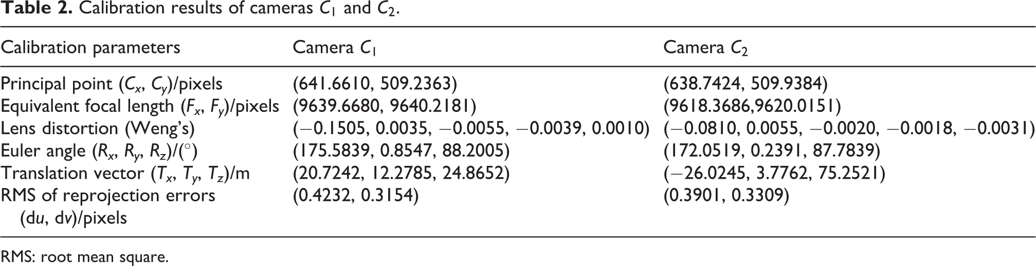
RMS: root mean square.
Motion parameter measurement experiments
The motion parameter estimation of the aircraft is divided into two steps: the relative deformation between the two measurement units caused by external environmental factors is first measured, then we compensate the deformation and calculate the motion parameters of the aircraft relative to the platform coordinate system. A series of field experiments have been conducted to evaluate the multi-camera network. The landing experiments for a fixed-wing aircraft without artificial makers are detailed in the following. The motion region of the fixed-wing aircraft to be measured ranges from 1000 m to 20 m relative to the platform coordinate system. The aircraft gradually descends from a height of 200 m with a glide-slope angle of 3.0°. The speed of the aircraft is about 30 m/s, and the time of landing is about 35 s.
The measurement results of the angle deformation

Measurement results of angle deformation.

Measurement results of displacement deformation.
In the landing experiments, it is necessary to determine the distance, azimuth, velocity, and pose of the aircraft with respect to the reference platform. The accuracy of the proposed multi-camera network is evaluated using an onboard DGPS system. Distance measurement errors of the fixed-wing aircraft between the DGPS and the multi-camera network while landing are shown in Figure 8. According to the results, the multi-camera network performs as expected with the distance error decreasing when the aircraft approaches, and the distance error is significantly decreased in the process of entering the near-field from middle-field, because the calibration accuracy of the cameras in near-field (

Distance measurement errors between the DGPS and the multi-camera network. DGPS: Differential Global Positioning System.
The measurement results of the aircraft’s azimuth, velocity, and pose relative to the platform coordinate system during the landing have been shown in Figures 9 and 10, respectively. Since the pose of the aircraft has not been measured by an onboard DGPS, the accuracy of the pose cannot be assessed, but the measurement results are quite smooth and consistent with the IMU information recorded in the aircraft. The results of our experiments show that the multi-camera network can be used to obtain the motion parameters of the aircraft over a large range with a fairly high accuracy.

The azimuth and velocity of the aircraft relative to the platform coordinate system.

The pose of the aircraft relative to the platform coordinate system.
Error analysis and discussion
Although promising results have been obtained under normal weather conditions, there are some factors that could influence the measurement accuracy of the proposed multi-camera network. The main factors are divided into three parts: camera calibration accuracy, relative deformation measurement accuracy, and environmental factors.
The accuracy of camera calibration is mainly influenced by the measurement accuracy of the control points. According to the view field of the cameras, the coordinates of the control points are measured by a total station and the designed positioning measurement system, respectively. The main factors that could influence the designed positioning measurement system are the installation distance between the wide-beam LRF and the azimuth camera, the ranging error of wide-beam LRF, and the calibration error of the azimuth camera. Considering that the distance between the UAV and the azimuth camera is much greater than the installation distance between the wide-beam LRF and the azimuth camera, the installation distance is negligible. The ranging error of the wide-beam LRF is 0.25 m. The azimuth camera CA is calibrated by Shang’s method using the control points measured by total station. Compared with the accuracy of the total station, the accuracy of the control points measured by the designed positioning measurement system is lower. Therefore, the calibration accuracy of cameras in middle-field and far-field (
The accuracy of relative deformation measurement is mainly influenced by the installation error between the LRF and the camera, the ranging error of LRF, and the calibration accuracy of the cameras
Due to the visible light camera, the performance of the proposed multi-camera network is inevitability influenced by environmental restrictions, such as fog, heavy storms, temperature, air turbulence, and ambient lighting. 27 These factors are all we need to solve or reduce the impact. For temperature variations, we have installed the temperature control system which ensures that the cameras operate under relatively constant temperatures. The temperature control system is helpful for reducing the influence of temperature variations in outdoor fields. The performance of the proposed multi-camera network is poor, and even cannot work under heavy weather conditions, for example, fog at sea, heavy storms, or ambient lighting, because the image features of the aircraft cannot be correctly detected and tracked. In this condition, some light-emitting devices have to be installed on the aircraft in advance, which highlight the key positions of an aircraft, like nose and wings of a plane. 14 But the artificial makers will increase the load of aircraft. The proposed multi-camera network has not considered the influence of air turbulence under normal weather conditions. But the compensation of air turbulence is necessary in condition of high temperature and strong wind in large outdoor fields. The implementation of air turbulence compensation methods is the focus of our future research.
Conclusion
In this article, a multi-camera network is proposed for measuring an aircraft’s motion parameters relative to a reference platform. A calibration method for the camera for which the FOV is void is presented, by using the dynamic control points created by a multirotor UAV, and the cameras combined with LRFs are adopted to measure the relative deformation between the measurement unit on the left side and the other one on the right side. To verify the proposed multi-camera network, its performance has been tested when a fixed-wing aircraft without artificial makers is landing in a large outdoor field, and its accuracy is evaluated using an onboard DGPS system. The experimental results show that the multi-camera network is precise, robust, and highly dynamic under normal weather conditions. Compared to a current setup for measurement systems like radar and GPS, it can meet the requirements of accuracy, but has the character of measuring large sets of points and has no special requirements on the structure of the aircraft. We can get the conclusion that the proposed multi-camera network can effectively establish a new type of measurement means for an aircraft without artificial markers. It can implement the accurate landing of an aircraft without increasing its load. Certainly, for the cases that the aircrafts are taking off or are launching from the reference platform, the proposed multi-camera network can also be used to measure the aircraft’s motion parameters without modifications in the range of 20–1000 m, as long as the aircraft appears in the FOV of the multi-camera network.
Our future work will focus on the implementation of other calibration means, such as launching fireworks arrows, or emitting visible lasers into the air. Furthermore, the implementation of air turbulence compensation methods in large outdoor fields is also the focus of our research.
Footnotes
Declaration of conflicting interests
The author(s) declared no potential conflicts of interest with respect to the research, authorship, and/or publication of this article.
Funding
The author(s) disclosed receipt of the following financial support for the research, authorship, and/or publication of this article: The research was supported by the National Natural Science Foundation of China (No.11172323 and No.51509251) and National Key Scientific Instrument and Equipment Development Project (No.2013YQ140517).