
Abstract
This work presents the development of a novel, articulated small uncrewed aerial system (sUAS) tail with coupled twist-pitch motion via a ball-and-socket joint. The ball-and-socket joint is controlled by a five-bar linkage which allows two servos to work together in twist-pitch motion, as opposed to dedicated traditional elevator and rudder servo control. The articulated tail is constructed of synthetic feathers which slide over one another via a splay degree of freedom controlled by a third servo. Additive manufacturing is leveraged in the construction of all parts of a wind tunnel model with continuous carbon fiber (CCF) reinforcement, which increased the structural stiffness from 1–2 GPa for Nylon to 15–20 GPa with CCF reinforcement. Wind tunnel test results are presented for 5 and 7 m/s wind speed with body angles of-5° to 45° angle of attack and twist-pitch articulation of −30° to 45° and −45° to 45° respectively. This articulated tail design was capable of enabling fine five axis control (e.g., no roll moment control) via pitch and twist morphing across a broad range of angles of attack and airspeeds.
Introduction
Small uncrewed aerial systems are typically one of two morphologies: a quad/multi-rotor or traditional fixed wing. The control modalities of quadrotors allow them to fly low to the ground through clutter, land easily in limited spaces, and interact with the world at relatively short range and endurance.1,2 Increasing the range of quadcopters generally results in adding lifting surfaces, like tail-sitter-style aircraft which take off vertically before transitioning to horizontal winged flight. These vehicles emphasize retaining the highly precise mode of flight related to hovering and improve overall flight range. 3
Structural adaptation research on small uncrewed air systems (sUAS) generally focuses on optimizing the vehicle for various mission segments. These typically don’t consider maneuver or precision but typically modify wing sweep, camber, twist, or span to alter control forces and moments.4–10 The most common biological morphing modalities of the wing (sweep, span, dihedral, twist, and camber) and tail (pitch, splay, and twist) contribute to unique avian maneuvers and efficiency.11–16 Birds can effectively complete aerobatic maneuvers due to their morphological changes that actively control aerodynamic forces and moments and manipulate stability.11,12,17 These morphological changes allow for flight trajectories at traditionally difficult vehicle poses, like very high angle of attack perching maneuvers.18,19 KleinHeerenbrink et al. documented the ability of birds to learn a perch trajectory that minimizes the distance over which they are at these high angles of attack, delaying the most non-linear aerodynamic events until they are as close to the perch as possible. During this short-lived, high angle of attack maneuver the system has very high transient control authority 19 during which careful pose control leads to a successful perch.
Engineering approaches to copy the perch trajectory have used wing sweep control20–22 or ornithopter designs, which approach a perch more directly and don’t leverage the swooping trajectory observed in nature. 23 Using wing sweep angle for control allows the vehicle to pitch up in a “flare” maneuver, quickly gaining lift and then reducing it by sweeping the wings along the fuselage quickly. However, the lack of control authority at high angles of attack limits the ability of that system to alter its trajectory significantly once the perch maneuver is started. Quad-copter designs can hover to approach a perch from more directions, such as directly above or below at very slow speeds.24,25 A successful perching maneuver depends on the ability to update agent pose and trajectory temporally as it moves through an approach, contact, then anchoring/balancing through rigorous control and visual information.
Recent publications have sought to utilize structural morphology observed in biological systems 26 by constructing an articulated wing and tail27–29 with inspiration from a pigeon 29 or goshawk. 27 Matloff et al. 29 notes that the prime structural-actuation considerations are twofold: (1) feathers are connected together with ligament-like elastic connections such that the lifting surface is underactuated and can be controlled by one servo and (2) feathers are connected together via a hook and barb structure that allows the lifting surface to act in aggregate instead of as individual feathers. The construction in 27 uses this idea by manufacturing feathers primarily of laser cut glass fiber reinforced composite, using only the aerodynamics loads to hold the feather together, while 29 used real feathers to leverage the hook and barb structure to lock them together. The spine-tail construction in 27 used a carbon fiber reinforced composite spine, onto which three servos are mounted for tail control: elevator, rudder, and feather splay. The elevator and rudder control are actuated through a universal joint via horizontal and vertical tail structure. In flight, the vehicle 27 is capable of increased flight performance in maneuvers like rapid pull-ups and sharp turns. 28 Other research has added a third tail control servo for empennage rotation 30 or twist via warping of the tail structure with macro fiber composites. 31
In this work a new tail structure, which was comprised of synthetic feathers that were scaled for wind tunnel testing, was generated approximating the shape of a goshawk, similar to. 27 Individual feathers were connected with elastic ligament-like material for uniform splay of the tail. This research paper hypothesizes that lateral control can be achieved by replacing the traditional elevator-rudder control structure with a ball-and-socket design that can provide twist-pitch control, without vertical tail structure and the same number of servo actuators. The objective of this manuscript is to experimentally assess the aeromechanical characteristics of the ball-and-socket design capturing deformations and forces/moments associated with longitudinal and lateral control at high angle of attack.
Model fabrication and development
Materials
Parts were printed with a Markforged X7 3D printer making primary use of Onyx material (short carbon fiber filled Nylon) with continuous carbon fiber (CCF) reinforcement where possible. The CCF is not 100% carbon fiber, but is instead a tow of fibers embedded within a nylon sheath. CCF was limited to reinforcing the build plate plane, placing a tow when the available dimension was a discrete integer of the CCF width (1 mm, 125 microns in thickness). Individual paths of Onyx filament were approximately 400 microns wide and 125 microns in thickness. Non-discrete integer dimensions, such as tapers, result in terminated paths of material, void content, and poor geometry. “Roof and floor” layers are used to finish and consolidate the outside of the part and are not available for CCF reinforcement.
Synthetic feathers were printed at a thickness of 1.125 mm (9 total layers) leading to 7 CCF reinforced layers (minus 1 roof and 1 floor layer). Wall layers of Onyx were removed to increase available CCF volume for greater stiffness albeit rougher outer geometric tolerance. We included CCF reinforcement to increase the stiffness of Onyx from 1–2 GPa (strongly dependent on humidity and temperature) to 6–20 GPa.32–34 CCF was placed in concentric rings with a continuous in-plane filament pathing calculated by the slicing software, eiger.io. Because the CCF filament has a discrete width, local CCF content differs when in-plane part dimensions are not evenly divisible by 1 mm or in cases where eiger.io must create a continuous returning path at 2 mm width. For example, the “outer” area contains three adjacent CCF filament paths, whereas the “center” area contains only one, leading to differing local CCF area fractions of 41% and 27% for “outer” and “center” areas, respectively (Figure 1).

Synthetic feather diagram of CCF reinforcement pathing in feather geometry noting “center” and “outer” designations. The color blue denotes CCF paths of material while gray denotes Onyx paths of material. Three-point bending stress-strain response for material sectioned from the “center” and “outer” show markedly higher stiffness of 14.7 and 19.9 GPa respectively.
Three point bend samples were taken from the “outer” (41% Vf) and “center” (27% Vf) parts of the synthetic feather for measurements of stiffness and strength. Compared to Onyx (2.09 GPa, 50 MPa) the center and outer member of the synthetic feather had a stiffness and strength of 14.74 GPa (Coefficient of Variation Cv = 5.8%) and 210 MPa (4.98%) & 19.90 GPa (4.94%) and 308 MPa (12.7%) respectively. The center “rachis” of biological feathers have an elastic modulus of 4–7 GPa as measured in 35 where glass fiber reinforced composite is roughly 40–70 GPa depending on fiber content. 27
Model components
The model was constructed with three primary components (1) a five-bar linkage assembly, (2) spine, and (3) a tail assembly. The five-bar linkage assembly controlled the tail twist-pitch via the angular position of the two degree of freedom five-bar with two servos (Figure 2). The short length linkage (“servolink” in Figure 2) was 27 mm in length glued to the servo horn while the longer links are 89 mm in length (“tail link A or B” in Figure 2). Linkages were printed at 3 mm thickness assembled using a press-fit mechanism undersized by 200 microns. The effector end of the five-bar linkage housed a ball-and-socket which was rigidly linked by a 2 mm diameter carbon fiber pin to the tail assembly ball-and-socket, coupling cartesian motion of the effector to twist-pitch of the tail (Figure 2). The spine was designed with a persistent minimum dimension of 9 by 6 mm in width and thickness with mounting positions for the three servos, two for twist-pitch tail motions and one for splaying the synthetic feathers. A centerline 45° diamond shaped channel (2.83 mm on a side square) was cut through the center of the spine for the splay servo to pull on fishing line which was connected to the outermost synthetic feathers of the tail.

(a) Five bar assembly pictured upside down to wind tunnel orientation, that is the five bar linkage is mounted to the underside of the model. (b) The model spine with a persistent minimum dimension of 9 by 6 mm in width and thickness with mounting points for three servos and a central load cell.
The tail assembly is comprised of 9 synthetic feathers of total length 195 mm (∼165 mm excluding the “stem”) (Figure 3). The central feather labeled T1 (Figure 3) is fixed in position. The adjoining feather TR2 (right) is layered underneath T1 continuing with TR3, TR3, and finally TR5 for the right hand side and so on for the left. Feathers have a handedness associated with a physical break that limits tucked compactness allowing the introduction of pre-stress. Each feather was covered with Ultracote thin shrink film and set into a pinned boundary condition in the tail assembly by a 2 mm plastic pin. The plastic pin was set into a draft dimension hole of 2.3 mm which post printed was ∼1.9 mm reamed by a #48 drill bit (1.93 mm) for a press fit at a fixed z-position in the assembly. The ligament connection between feathers utilized two 8 mm diameter orthodontic bands with force-displacement characteristics shown in Figure A3. In the “tucked” configuration the 12 mm long “tail ligament” was stretched to 14 mm, for a pre-load which was approximately 1 N with a maximum splay actuation force of approximately 2 N when stretched to 19 mm.

Tail assembly in a 12.8° (0.0247 m2) tucked configuration or a 32° (0.0387 m2) splayed configuration. Synthetic feathers were attached to the tail mount by a 2 mm ABS pin. (a) Tail tucked. (b) Tail splayed.
The final model total mass was measured to be 81.2 g comprised of approximately 36.9 cm3 of Onyx material and 13.5 cm3 of CCF. On a percentage basis the three KST X-08H servos (9 g each) comprised 33% of the total structural mass (Table A1). For reference the American Goshawk weighs between 655–1562 g 36 indicating that the overall weight of this synthetic tail system is reasonable when compared to actual birds.
Ball-and-Socket design and control
A ball-and-socket joint was designed for use in the articulated tail for simultaneous twist-pitch motion. A five-bar linkage was used to control the cartesian position of an end effector which was rigidly connected to the ball of the ball-and-socket (Figure 4). The two degree of freedom system was manipulated with two servos which define the angles

Five-bar linkage control of a ball-and-socket joint for simultaneous twist-pitch control. Equal magnitude and direction servo motion creates pitching while equal magnitude and opposite direction motion creates twist. Other combinations of servo motion create combined pitch and twist.
Instability in the ball-and-socket can result in situations where gravity and/or overextension can cause the ball-and-socket to move into an unrecoverable position. The likelihood of instability is inversely related to servo torque thus more powerful servos are more stable. In this work the ball-and-socket joint was stabilized with ligament-like rubber bands (similar in purpose to a biological shoulder) that were stretched across the ball-and-socket joint such that under zero loading the tail would remain level with the body (Figure 5). A single “ball-and-stocked ligament” (Figure A3) across the ball-and-socket created a preload of 2.25 N at 35 mm length each. The ligaments carry gravitational loading such that the servos are primarily tasked with articulation instead of lifting the weight of the tail. Two ligaments are placed between AB & CD and one between AD & BC, on the bottom of the model one ligament is placed between AB & CD. The ligament imbalance across the top of the joint (Figure 5) resulted in an approximate 8.4 N (2.25*2 + 2*2.25*cos(30°)) lifting force with a 6 mm moment arm.

Model top view and inset magnification of the ball-and-socket joint ligament stabilization and splay servo control.
A third servo is used to control the splay angle of the tail from approximately 13 degrees to 32 degrees for a tail area change of 0.0247 m2 to 0.0387 m2. The splay servo, located at the front of the model, pulls fishing line through the spine via pulleys in the tail to the outer most tail feathers (Figure 5). Rotation of the outermost tail feathers uniformly splays all tail feathers due to the elastic connection between each feather being under equal strain.
Wind tunnel testing
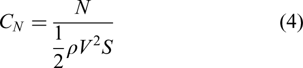
Experiments were conducted in a low speed recirculating wind tunnel with low freestream turbulence at 5 and 7 m/s. Force measurements were collected at 1 kHz for 5 s with the results presented representing the average of four data sets minus the respective tare data. Measurements were converted to forces and moments using the load cell calibration matrix and finally converted to aerodynamic forces and moments by rotating the coordinate system by the angle of attack. Aerodynamic coefficients of lift (L), drag (D), pitching moment (M), side force (N) and yaw (Y) are calculated assuming a mean chord (c) of 0.156 m with a mean span (b) of 0.145 m tucked and 0.190 m splay by equations 1–5 where S and ρ are the surface area and air density (1.2 kg/m3) respectively.


The model was mounted between false walls suspended underneath a ¼-20 all thread rod which was rigidly connected to a motor for control of body angle of attack (Figure 6). Load was measured by an ATI Nano 25 six axis load cell mounted between the-all thread and the model. Servo wire for the three servos was routed outside the tunnel to an Arduino Uno, which commanded servo positions supplied 7 V by a power supply outside the tunnel.

Wind tunnel model mount side, top, and iso views. The model was mounted between false walls suspended underneath a ¼-20 all thread rod which was rigidly connected to a motor for control of body angle of attack. Servo wire for the three servos was controlled by an Arduino Uno commanding various tail positions during testing.
The model was tested for 13 different configurations of the tail (Figure 7(b)) and at 16 body angles of −5° to 20° in 2.5° increments continuing 20° to 45° in 5° increments (Figure 7). The tail was either tucked or splayed for a chosen tail configuration, which was then pitched through all of the body angles collecting tare and experimental data both on the downward and upward movement two times for four sets of data (Figure 7cd). Figure 7 gives an example of the model morphology during a −30° pitch without twist (Figure 7(c)) and experiment images without pitch or twist (Figure 7(d)).
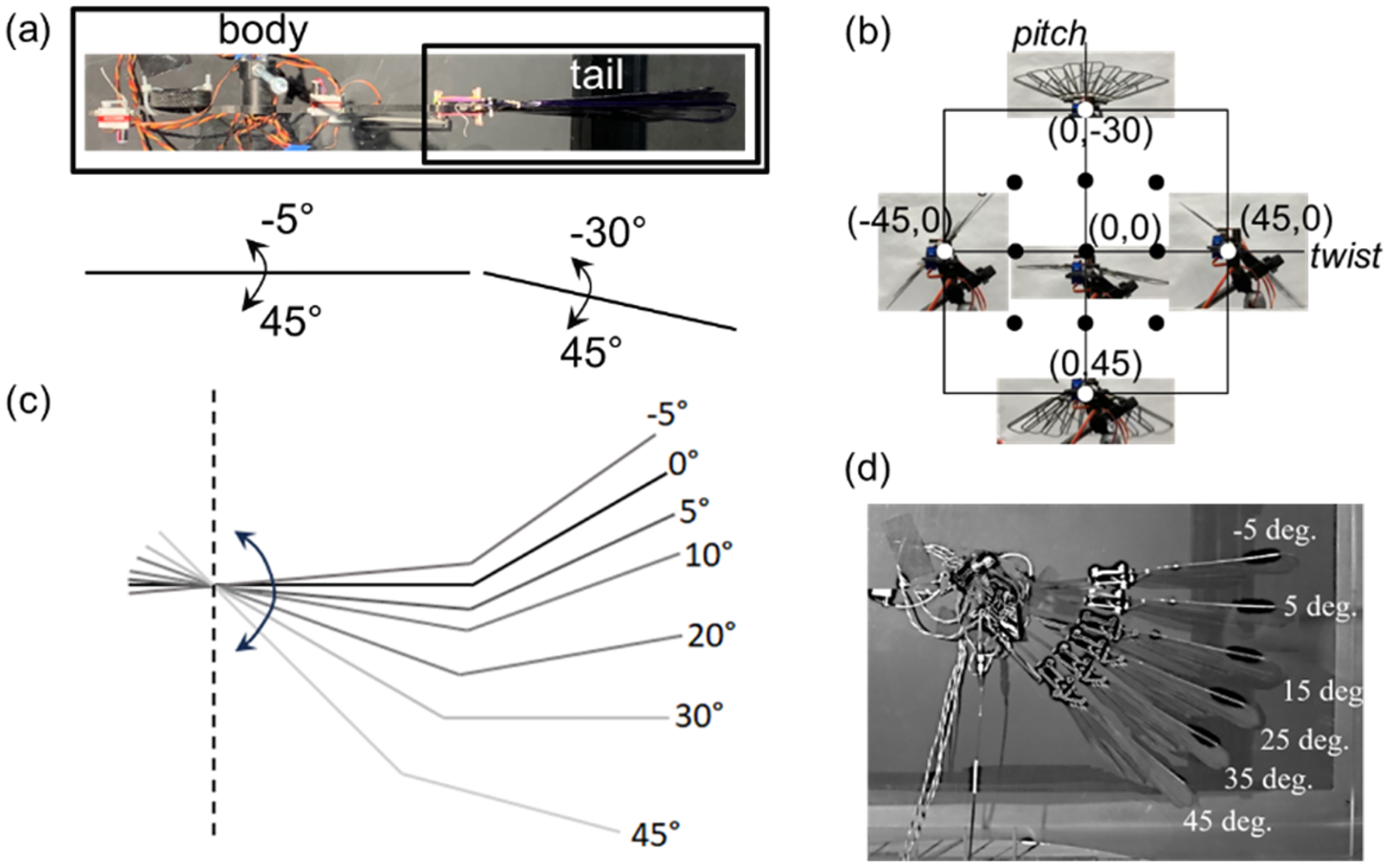
Wind tunnel diagram of (a) body-tail orientation as seen from the wind tunnel outfield (left is upstream) (b) tail twist-pitch orientations (13) from full up-left-right-down (4); middle (1); half up-left-right-down (4); and half combinations (4) (c) an example pitching of the model (−30 pitch 0 twist) (d) image stills of a 0 pitch 0 twist experiment.
Results and discussion
Wind tunnel testing
Aerodynamic force and moment data is presented in Figure 8 for tucked and splayed configurations with variations in pitch (left) and variations in twist (right). Error bars represent the experimental variation for the two pitching downwards and two pitching upwards trials. Pitch up or twist right and pitch down or twist left are signified with blue and black coloring respectively. Pitch down created more drag and lift than the middle configuration; however, the tail was stalled and eventually resulted in zero lift when the body was positioned at 45° angle of attack since the tail was orthogonal to the flow. Increasing the tail area via splay increased the nominal force and moment generation.

Aerodynamic force and moment results for tucked and splay configurations with variations in pitch (left) or variations in twist (right) at a wind tunnel speed of 5 m/s.
The pitching moment here was positive for pitching nose-up and negative for pitching nose-down. As angle of attack increased, the pitching moment changed from positive to negative for the upward pitched tail; however, a downward pitched tail produced minimal change in pitching moment due to stall. During tail twisting, side force generation was generally below half the magnitude of lift and drag, producing a maximum yaw moment with the same order of magnitude as the pitching moment. Although not shown here the only unaffected moment was roll, which was always approximately zero.
Since the local angle of attack of the tail was a function of both the tail pitch angle and the body angle, the data was combined using the local incoming flow angle for the tail (Figure 9). The aerodynamic coefficients collapsed for the tucked (black) and splayed (blue) configurations fairly well for both the longitudinal and lateral coefficients. When the x-axis was changed from body angle to an effective angle of attack of the tail (body angle + tail angle) the longitudinal coefficients created a continuum response across angles −35° to 90°. A sharp aerodynamic stall condition was not observed here, which makes the response of the tail reasonably predictable using simplified models.

Aerodynamic coefficients data for tucked (black) and splay (blue) configurations. (a) 5 m/s pitch and twist changes. (b) 5 m/s longitudinal coefficients vs alpha effective.
Mixed conditions for the tail are able to maintain a similar longitudinal response while providing lateral side force and yaw moment introducing mechanisms for correcting for lateral perturbations like gusts even at high angle of attack (Figure 10).

Aerodynamic coefficients data for tucked (black) and splay (blue) configurations for mixed twist-pitch conditions. (a) 5 m/s mixed – longitudinal. (b) 5 m/s mixed – lateral.
Increasing the airspeed from 5 m/s to 7 m/s did not meaningfully change the aerodynamic coefficients measured (Figure 11). The increased pressure loading however did cause some pitch rotation in the ball-and-socket joint and flexure in the feathers, especially for very large angles of attack. The post-stall behavior also became more noisy with a large coefficient of deviation which probably hides any compliance effects. However, operation at these high angles is unlikely for steady flight conditions and would likely be used for highly unsteady drag production, possibly as a method for decelerating.

Longitudinal aerodynamic coefficients data for tucked (black) and splay (blue) configurations for 5 m/s and 7 m/s velocities. (a) 5 m/s pitch changes. (b) 7 m/s pitch changes.
All of the angles of attack presented in this manuscript are the command values. The actual shape of the joint-tail would hypothetically be equal to the command, however, compliance in the joint (e.g the ligaments stiffness & servos) and synthetic feathers results in differences. Figure 12 shows a side view image of the model at 15°, 25°, and 45° angle of attack command at 0, 5, and 7 m/s flow speed. The joint can be seen to flex starting at around 25° and 5 m/s with a maximal deformation of nearly 15° at 45° angle of attack and 7 m/s flow. In future work the true position could be perceived resulting in corrective larger current command to the servos to get to the desired position based on the relatively low current draw of 0.8 V for both servos when in 7 m/s flow (Figure A4). The deformation of the synthetic feathers is relatively small and any resultant loss in aerodynamic performance appears to be negligible.

Spine-tail morphology at a function of wind speed and angle of attack.
Conclusions
An articulated tail construction like the one presented in this manuscript can produce considerable changes in tail area to generate large drag forces and control moments at high angles of attack. Lift was found to decrease post-stall as angle of attack increased past around 40° with increased drag suggesting a slowing trajectory may be possible with this design while additional control via changing the tail area could make a vehicle more tolerant to both longitudinal and lateral disturbances. The ball-and-socket joint presented in this work allowed for unique twist-pitch control at the same axis of rotation, with both actuators acting to position the tail at high angles against drag and pitch. Compliance in the joint and synthetic feathers was observed to not have a significant adverse effect on the aerodynamic performance for the ligament and feather stiffness addressed in this manuscript.
The ball-and-socket design removes the need for any vertical elements to the tail to control side force and yaw. Additionally, any adverse lateral forces or moments such as those from gusts while at high angle of attack would be of lesser magnitude from the lower vehicle cross-sectional area and could be addressed by this design via twist without changing longitudinal performance. The aerodynamic performance was similar to a flat plate which significantly underperforms engineered airfoils. However, an articulated tail can greatly change tail area and compact tightly for stowing or launching. Future work could consider perception of current tail pose to account for compliance with additional servo command to reach target tail displacements.
Supplemental Material
Supplemental Material
Footnotes
Acknowledgements
The authors would like to acknowledge Dr David Lee for this assistance in setting up the experiment.
Author contributions
All authors contributed equally to the ideation of the research, research execution, and data collection as well as writing, and editing the manuscript. All authors read and approved the final manuscript
Funding
The authors disclosed receipt of the following financial support for the research, authorship, and/or publication of this article: This work was funded by DEVCOM Army Research Laboratory under it’s core mission funding.
Declaration of conflicting interests
The authors declared no potential conflicts of interest with respect to the research, authorship, and/or publication of this article.
Supplemental material
Supplemental material for this article is available online.
Appendix
Parts list and associated approximations of weight and volume content by the 3D printer slicing software eiger.io as well as measured weight. Parts are group into (a) the five-bar linkage, (b) the spine, and (c) the tail assembly (Table A1).
Parts list. Spine and tail mount technical drawings specifying dimensions for the five-bar linkage and ball-and-socket joint (Figure A1). Spine and tail assembly technical drawing.
measured
eiger.io estimate
weight
weight
onyx
carbon
part
qty
grams
grams
cm3
cm3
a-ball
1
0.11
0.10
0.09
0.00
a-servo link
2
0.56
0.60
0.92
0.08
a-tail link A
1
2.15
2.31
2.22
0.32
a-tail link B
1
2.13
2.26
2.36
0.29
b-X08H
3
9
9
b-spine
1
18.16
19.99
15.48
2.26
c-tail mount
1
4.62
5.17
6.88
0.89
c-T1
1
2.99
3.28
1.24
1.46
c-TR2
1
2.76
3.01
1.26
1.35
c-TR3
2
2.83
3.00
1.24
1.35
c-TR5
1
3.04
3.24
1.34
1.44
c-TL2
1
2.75
3.01
1.26
1.35
c-TL3
2
2.83
3.01
1.25
1.35
c-TL5
1
3.04
3.22
1.33
1.44
sum
81.19
85.81
36.87
13.58
structure
%
66.7
68.5
actuator
%
33.3
31.5

Synthetic feather dimensions are similar to 27 with inspiration draw from the goshawk reduced in length for wind tunnel accommodation (Figure A2). The minimum outside dimension was drawn at 3 mm to allow for 3 paths of CCF around the feather perimeter.
The inter-feather working force was approximately 1 to 2 N across 14 to 19 mm for two “tail ligaments”. A single ligament for the ball-and-socket working force was approximately 2.25 to 2.75 N across 35 to 40 mm for the tail movement under investigation in this manuscript (Figure A3).
Model current draw from the power supply was a nominal 100 mA from all three servos with the wind tunnel off and the tail in the middle configuration. The current draw increased with increasing pitch and with increasing wind speed to a maximal value of 600–800 mA Figure A4)
Pitch change conditions data for coefficients of lift and drag are plotted in Figure A5 for 5 m/s (top) and 7 m/s (bottom) with similar results.
Outfield-side view images of the model at 0, 5, and 7 m/s across the vertical and 0, 5, 15, 25, and 45° across the horizontal axis of Figure A6 are presented for the middle (top) and maximum pitch down configuration (bottom). Control of the tail position as a function of air pressure in future work will require feedback if proprioceptive information is required although aerodynamic information suggests that the difference in 5 and 7 m/s aerodynamic coefficient data is minimal within the measurement scatter. Based on Figure A4 the current draw of the servos is not at the stall torque therefore it should be possible to increase servo command to reach target pitch locations as a function of air pressure. Figure A6 also shows some bending compliance in the artificial feathers themselves especially at very high angles and speeds.
References
Supplementary Material
Please find the following supplemental material available below.
For Open Access articles published under a Creative Commons License, all supplemental material carries the same license as the article it is associated with.
For non-Open Access articles published, all supplemental material carries a non-exclusive license, and permission requests for re-use of supplemental material or any part of supplemental material shall be sent directly to the copyright owner as specified in the copyright notice associated with the article.