
Abstract
This study proposed a quadcopter equipped with flaps designed to attach to and move along walls, enabling safe photography of square-shaped bridge piers. It was verified through experiments whether flaps can generate sufficient and continuous force in the direction of the wall. Additionally, a mathematical model of the quadcopter with flaps was developed using lift and drag measurement data. Through simulations, it was confirmed that the drone could be controlled using the lift generated by the flaps. A prototype quadcopter with applied flaps was then created. An algorithm for processing essential sensor signals, such as attitude and speed, was presented for effective quadcopter control. Moreover, an algorithm utilizing two distance sensors was proposed to measure the angle and distance between the quadcopter and the wall. A controller was also designed to effectively manage the speed and yaw angle of the quadcopter. The developed quadcopter was validated through real experiments, demonstrating its ability to attach to walls and move along the bridge structure.
Introduction
With rapid industrialization and economic development, the number of domestic bridges has increased significantly. As of 2022, the total number of bridges in the country is about 37,000. Among these, approximately 5700 bridges have been in use for over 30 years, accounting for 15% of the total. While the current situation is manageable, projections indicate that in 10 and 20 years, these numbers will rise to about 17,000 and 29,000, respectively, making up 47% and 80% of the total. This suggests that the problem of bridge aging will become severe. 1 Consequently, the maintenance cost for bridges has steadily increased over the years, from about 770 billion won in 2000 to approximately 2.8 trillion won in 2010. 2
The number of bridges in need of maintenance is increasing, and the costs are rising, but the number of maintenance workers is insufficient. Bridge maintenance is labor-intensive, but young people are currently avoiding these jobs, viewing them as part of the undesirable “3D” industries (dirty, dangerous, and demanding), which has led to an aging workforce.
Inspecting cracks in bridges, in particular, requires human inspectors to approach the structures and visually identify and mark cracks’ presence and thickness. Recently, drones have been developed to assist with this task by photographing bridges to detect cracks. For optimal image quality and accurate measurement of crack dimensions, it is beneficial for drones to be securely positioned relative to the bridge. Additionally, the ability for the drone to maneuver around the bridge is crucial for comprehensive inspections. Various research teams have explored methods to attach and move drones on walls, such as horizontally rotating the drone itself, 3 using tilt-rotors, 4 or employing auxiliary arms. 5 Studies have also developed spherical drones with flaps6,7 and other innovative drones for structural inspections.8–12
This paper proposes a drone system capable of horizontal movement and wall attachment by incorporating flaps into a quadcopter. The principle involves placing a cross-shaped flap at the bottom of each propeller to generate horizontal force, as well as producing a yaw moment. An algorithm is introduced to estimate the angle and distance between the drone and the bridge wall using two distance sensors, alongside a soft-landing control algorithm for gentle wall landings. The design features a quadcopter with flaps and a method to control the angle of attack of these flaps. Experimental results demonstrate the feasibility of wall attachment and movement on wall surfaces for the designed quadcopter.
Unlike the existing wall-attaching drones,3–5 The proposed wall-attaching quadcopter is structurally simple, lightweight, and easy to control, in terms of wall attachment. Thereby reducing electric energy consumption and extending flight time. Additionally, while most drones can only move vertically along walls, the proposed drone can move both vertically and horizontally using omni-wheels. Therefore, this drone system is more optimized for detecting cracks in square-shaped bridge piers, offering greater mobility and efficiency compared to existing wall-mounted drones.
Theoretical background
Flaps generating force
A quadcopter uses its propellers to accelerate air toward the ground, which in turn lifts the drone into the air. During this process, a fast airflow occurs at the bottom of the rotor. By adjusting the angle of attack of the flaps, the direction of this airflow is altered, generating a force in the opposite direction. This principle is similar to how a fixed-wing airplane generates lift. The resulting lift,

Where

Principle of generating horizontal force using flaps.
Designing flap geometry
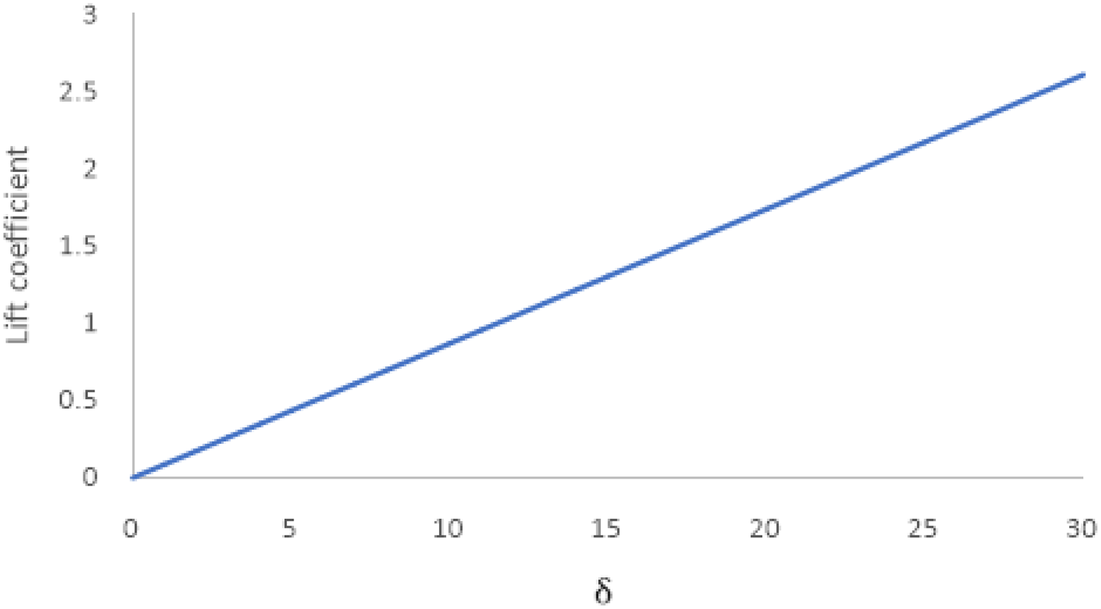
The force generated by the flap depends on the shape and angle of attack of the airfoil. As shown in Figure 1, the flap can move the drone horizontally, and to move the drone in the opposite direction, the flap can be rotated to the opposite angle of attack. In this case, a symmetrical airfoil shape was selected to ensure that the force generated by the flap is equal in both directions.
When selecting the airfoil shape, the website Airfoil Tools 13 was used to find the lift coefficient based on the airfoil shape, Reynolds number, and angle of attack. We selected the NACA 16-021 airfoil, developed by NACA, as it has the largest lift coefficient for the same angle of attack. The flap was designed with a chord length l of 75 mm, a maximum thickness h of 15.75 mm, and a span w of 135 mm. Figure 2 shows the 3D design of the flap from perspectives ① and ②. The flap is positioned on the lower part of the propeller in a cross shape and is designed to avoid interference with other flaps when adjusting the angle of attack.

Flap shape geometry.
Equations of motions
Modeling of a typical quadcopter
Many studies have been conducted on quadcopter modeling.14–21 The inertial coordinates (

Inertial and body frames of quadcopter.
The quadcopter can be considered a rigid body, and its translational motion can be expressed in inertial coordinates, accounting for gravity, rotor thrust, and air resistance, as shown in Equation (2). Where m represents mass of the quadcopter, R is the rotation matrix from the quadcopter's body coordinates to the inertial coordinates, g denotes the gravitational acceleration, T is the sum of the four rotor thrusts, and

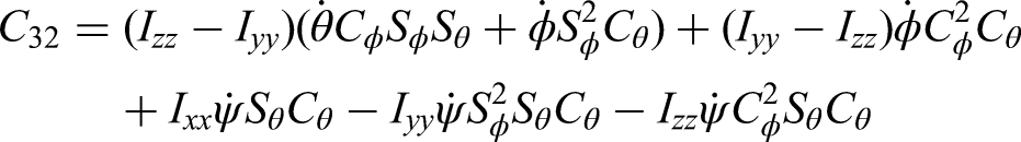
Furthermore, the attitude of the quadcopter is defined in inertial coordinates using three Euler angles


Here,


A proportional (P) controller is designed to control the altitude and attitude of the quadcopter. The P-P controller is a type of cascade control, where the output of the attitude P-controller serves as the input for the angular velocity P-controller in the case of attitude control. The total thrust for altitude control and the torque for each axis for attitude control are modeled as shown in Equations (7) to (10). In this case,


Model of a quadcopter with flaps
The lift


In our work, the lift and drag forces, lift coefficient and drag coefficient for the angle of attack of the flap were obtained through experiments. This can be used to mathematically model the lift and drag produced by the flap. First, the lift coefficient is not significantly different for angles of attack above 30°, so we only used angles of attack within 30. We also assumed that since the airfoil is symmetrical, the lift coefficient from 0 to 30 is negative and of the same magnitude as for angle of attack from 0° to −30°.
For ease of interpretation and control, the lift coefficient in the 0° ∼ 30° range was fitted as a quadratic function,


Actual and fitted lift coefficients.
We fit the lift coefficient as a quadratic function, but it is still nonlinear with respect to the angle of attack. If this could be modeled linearly for an arbitrary number
Therefore, to linearize this lift coefficient, we define an arbitrary first-order function

To find

With
Linearized lift coefficient.
The drag coefficient is more complex than the lift coefficient, so we linearly interpolated it.
The speed of air flow through a propeller is proportional to the rotor speed. To understand the relationship between rotor speed and air speed, we directly measured the air speed for various rotor angular velocities. Figure 6 shows the rotor speed versus air speed. Since the rotor speed and air speed closely follow a first-order function, we interpolated the best-fit first-order function for the simulations.

Wind speed measurement according to the rotor angular velocity.
Furthermore, the rotor speed


We formulated a model for a typical quadcopter as described in equations (2) to (6). A quadcopter with flaps is modeled by incorporating the lift and drag forces generated by the flaps, as well as the moments generated by these forces. In the second term on the right-hand side of equation (2),

Lifts generated by flaps.

Distance between center of mass and line where lift generated.

Drags generated by flaps.
The lift force,


In this case, drag

Using this, (2) is modified to (24).

In addition, torques are generated in the roll and pitch directions because the position where the lift force is generated is lower than the center of gravity. Torque is also generated in the yaw direction due to the difference in the amount of flap in the x and y directions. The torque generated at this time can be summarized as shown in equations (25) to (27)


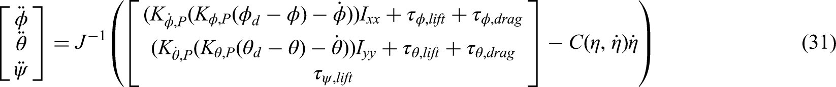
Torque is also generated by drag, which is equal to (28) to (30).


Using (28) to (30), (4) is modified as (31).
Simulation results
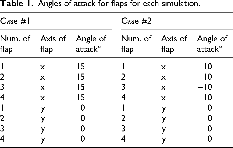
After setting the flap's angle of attack, we conducted a 10 s simulation. For each simulation case, the first 5 s were spent with the angle of attack set to 0° to allow the altitude to stabilize. After 5 s, the flap angles were varied to observe changes in position and attitude. The input flap angles for each simulation are shown in Table 1, and the results for each case are presented in Figures 10 and 11.

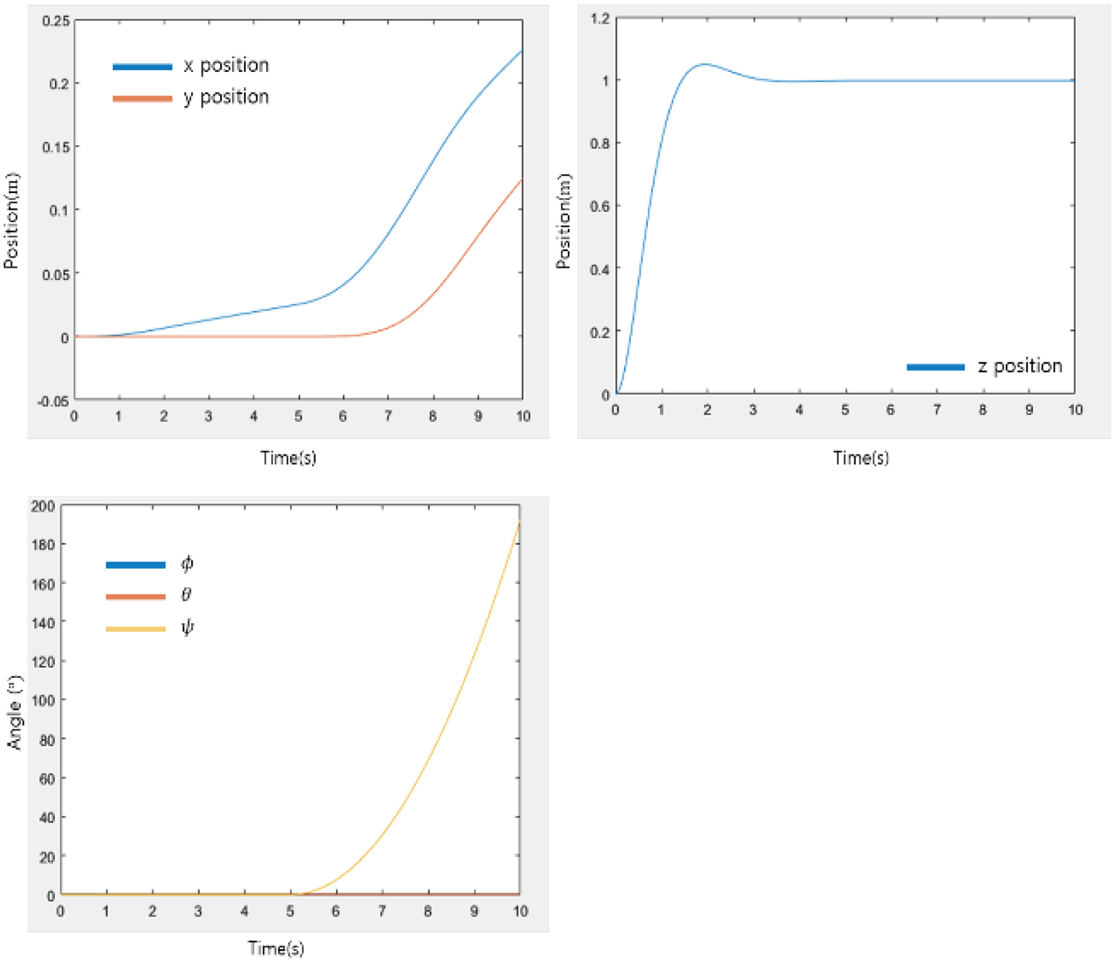
Simulation results for case #1.
Simulation results for case #2.
Angles of attack for flaps for each simulation.
As a result of case #1, we see a steady increase in position along the x-axis after 5 s. At this time, the altitude is slightly reduced due to drag, and the pitch is tilted by about 0.8°. In case #2, we can see that reversing the angles of flaps 1, 2 and 3, 4, respectively creates a torque in the yaw direction.
Modeling speed and yaw control with flaps
The lift generated by the flaps is used to model the speed and yaw controllers in the x and y directions. In the actual quadcopter, flaps 1 and 2 in the x direction are controlled simultaneously by a single servomotor, so they have the same angle of attack. Flaps 3 and 4 are also driven by another servomotor to control all the y-direction flaps simultaneously. At this time, we define the angle of inclination of flaps 1 and 2 in the x direction as
We designed a speed controller for the x and y directions. The lift force generated by the flaps forms a complex nonlinear system, influenced by various factors such as angle of attack, propeller speed, and air density. To manage this complexity, we implemented a P controller to generate the angle of attack, excluding model-based control design. The P controller calculates the difference between the target velocity of the quadcopter and its current velocity. The output is the angle of attack for the corresponding axis, which can be represented as shown in (32–34).


After each angle of attack was calculated, we constrained the value to −30° if it was less than or equal to −30° and to 30° if it was greater than 30°. The control gains were found by trial and error throughout simulations, and the final control gains are shown in Table 2.
Gains for velocity and yaw controller.

The simulation was run for a total of 10 s. During the first 5 s, the altitude was stabilized. After this initial period, the target speed and yaw control input values were applied. The input values used for each simulation case are shown in Table 3, and the results are presented in Figures 12 and 13.

Simulation results of velocity and yaw control for case #1.

Simulation results of velocity and yaw control for case #2.
Linear velocities and yaw angles for each case.

In case #1, the simulation results show that the quadcopter follows the speed command well in both the x and y directions, as well as the yaw control, without significant changes in altitude and attitude. In case #2, the results indicate that the quadcopter effectively follows each input, even when all three controls are commanded simultaneously.
These findings confirm that it is possible to control the x and y speeds and the yaw of the quadcopter using flap control.
System configurations
Hardware configurations
A flap was placed at the bottom of each rotor in a cross (+) configuration, and ball casters were used for wall attachments to allow the quadcopter to move freely on the piers. The flaps were fabricated using a 3D printer, and carbon rods were used to secure them. The overall geometry of the quadcopter is shown in Figure 14, and the specifications are listed in Table 4.
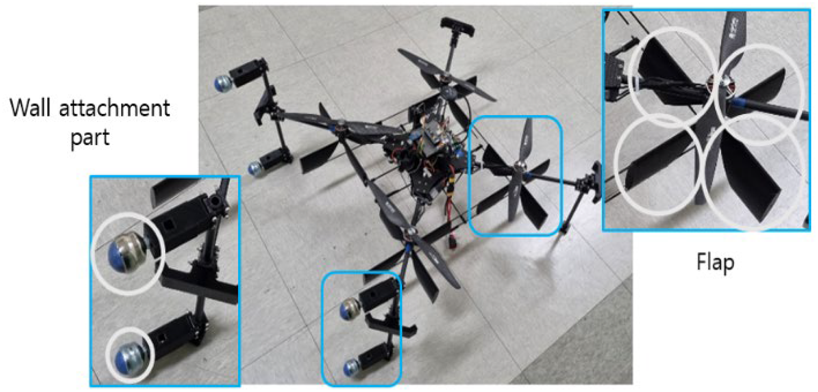
Structure and shape of quadcopter adapting flaps.
Specifications of the developed quadcopter.

Servomotors were used to adjust the angle of attack of the flaps. The flaps are arranged in a cross shape at the bottom of each rotor, requiring a total of 8 servomotors to control all the flaps in the x and y directions. To reduce the number of servomotors needed, we implemented a structure that uses two servomotors on the left and right sides of the quadcopter to control the flaps in the x direction and one servomotor to control the flaps in the y direction. This setup allows us to control the flaps with just three servomotors.
Both flaps are connected by a carbon rod and linked in such a way that when the servomotor's axis rotates, the flaps move together. Figure 15 shows the flap control structure using servomotors.
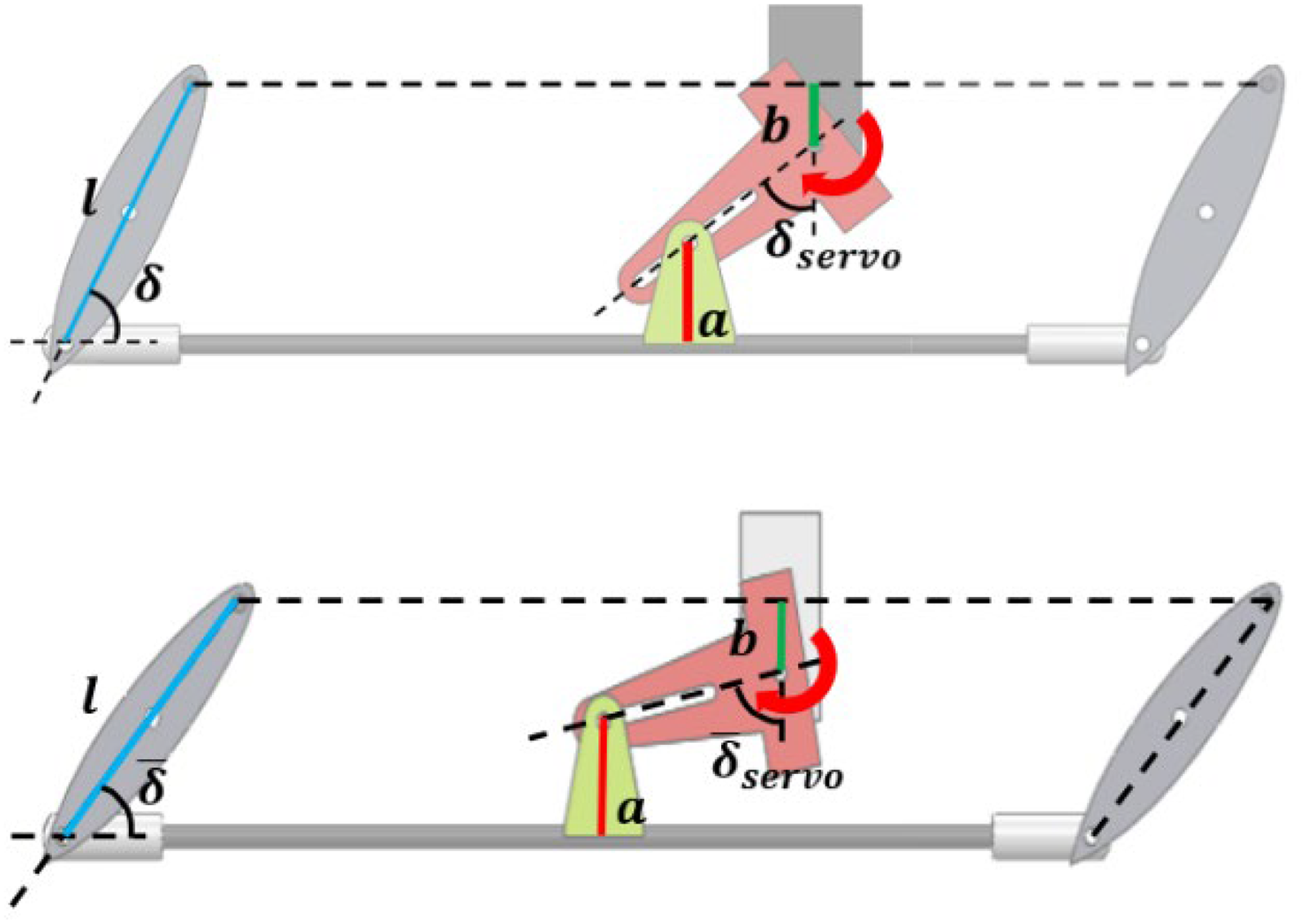
Structure of controlling angle of attack of flap using servo motor.
Since the servomotor rotation does not directly correspond to the angle of attack of the flap, the actual angle of attack must be calculated to achieve the desired position. This relationship can be expressed as shown in equation (35), where 
Pixhawk4 was used as the flight controller (FC) to fly the quadcopter. We used Pixhawk4's attitude and altitude control mode to control the quadcopter's roll, pitch, and altitude. To control the horizontal direction and yaw of the quadcopter, we controlled the flaps and designed a system for the flap control. An IMU sensor and an optical flow sensor were used to estimate the attitude and speed, and two distance sensors were used to estimate the orientation and distance between the quadcopter and the wall. Figure 16 shows the overall system block diagram.
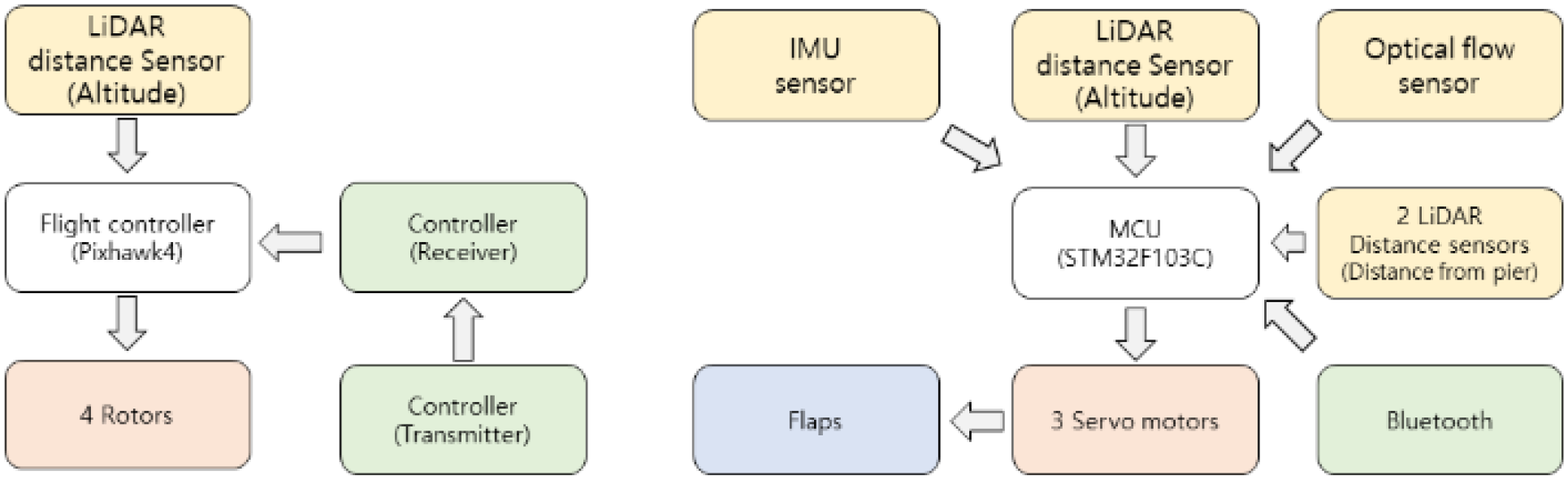
Structure of entire control system of quadcopter.
The product name and purpose of each part is shown in Table 5. To control the quadcopter with flap, we need to know several physical quantities. Some quantities can be estimated directly from specific sensors, while others need to be estimated by fusing data from multiple sensors.
Parts and models of the developed quadcopter.

Estimate the angle and distance between a vertical wall and velocity of a quadcopter
In order to land a quadcopter on a vertical wall, the orientation angle between the vertical wall and the quadcopter must be known so that it can be controlled horizontally while parallel to the floor. For this purpose, this work used two LiDAR distance sensors facing the vertical wall. The resolution of the Lidar sensor is 1 cm, and when the quadcopter is attached to the wall, the distance between the sensor and the wall is about 50 cm. Therefore, if the sensor is arranged parallel, it cannot secure sufficient angle resolution. Hence, it is necessary to increase the distance between the sensor and the wall that it detects, and this was achieved by arranging it crosswise. The angles

Diagram of installing two distance sensors.
Letting 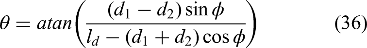
Additionally, the distance 
To verify the accuracy of the angle between the wall and the quadcopter obtained above, a simple experimental setup was constructed. The setup is shown in Figure 18, where the distance sensors are mounted at specific angles and distances from each other, and an IMU sensor is attached to compare the angular velocity integral with the algorithm.

Experimental device to measure tilt angle and distance between quadcopter and vertical wall.
The experimental setup was rotated against a vertical wall. During this process, the angle measured by the IMU sensor was compared with the estimated angle, and the experimentally set distance of 1.5 meters was compared with the estimated distance. Figures 19 and 20 show the results.

The estimated values compared with the IMU sensor values.

The estimated values compared with set value 1.5m.
To estimate the velocity of the quadcopter, we used an optical flow sensor. The sensor was attached to the bottom of the quadcopter and pointed downward. The optical flow sensor can be used to estimate the velocity as shown in (38).
Controller design
The simulation demonstrated that it is possible to control the x and y speeds and the yaw of a quadcopter using flaps. To apply this to a real quadcopter, we designed controllers. The speed controller is implemented as a P-I controller, while the yaw controller is designed as a P-P controller for both normal flight and when attached to a bridge wall. The control output of each controller is the angle of attack of the flap, calculated as shown in Equations (32) to (34).
The speed controller design is illustrated in Figure 21. The difference between the target speed and the speed estimated through optical flow is multiplied by the control gain to adjust the angle of attack of the flap, thereby controlling the speed through the generated lift. Although a P controller was used during the simulation stage, an I controller was added to compensate for disturbances such as wind effects.

Block diagram of velocity control.
Additionally, we designed a P-PI (Proportional and Integral) controller for soft-landing control. This involves adding a P-controller to manage the distance from the vertical wall, outside the speed controller, to gradually reduce speed as the quadcopter approaches the wall for a smooth landing. This design is shown in Figure 22.

Block diagram of soft-landing control.
We also designed a yaw controller, as depicted in Figure 23. During flight, the yaw angle is estimated from the IMU. When attached to a bridge wall, the yaw angle is determined using the orientation angle estimation algorithm with two distance sensors, as proposed in Section 4.2.1. Figure 24 shows the P-P yaw control utilizing the estimated orientation angle between the vertical wall and the quadcopter.
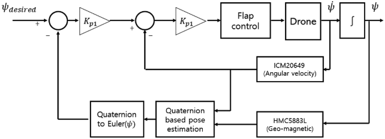
Block diagram of yaw control.

Block diagram of P-P control about tilt angle between vertical wall and quadcopter.
Experimental results
To measure the lift generated by the selected airfoil NACA 16-021, an experimental apparatus was constructed. A rotor and flap were attached to the end of the profile, and a flap angle adjuster was fabricated to facilitate angle adjustment of the flap. When the flap generates lift toward the ground, a moment is generated in the profile, and the lift is measured by measuring the force using a load cell at the part of the profile opposite the flap. At this time, the distance between the flap and the load cell from the rotating part is equal so that the measured force becomes the lift force. The angle adjustment part is designed to be freely adjustable using bolts when the size of the attack angle of the flap is less than 15°, and fixed at 5° intervals from 20° to 45°. Figure 25 is a picture of the experimental apparatus.

Apparatus for lift force measurement.
875gf of thrust was generated from the rotor to hover a 3.5 kg quadcopter and measured lift by adjusting the angle of attack. The air speed measured using an anemometer was 8.1 m/s. The angle of attack was adjusted in 1° increments from 0° to 15° and in 5° increments from 15° to 45°. The lift measurement results are shown in Figure 26. The maximum lift of 80gf occurs at an angle of attack of about 30° to 40°.

Lift force according to angle of attack.
Using the above experimental results, the lift coefficient of the airfoil was obtained from (1). Solving (1) for the lift coefficient, 
The air density

Lift coefficient according to angle of attack.
Similar to a lift meter, a drag meter consists of a rotor, an angle adjuster, bearings, and a load cell, as shown in Figure 28. By separating the rotor from the flap, the thrust of the rotor is not measured by the load cell so that only drag is measured. The measured drag is shown in Figure 29. Furthermore, the drag coefficient 
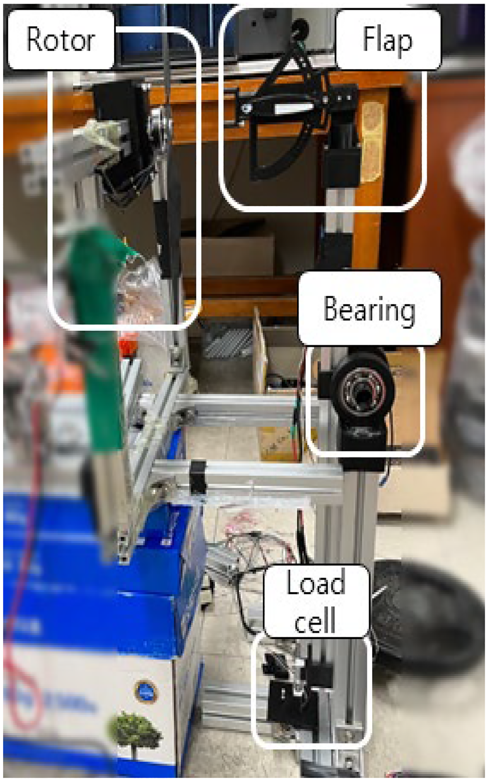
Device for lift force measurement.

Drag force according to angle of attack.

Drag force coefficient according to angle of attack.
Attaching to and moving on a vertical wall
If the yaw angle between the vertical wall and the quadcopter falls outside the range of −5° to 5° during attachment, soft-landing control should not be initiated, and the speed should remain at zero. Control efforts are directed towards achieving a 0° angle between the vertical wall and the quadcopter. Soft-landing control initiates only when the angle is within the range of −5° to 5°. The experiments were conducted in the basement of the Frontier Building at Seoul National University of Science and Technology. Figure 31 illustrates the horizontal movement along the vertical wall, ***while Figure 32 presents the sequence of soft-landing onto the wall. Figure 33 depicts the measured orientation angle between the quadcopter and the vertical wall during attachment, and Figures 34 and 35 show the quadcopter's velocity and the distance between the quadcopter and the vertical wall.

Sequences of controlling the tilt angle.

Sequences of soft-landing control to the wall.

Measured orientation angle during wall attaching.

Measured velocity during soft-landing.

Measured distance to wall during soft-landing.
Before initiating soft-landing control, the quadcopter adjusts its speed and yaw using the remote controller to orient the attachment mechanism towards the wall. Once the soft-landing command is issued, it automatically attaches to the wall through the soft-landing sequence. After attachment, altitude control and lateral direction control become available via the remote controller.
We confirmed the experimental results of the quadcopter moving parallel to the floor while being attached to a vertical wall. The soft-landing result shows the quadcopter slows down as it approaches the vertical wall and lands softly on the vertical wall.
After landing on a vertical wall, the x-directional (wall-facing) flaps are turned to 30° to generate maximum lift in the direction of the vertical wall. Altitude is then controlled by Pixhawk's altitude controller and side-to-side movement is controlled by the y-rate controller using the flaps. Figure 36 shows side-to-side and up-and-down movement while attached to a vertical wall.

Sequences of wall-attaching and moving on the wall.
Wind resistance experiments
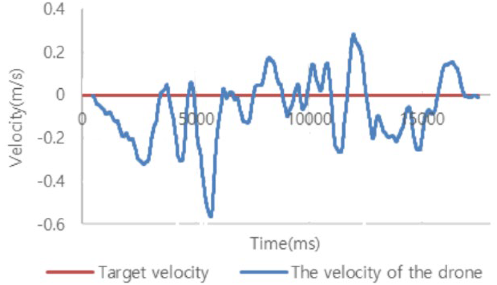
The experimental environment described so far is an idealized windless environment, but real piers have disturbances such as wind. To test whether this could be overcome, we created a windy environment using a fan and attached it to a vertical wall. The experiment was conducted at the quadcopter test site on the roof of the building, and the aircraft was attached to a vertical wall and blown by an electric fan. At this time, the angle of attack of the y-direction flap was set to a maximum of 30 degrees. The wind generated by the fan is about 3 m/s ∼ 4 m/s, and the natural wind is about 1 ∼ 3 m/s. When the angle of attack is neutral, the experimental results are shown in Figures 37 and 38. It can be observed that the quadcopter is drifting to the right due to the crosswind. When the angle of attack is set to 30°, as the experimental results are shown in Figures 39 and 40, it can be seen that the quadcopter is not pushed by the wind.

The quadcopter motion flowing to the right without attack angle control.

Quadcopter velocity showing the quadcopter flows to the right without attack angle control.

Quadcopter overcoming wind using flaps attack angle control.
Quadcopter overcoming wind using flaps attack angle control.
Attaching and moving walls on real piers
So far, it has been confirmed that wall attachment and movement are possible in environments other than an actual bridge. In this section, we experimentally verify that a quadcopter can attach to and move on an actual bridge wall. Additionally, we have confirmed whether the camera attached to the quadcopter can capture images of the bridge's wall cracks without any shaking.
The experimental site is a bridge of 4 meters wide and about 10 meters high. The experiment was conducted on the widest of the four sides of the bridge, and the weather was a little cloudy with a temperature of 20°C and a natural wind of 1 m/s to 2 m/s. The experiment was conducted by flying the quadcopter, attaching it to the vertical wall of the bridge, and moving it up and down. Figure 41 represents the experimental results of wall attachment and movement on an actual bridge structure. It can be observed that wall attachment and movement of the developed quadcopter were successful even on the actual bridge under external wind, confirming its feasibility.

Wall-attaching and moving test on an actual bridge wall.
The image of the bridge captured by the quadcopter is shown in Figure 42. It provides a clear view of the cracks on the bridge, and it is evident that the image was captured without any shaking.

Captured crack image during wall-attaching.
Conclusions
In this work, we proposed a quadcopter capable of attaching to and moving along vertical walls, such as square-shaped bridge structures, by applying flaps. Initially, through experiments, we confirmed that by utilizing flaps to control the airflow generated underneath the rotating rotors of the quadcopter, a sufficient amount of lift can be generated. Based on the data obtained from experiments, we established a mathematical model for the quadcopter equipped with flaps. Through simulations, we confirmed that by controlling the flaps, it is possible to achieve control over horizontal and vertical velocity as well as yaw control.
To verify that the quadcopter can actually attach to a vertical wall and move along it, we built a quadcopter with flaps underneath each rotor, and adjusted the angle of attack of the flaps using servomotors. To know various physical quantities for control, we estimated the attitude using a quaternion-based complementary filter, and developed an algorithm to estimate the orientation angle and distance between the quadcopter and the vertical wall using two distance sensors facing the vertical wall. We also estimated the linear velocity of the quadcopter in the horizontal and vertical directions using an optical flow sensor. Using this, we designed a controller for moving speed, soft-landing to a wall, and a yaw angle adjustment.
Through the use of flaps, we achieved control to keep the quadcopter parallel to the ground and implemented soft-landing control to securely attach it to the wall and enable movement along the wall surface. Additionally, we verified that even in the presence of wind speeds ranging from 3 to 5 m/s, the use of flaps allowed us to overcome these conditions. Furthermore, we confirmed the feasibility of attaching to and moving along an actual bridge structure.
The lift generated by the airflow in the rotor and flap structure proposed in this study is influenced by various environmental factors such as air density, rotor RPM, wind conditions, and the attack angle of the flap. It is a complex and highly nonlinear phenomenon. Therefore, for dynamic control, the approach proposed in this study may have its performance limitations. Subsequent research is necessary for stability analysis of the control system and the design of controllers based on nonlinear models to address these challenges.
The quadcopter developed through this study, capable of adhering to and moving along real bridge structures while capturing stable photos, can have a significant impact in reducing the cost and time required for bridge inspections. Furthermore, the quadcopter proposed in this research can find applications in various specialized fields, offering versatility and potential for a wide range of uses.
Additionally, the quadcopter proposed in this paper is only effective on flat, square-shaped piers due to the ball caster structure used for wall attachment and the algorithm for measuring distance and angle to the wall. Therefore, further research will be necessary to adapt this system for use on piers with various wall shapes.
Footnotes
Acknowledgements
This research was supported by Korea Institute for Advancement of Technology(KIAT) grant funded by the Korea Government (MOTIE) (P0008473, HRD Program for Industrial Innovation) also was the result of the “Regional Specialized Industry Promotion Project + (R&D)” (S3262070) conducted by the Ministry of SMEs.
Funding
The author(s) received no financial support for the research, authorship, and/or publication of this article.
Conflicting interests
The author(s) declared no potential conflicts of interest with respect to the research, authorship, and/or publication of this article.