
Abstract
Piers play a crucial role in transferring loads in bridge structures. Preserving these structures against hazardous loading is therefore important for ensuring their resilience. Current studies do not fully explain reinforced concrete (RC) piers’ dynamic behavior and failure modes under sequential vehicle impact and seismic loading. Bridge systems face increased risks from multiple extreme events, as vehicle collisions can compromise pier integrity, reducing seismic resilience. This research aims to address this gap by analyzing combined effects of these hazards. A case study is carried out that creates a three-dimensional finite element (FE) model of a cast-in-place (CIP) half-scale pier in LS-DYNA, based on typical prototype highway bridges in Utah, U.S. The FE models are validated against experimental results, showing good agreement. To assess the residual seismic capacity of RC piers after an impact event, the model underwent a sequential loading protocol: an initial impact load to simulate accident damage, followed by quasi-static cyclic loading to simulate seismic activity. During cyclic loading, post-impact piers displayed distinct damage patterns compared with undamaged piers, with shear cracks and concrete spalling causing early failure. CIP piers can withstand vehicle impacts from up to 0.9 ton (0.82 metric ton) vehicles at 22 mph (35.4 km/h), to meet Caltrans Seismic Design Criteria (SDC) requirements. However, higher impact conditions compromise structural integrity. An impact from a 0.9 ton (0.82 metric ton) vehicle at 31 mph (49.9 km/h) results in a reduced ductility response from 8.2 to 1.7, and an impact from a 2 ton (1.81 metric ton) vehicle at 22 mph (35.4 km/h) results in a reduced ductility response of 2.8. In both cases, the calculated ductility fails the SDC requirement and American Association of State Highway and Transportation Officials (AASHTO) Guide Specifications for Load and Resistance Factor Design (LRFD) Seismic Bridge Design.
During the design service life of 75 years, bridges inevitably suffer from various natural hazards (e.g., earthquake, flood, hurricane, landslide/debris flow) or human-caused hazards (e.g., vessel collision, vehicular collision, fire, explosion) ( 1 ). With the increasingly frequent occurrence of collision accidents, vessel and vehicle impact events have become the third leading cause of bridge failures in the U.S. for the 39-year period between 1967 and 2006 ( 2 ). As of 2012, bridge systems in 42 of the 50 states had suffered serious damage caused by truck collisions. Furthermore, 80% (40 out of 50) states had reported accidents resulting in minor bridge damage and 60% (30 out 50) had reported minor scrapes resulting from vehicle collision ( 3 ). While the majority of the existing literature studies the behavior of piers under impact to prevent catastrophic failure, few studies have evaluated their post-impact capacity to withstand subsequent hazardous loading events.
Since 2005, a lot of attention was given to the dynamic performance of reinforced concrete (RC) bridges under vehicle impacts and seismic events. Kim et al. presented a nonlinear finite element (FE) analysis procedure for the assessment of seismic damage of RC bridge piers ( 4 ). The proposed numerical method was verified by comparison with reliable experimental results, demonstrating its effectiveness in assessing seismic damage. Sharma et al. developed a framework to estimate the dynamic shear force capacity and demand on RC piers under vehicle impact for various performance levels ( 5 ). This dynamic analysis improved on static methods, offering a realistic representation for designing RC piers to minimize damage and meet performance objectives. The methodology could be extended to other structural members and high-velocity impacts. Abdelkarim and ElGawady studied the behavior of RC bridge piers subjected to vehicle collisions ( 6 ). They conducted an extensive parametric study, focusing on peak dynamic force and equivalent static force during collisions. AuYeung and Alipour analyzed the behavior of bridge piers under vehicle collisions, considering factors such as vehicle mass, velocity, pier diameter, and transverse reinforcement ( 7 ). Using LS-DYNA for simulation, they found that pier diameter dictated the overall failure mode, while transverse reinforcement influenced the degree of local failure. Zhao et al. investigated RC piers’ dynamic behavior and damage mechanisms under truck impact using LS-DYNA simulations ( 8 ). Model accuracy was verified against tests and real collisions. Comprehensive simulations examined impact forces, internal forces, failure modes, and truck type effects, illustrating typical failure processes and providing insights into dynamic performance. Chen et al. conducted six successive lateral impact tests on a full-scale RC pier ( 9 ). The study obtained impact forces, displacements, accelerations, and damage patterns, and validated FE simulations, revealing issues with common techniques, and discussed multiple impact effects. Bridge systems are often exposed to multiple extreme events, either concurrently or as a cascade of two or more hazards ( 10 ). However, the current studies are not sufficient to comprehensively explain dynamic behavior and failure modes of RC piers under sequential vehicle impact and seismic loading.
Consider a real scenario where an RC pier is subjected to a vehicle collision to illustrate the significance of this issue. Even if the pier’s exterior does not display any obvious damage, the collision could have compromised its capacity to effectively transfer future loads. The collision could have reduced a bridge system’s capacity to withstand future hazardous loading conditions such as seismic events and other subsequent extreme events. Consequently, the bridge becomes vulnerable, exposing it to increased risks during subsequent extreme events. Understanding the failure mechanisms of piers and their residual seismic capacity is crucial. This knowledge forms the foundation for ensuring residual seismic capacity and protecting the safety of piers against sequential hazards. This research is the first to explore a modeling strategy for sequential vehicle impact and seismic loading on RC piers, evaluating their post-impact capacity. The study provides insights into how impact-damaged piers behave under subsequent seismic events, offering guidance for bridge design, maintenance strategies, and resilience assessment.
FE Model Calibration
This section provides a detailed description of the modeling techniques employed. To evaluate the suitability of this study’s modeling techniques for simulating the seismic behavior of RC piers, a three-dimensional (3D) FE model of cast-in-place (CIP) half-scale pier is created in LS-DYNA. The developed FE models are validated against experimental results (half-scale test items) from Pantelides et al. through several key characteristics: hysteresis curves, average skeleton curves, and the analysis of crack development at critical drift ratios ( 11 ). The validation process shows good agreement between the FE analysis and experimental results in pushover stages. This help confirm the accuracy and reliability of the FE models in simulating the seismic behavior of RC piers.
Geometry Information of Half-Scale Piers
In the study by Pantelides et al., half-scale pier-footing joint specimens were designed following typical prototype highway bridges found in Utah, U.S., with dimensions, longitudinal bars, and configurations scaled to approximately 50% of the prototype properties ( 11 ). The test specimens were constructed as half-scale models to ensure manageable laboratory testing. Each pier was 8 ft 6 in. (2.59 m) tall, with a 21 in. (533.4 mm) square cross-section at the top head, which measured 1 ft 6 in. (457.2 mm) in height, and a 7 ft (2.13 m) tall body with a 21 in. (533.4 mm) octagonal cross-section. The steel reinforcement within each pier comprised six No. 8 longitudinal bars arranged in a circular pattern with a 15 in. (381 mm) diameter, and a No. 4 spiral reinforcement with 2.5 in. (63.5 mm) spacing. The reinforcement design included longitudinal and volumetric transverse reinforcement ratios of 1.3% and 1.9%, respectively.
Figure 1 provides a summary of the general dimensions and details of the pier-footing specimens. The dimensions of the footing are 6 ft (1.83 m) in length, 3 ft in width (0.91 m), and 2 ft (0.61 m) in depth. It includes 18 No. 8 longitudinal bars, enclosed by No. 4 double hoops with 2.5 in. (63.5 mm) spacing. Two No. 4 double hoops positioned in the middle of the footing, right below the pier, for additional reinforcement. Pantelides et al. tested half-scale specimens but did not specify the dimensions of their full-scale prototype ( 11 ). Furthermore, all existing seismic experiments on bridge piers have been conducted on half-scale models, with diameters typically ranging from 21 to 24 in., as summarized in a previous study by the authors ( 12 – 17 ). Haber introduced an example of section conversion from half-scale to full-scale columns, which provided the basis for developing Figure 1b as a visual comparison between the half-scale model and the full-scale prototype ( 12 ).
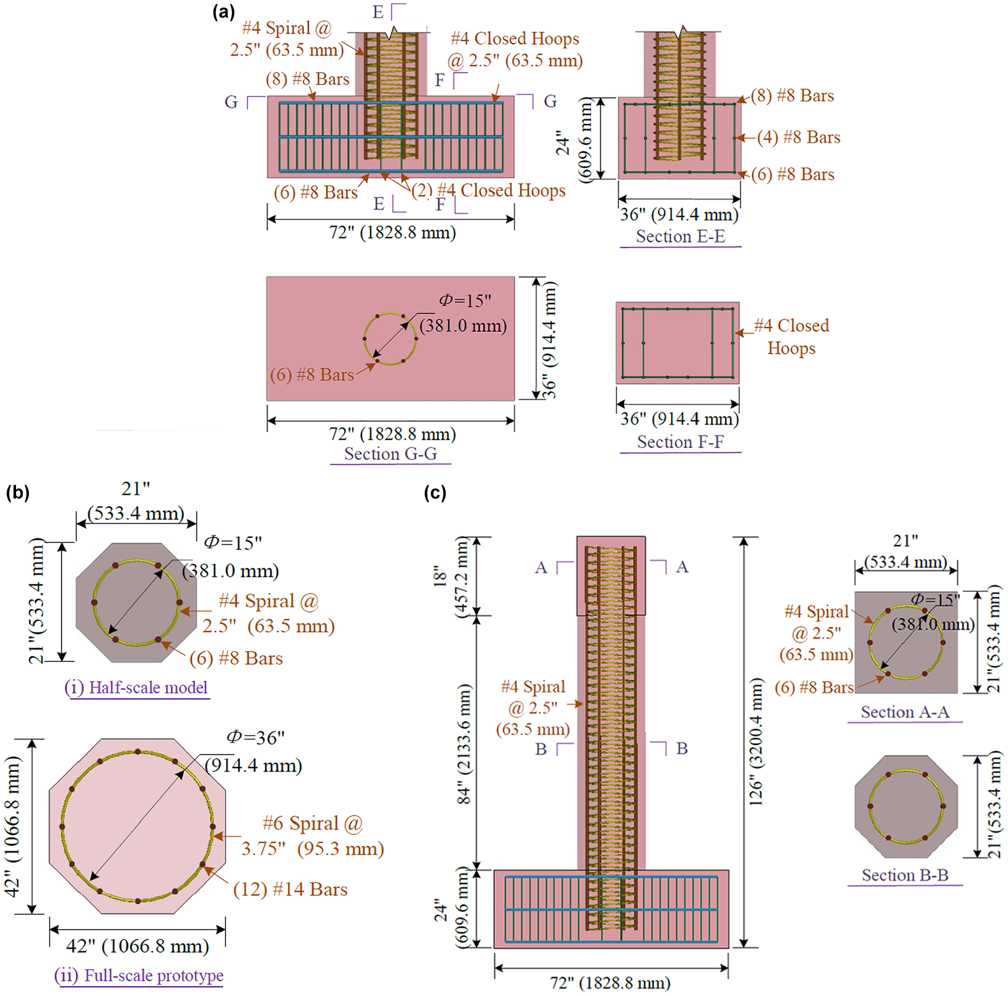
General design details: (a) joint design details of the pier-footing, (b) cross-sections for the conventional columns, and (c) geometry information of the pier.
Modeling Techniques of Half-Scale Piers
General Description of FE Models
In this study, FE models follow the same dimensional scaling, configurations, and applied loads to ensure consistency with Pantelides et al.’s validated approach. Using the software LS-DYNA, a 3D model is developed to validate the structural seismic behavior under cyclic loading scenarios, as depicted in Figure 2. The CIP specimen includes a monolithic concrete construction with two separate rebar cages. The rebar cage within the pier consists of six No. 8 longitudinal bars, each measuring 117.5 in. (2.98 m) in length, and a No. 4 spiral reinforcement with 2.5 in. (63.5 mm) spacing. The rebar cage in the footing contains a total of 18 No. 8 longitudinal bars, enclosed by 22 No. 4 double hoops.
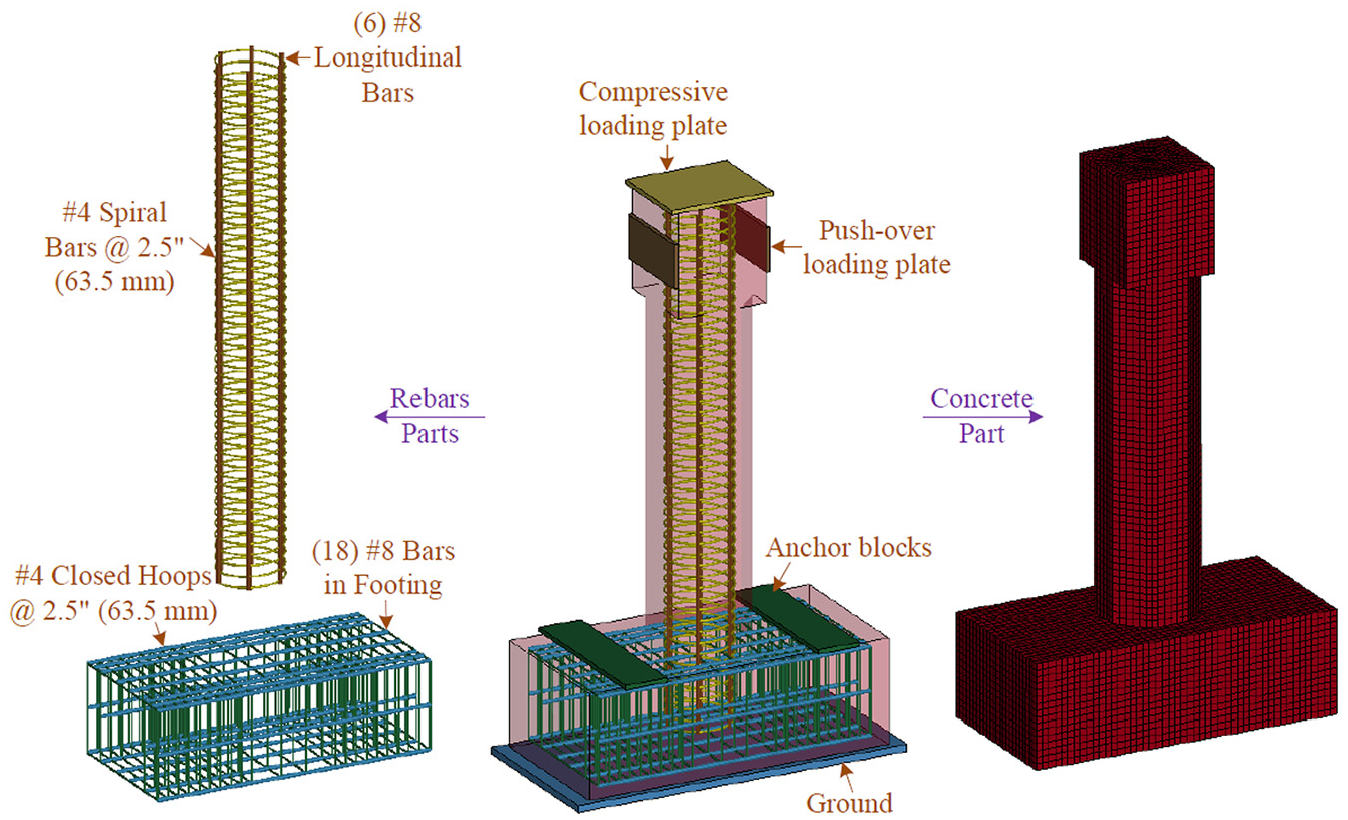
Details of finite element model.
The loading system in the model is simplified, featuring a compressive loading plate located at the top of the pier and two pushover loading plates positioned at the mid-height of the square cross-section part of the pier. The constraint system includes the ground below the bottom of the footing and two anchor blocks positioned on the upper surface of the footing. For simplicity, all steel components in the loading and constraint systems are called “accessory steels” in the following sections.
The concrete and accessory steels are all modeled using SOLID_164 elements, while the reinforcements are modeled with BEAM_161 elements. Mesh size is critical for nonlinear analysis, where a larger mesh may result in an unusual distribution of damage. Drawing on the recommendations from recent research articles, which examined the impact response of concrete structures modeled in LS-DYNA, mesh sizes ranging from 0.39 in. to 1.97 in. (10 mm to 50 mm) were highly recommended ( 8 , 9 , 18–20). A mesh sensitivity analysis conducted in a previous study by the authors guided the selection of the mesh size while also considering computational efficiency ( 21 ). In the model, the average mesh sizes for the concrete and rebars are set to 1 in. (25.4 mm). No bond-slip is considered between the reinforcing steel and the concrete. The model consists of a total of 54,120 elements and 65,888 nodes.
Contact and Boundary Conditions
To replicate the experimental boundary conditions of the specimen, several constraints are applied using the keyword *BOUNDARY_SPC_SET. All nodes at the bottom of the ground and the top of the anchor blocks are fully constrained in three translational degrees of freedom. Additionally, the contact between the anchor blocks and the footing, as well as between the ground and the footing, is defined as fixed. Meanwhile, nodes on both sides of the footing are restrained in the lateral cyclic loading direction (X direction) to replicate the boundary conditions used in seismic experiments ( 11 ). In these experiments, the footing was bolted to the top anchor blocks and the ground to effectively restrict its movement and rotation, ensuring that the specimen remained securely anchored during testing. A similar boundary condition was adopted in previous studies ( 22 – 24 ). Additionally, the top-side nodes of the compressive loading plate are restrained in the X and Y directions while being allowed to move freely in the loading direction (Z direction), as illustrated in Figure 3. The *CONTACT_AUTOMATIC_SURFACE_ TO_SURFACE model is used to model the interactions between the specimens and the compressive and pushover loading plates. The static friction coefficient equals 0.2 and a dynamic friction coefficient equals 0.15 ( 25 ).
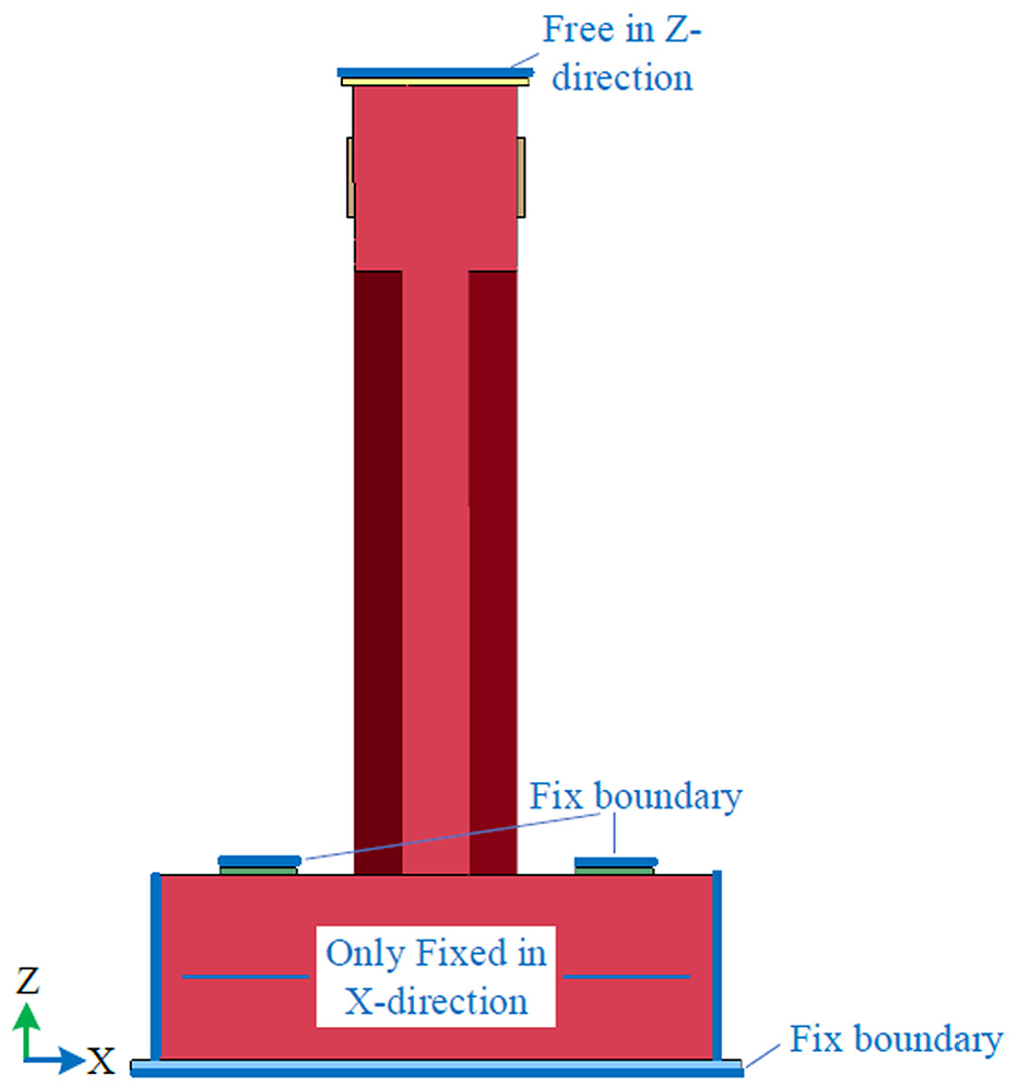
Boundary conditions.
Material Properties
*MAT_CSCM (Continuous Surface Cap Model) is designed to model both elastic deformation and failure of concrete used in roadside safety applications under vehicle impact ( 26 ). It is used in many recent impact simulations, and can predict the concrete mechanical behavior under impact loading ( 27 ). CSCM is a concrete model that combines the shear (failure) surface with the hardening compaction surface (cap) smoothly. This model provides isotropic constitutive models, failure and hardening surfaces, damage-based softening with erosion, and rate effects for high strain rate. Rate effects are an important factor in dynamic behavior of concrete models under impact loading. Rate effects are considered through increasing the fracture energy (Gf), the dynamic fracture energy (Gfdyn) and the dynamic tensile/compression strength (f’dyn ) as shown in Equation 1:

where
E = Young’s modulus,
repow = a user-specified input parameter (defined as the power that increases fracture energy with rate effects, and equals 1) ( 27 ), and
η = the effective fluidity coefficient.
The average compressive strength values used are 6 kips per square inch (0.041 GPa) for concrete, as measured on the test day.
The constitutive relation of the longitudinal bars is described by the kinematic elastic–plastic material model *MAT_PLASTIC_KINEMATIC. The Cowper-Symonds equation is used to describe the dynamic increase factor (DIF) of the structural steel and is shown in Equation 2 ( 28 , 29 ):

where
C = a parameter of the material’s strain rate (equaling 40.5), and
P = a parameter of the material’s strain rate (equaling 5.0).
The accessory steels in the model are assumed rigid, using the *MAT_RIGID material to save the analysis time. Even though this material does not deform under loading, values assigned to the density, Young’s modulus, and Poisson ratio are taken for typical steel material. The specific material parameters utilized in the FE models are detailed in Table 1.
Material Parameters in Finite Element Models
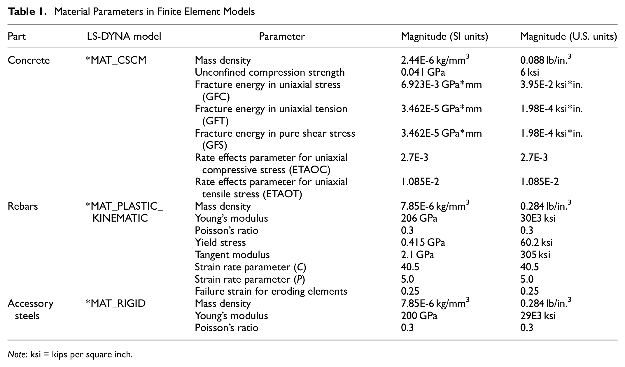
Note: ksi = kips per square inch.
Loading Procedures
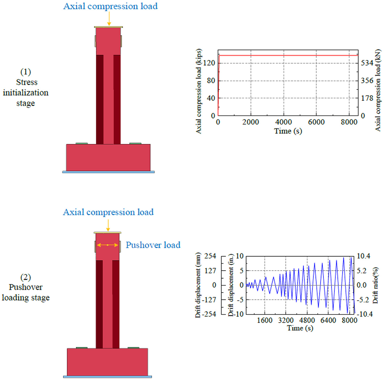
In LS-DYNA, the RESTART analysis mode is utilized to effectively manage the loading sequence following the initialization of gravity and precompression forces. This approach enables the application of cyclic quasi-static loading to study the seismic behavior of the piers, as illustrated in Figure 4. The analysis consists of two stages:
1) Stress initialization stage: To establish the initial stress state, the self-weight of the structure is applied using *LOAD_BODY_Y with an acceleration curve. An axial prestressing load equivalent to 6% of the pier’s axial capacity, amounting to 137.59 kip (612.1 kN), is applied using *LOAD_RIGID_BODY to simulate the typical gravity load in a bridge pier ( 11 ). The axial compression load (6% of the pier’s axial capacity) remains consistent with Pantelides et al. ( 11 ). Once static equilibrium is achieved, the state of the structure is saved for subsequent analysis.
2) Lateral cyclic loading stage: After the stress initialization stage, a pushover loading plate is employed to control displacement using *BOUNDARY_PRESCRIBED_MOTION_RIGID, positioned 8 ft (2.44 m) above the pier base. The cyclic loading protocol applied displacement control, executing two cycles for each drift ratio ranging from 0.5% to 10%. Initially, the displacement rate is 1.2 in./min (30.48 mm/min) until the 3 in. (76.2 mm) of drift ratio. Then the rate is increased to 4 in./min (101.6 mm/min) and maintained through to the end of the test ( 11 ).
Loading stage description.
Verification of Simulated Results
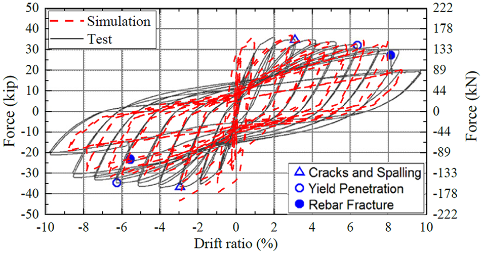
Figure 5 compares the hysteresis curves derived from experimental results of Pantelides et al. with those obtained from this study’s FE analysis ( 11 ). Overall, the hysteresis curves from the experiments and numerical simulations result in similar shapes and trends. Initially, before reaching a 2% drift ratio, the hysteresis loops from the numerical simulation appear fuller than the experimental observations. This discrepancy is primarily because of the more rigid constraints in the FE model, which suggests a greater energy dissipation capability at the beginning of the pushover procedure. As the loading continues and the drift ratio increases, the hysteresis loops from both methods align more closely. Thus, the FE model accurately captures the progressive stiffness degradation and energy dissipation characteristics observed in the experimental tests and the seismic performance of the pier.
Hysteresis curves.
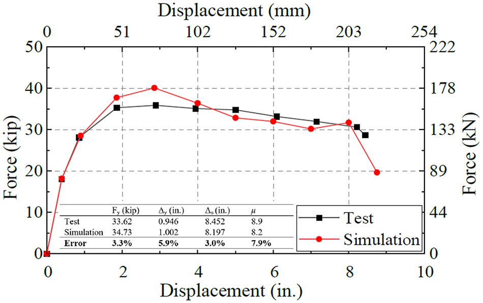
To quantitatively verify the accuracy of the FE modeling compared with experimental results, the average skeleton curves are derived from the hysteresis curves of the FE analysis and experimental data of Pantelides et al. ( 11 ). The average skeleton curve is constructed by averaging the positive and negative peak values of the first cycle for each drift ratio. These skeleton curves represent the backbone of the cyclic response, summarizing the overall load-displacement behavior, and allow for a direct comparison between the numerical simulation and physical test.
By comparing these average skeleton curves, key characteristics are calculated and analyzed, including the effective yield force (Fy), the effective yield displacement (Δ y ), the ultimate displacement (Δ u ), and the displacement ductility capacity (μ). According to ACI 374, it is assumed that the idealized elasto-plastic curve intersects the average backbone curve at a point where the force is 70% of the effective yield force to determine the effective yield displacement (Δ y ) ( 30 ). The ultimate displacement (Δ u ) is defined as the displacement at which there is a 20% reduction in the lateral load capacity. The displacement ductility capacity (μ) is the ratio of the ultimate displacement to the yield displacement (Δ u /Δ y ). These values are summarized in Figure 6. The error in the displacement ductility capacity between the numerical and experimental result is 7.9%, and the error in effective yield force is 3.3%. Overall, the FE method demonstrated a high level of accuracy in capturing the lateral bearing capacity and seismic structural resilience, making it a dependable tool for simulating structural behavior under cyclic loading conditions.
Average skeleton curves.
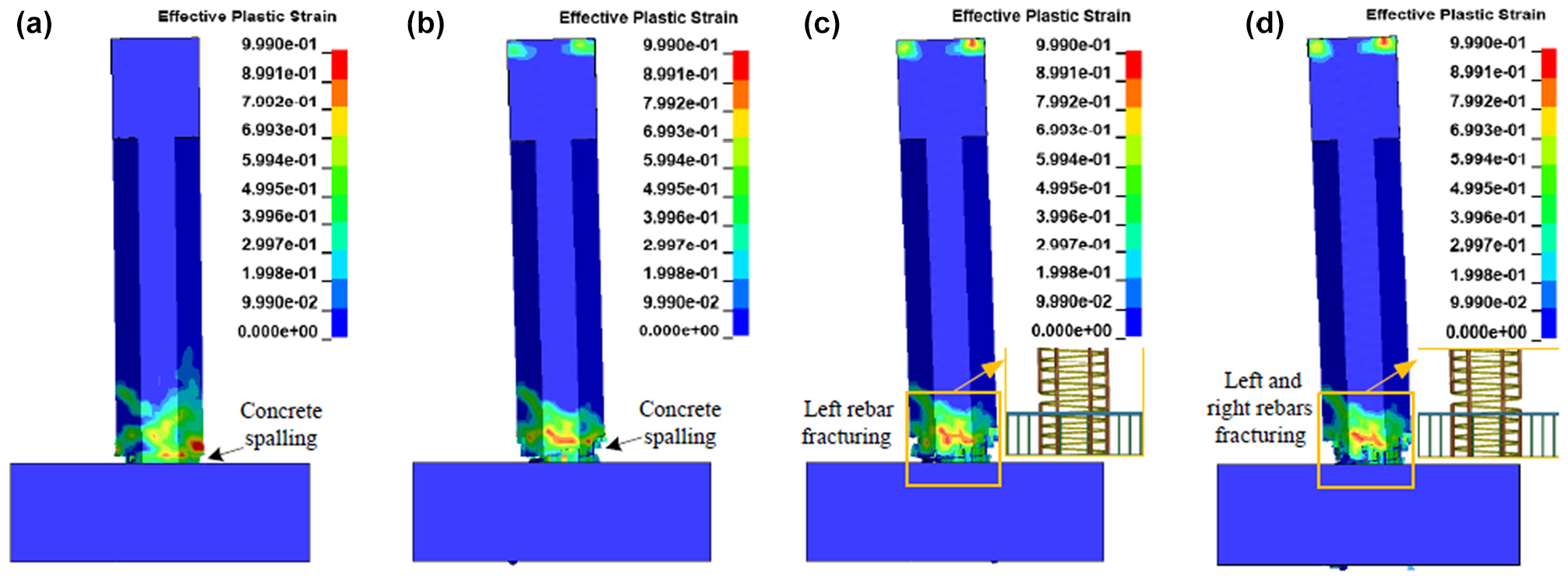
To further understand the crack development process of the specimen in the FE models, effective plastic strain patterns at critical drift ratios are presented in Figure 7. Horizontal cracks initially appear at the pier base. As the drift ratio increases to 3%, spalling began at the pier corners, indicating significant stress concentration and material degradation in these areas. At a 6% drift ratio, the concrete spalls on both corners of the pier in the loading direction propagating upwards. At the 8% drift ratio, the extreme left rebar fractures, followed by the extreme right rebar fracturing above the pier-to-footing interface at the 9% drift ratio. This progression is consistent with the experimental results.
Damage developments: (a) drift ratio = 3%, (b) drift ratio = 6%, (c) drift ratio = 8% and (d) drift ratio = 9%.
In Figure 8, for the CIP specimen, initial concrete spalling is observed at the column corners by the end of the 3% drift ratio. By the 6% drift ratio, the spalling continues to propagate, exposing a 6 in. height of the rebar cage. At the end of the simulation, the two extreme rebars fracture, leading to an 11 in. height of concrete spalling and further exposure of the rebar cage. In summary, the FE models accurately reflect the crack distribution and damage progression observed in the experimental specimens (Figure 4.16 on p. 68 in Pantelides et al.) ( 11 ). They effectively captured key processes such as cracking, crushing, and the development of plastic hinges. These results validate the suitability of the FE analysis method for further study of seismic performance in concrete piers after impact events.
Cast-in-place’s damage states: (a) drift ratio = 3% (cracks and spalling), (b) drift ratio = 6% (spalling and inclined cracks) and (c) at the end of simulation (cracks, spalling, concrete delamination, and fractured rebar).
FE Analysis of RC Pier Under Sequential Impact and Seismic Loads
To explore the residual seismic capacity of RC piers following an impact event, the pier model is subjected to a sequential loading protocol. First, an impact load is applied to simulate damage from an impact event. Following this, a quasi-static cyclic loading is applied to model seismic response and evaluate the pier’s residual capacity.
General Description of FE Models
The pier developed in Calibration Section is utilized. To simulate an impact scenario, an impactor is added at a height of 1 ft 6 in. (457.2 mm) above the bottom of the pier part. In Chen et al., a rigid model vehicle is specifically designed for impact testing and modeling ( 9 ). The impactor represents a model vehicle comprised of a front plate, force transducer, back plate, and vehicle body. The dimensions of the vehicle body are 37.8 × 39.4 × 23.6 in. (960 × 1,000 × 600 mm), while the front and back plates are each 1.6 in. (40.6 mm) thick. The front plate had an arched surface, and the force transducer is a cylinder with a diameter of 10.6 in. (269.2 mm) and a height of 9.6 in. (243.8 mm). The general view of the FE model and dimensions of the impactor are illustrated in Figure 9.
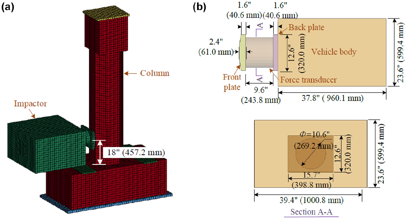
Description of finite element (FE) models: (a) general view of FE impact model and (b) details of impactor.
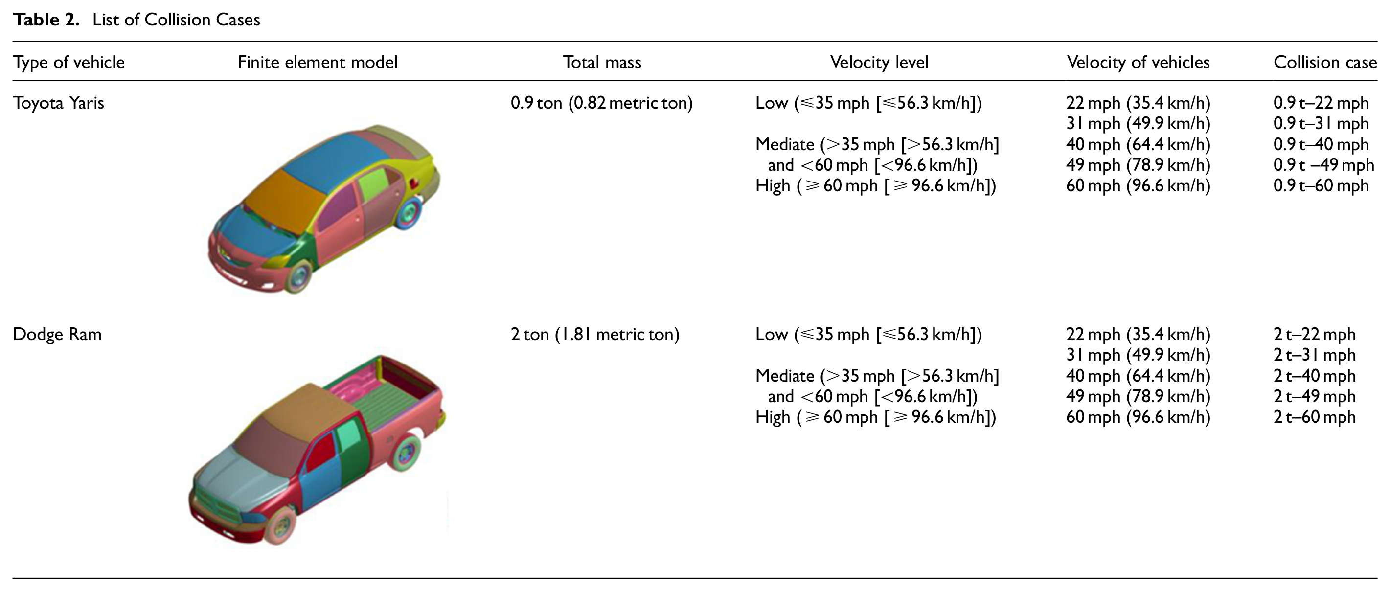
According to the existing literature of vehicle impact, two lightweight vehicles are commonly used for impact studies: a Toyota Yaris passenger car (0.9 ton [0.82 metric ton]), and a Dodge Ram pickup truck (2 ton [1.81 metric ton]). This study examines these vehicles at five different velocity ranges from 22 mph to 60 mph (35.4 km/h to 96.6 km/h). The specific collision scenarios examined are summarized in Table 2. For instance, the case titled “0.9 t–22 mph” indicates an impact scenario where the total mass of the impactor is 0.9 ton (0.82 metric ton), and the impact velocity is 22 mph (35.4 km/h). The impactor is modeled using SOLID_164 elements, with an average mesh size of 1 in. (25.4 mm). It is assumed rigid and utilizes the *MAT_RIGID material model, with two varying densities to represent the specific masses of the impact scenarios. All boundary conditions are consistent with those described in Calibration Section. Additionally, the *CONTACT_AUTOMATIC_SURFACE_TO_SURFACE model is used to describe the interactions between the specimens and the impactor, employing both static and dynamic friction coefficients of 0.3 ( 31 ).
List of Collision Cases
Loading Procedures
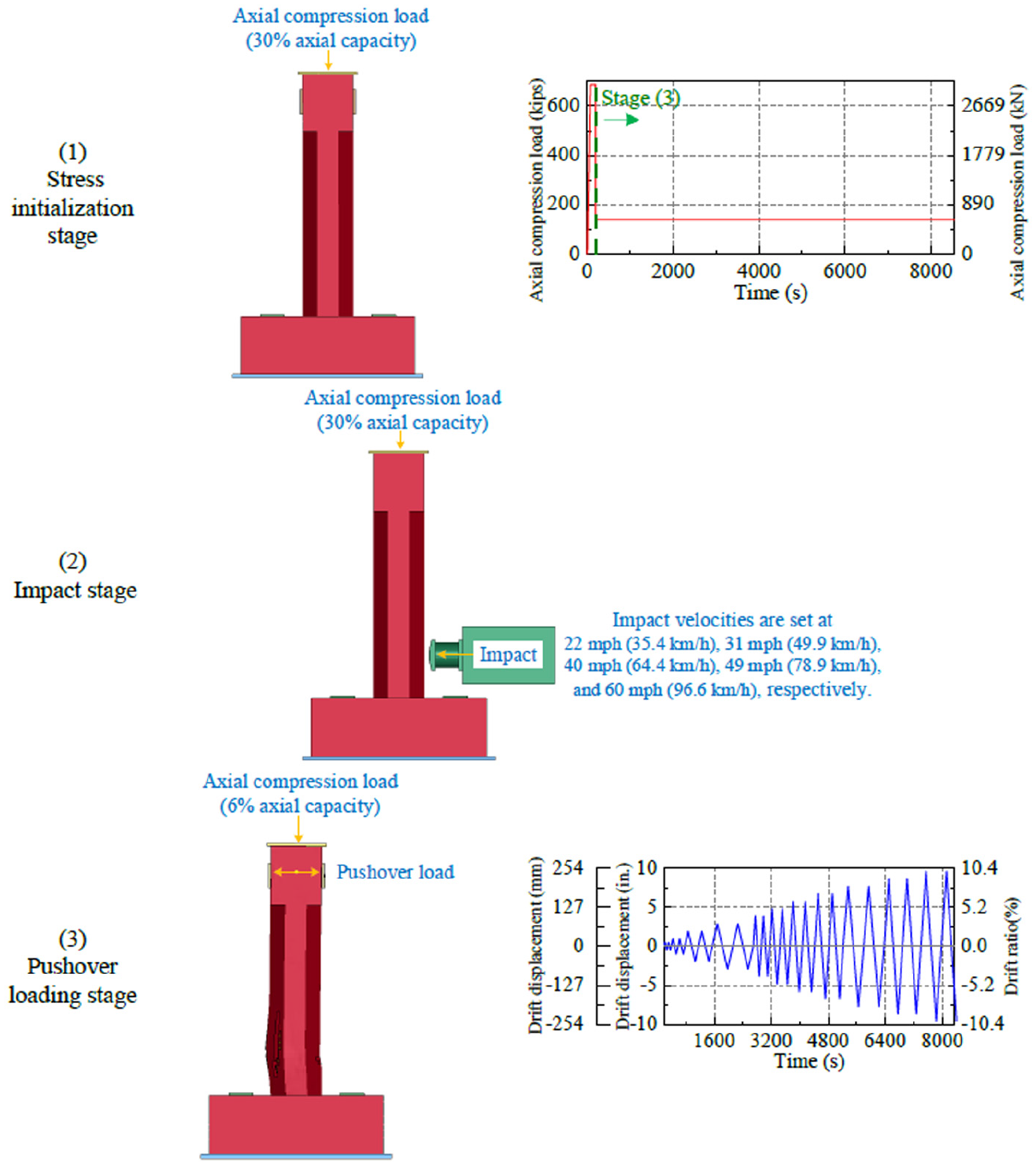
The RESTART function enables the effective execution of loading sequence analysis. To explore the residual seismic capacity of piers following an impact event, as illustrated in Figure 10, the analysis consists of three stages:
1. Stress initialization stage: To establish the initial stress state, the self-weight of the structure is applied using *LOAD_BODY_Y with an acceleration curve. Additionally, an axial prestressing load equivalent to 30% of the pier’s axial capacity (687.95 kip [3,060.6 kN]) is applied using *LOAD_RIGID_BODY to simulate the typical gravity load in a bridge pier ( 32 ). Once static equilibrium is achieved, the state of the structure is saved for subsequent analysis.
2. Impact stage: Following stress initialization, an impactor is added at a height of 1 ft 6 in. (457.2 mm) above the bottom of the pier, with impact velocities set at 22 mph (35.4 km/h), 31 mph (49.9 km/h), 40 mph (64.4 km/h), 49 mph (78.9 km/h), and 60 mph (96.6 km/h). The initial velocity of the impactor is set using *INITIAL_VELOCITY_GENERATION. During this stage, the axial prestressing load remained at 30% of the pier’s axial capacity (687.95 kip [3,060.6 kN]). This value is chosen to ensure consistency with common impact loading conditions ( 32 , 33 ).
3. Lateral cyclic loading stage: After the impact stage, a pushover loading plate is employed to control displacement using *BOUNDARY_PRESCRIBED_MOTION_RIGID, positioned 8 ft (2.44 m) above the pier base. The cyclic loading protocol applied displacement control, executing two cycles for each drift ratio ranging from 0.5% to 10%. Initially, the displacement rate is set at 1.2 in./min (30.5 mm/min) until the 3 in. (76.2 mm) drift ratio is reached, after which the rate is increased to 4 in./min (101.6 mm/min) and maintained at this speed for the remainder of the test. The axial prestressing load is reduced to 6% of the pier’s axial capacity (137.59 kip [612.1 kN]) to remain consistent with Pantelides et al. ( 11 ). This value is also used in the validated model to allow for direct comparison between damaged and undamaged columns under pushover loading.
Loading stage description.
Discussion
After the impact loading phase, the damage distributions at the end of the impact are compared. Displacement curves of the piers at various height levels are generated and compared to quantitatively investigate the structural impact response under different impact velocities. Following this, a quasi-static cyclic loading phase is conducted to observe and compare the damage patterns in these piers at various drift ratio—1%, 2%, and at the point of failure—gaining insights into the damage progression under cyclic loading. Skeleton curves are derived from the FE results to explore the effect of impact on reducing the seismic capacity of piers. The displacement ductility capacity (μ) is calculated and analyzed.
Dynamic Response during Impact
After the impact loading phase, the damage distributions of the piers at the end of the impact loading are summarized by the mass of the impactor and velocity, as shown in Figure 11. As expected, the comparison of each set of damage patterns reveals that an increase in vehicle velocity results in progressively more severe damage to the piers.
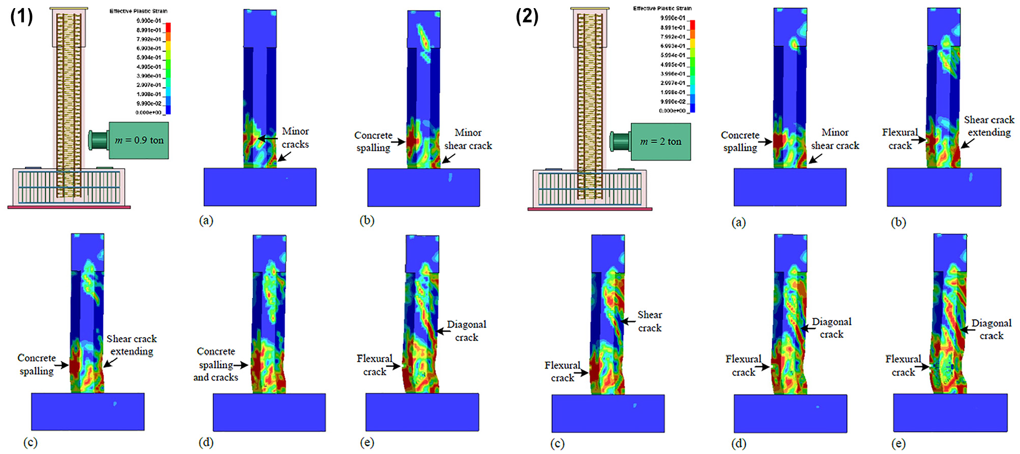
Failure modes under impact loading: (1) The end moment of Toyota Yaris (0.9 ton [0.82 metric ton]) impact: (a) CIP - 0.9 t - 22 mph, (b) CIP - 0.9 t - 31 mph, (c) CIP - 0.9 t - 40 mph, (d) CIP - 0.9 t - 49 mph and (e) CIP - 0.9 t - 60 mph. (2) The end moment of Dodge Ram (2 ton [0.81 metric ton]) impact: (a) CIP - 2 t - 22 mph, (b) CIP - 2 t - 31 mph, (c) CIP - 2 t - 40 mph, (d) CIP - 2 t - 49 mph and (e) CIP - 2 t - 60 mph.
In Figure 11, the first set of results shows the impact of the Toyota Yaris (0.9 ton [0.82 metric ton]) at various velocities. At 22 mph (35.4 km/h), the damage to the CIP pier is relatively minor. At a velocity of 31 mph (49.9 km/h), a single shear crack at a 45-degree angle is observed at the bottom of the pier on the impact surface. Meanwhile, a small area of concrete spalling is noted on the opposite side of the pier, indicating the localized effect of the impact. As the impact velocity increases to 40 mph (64.4 km/h) and 49 mph (78.9 km/h), these local damages spread throughout the pier section. At 60 mph (96.6 km/h), a significant diagonal crack at a 30-degree angle is observed, extending from the impact location to the top of the pier and accompanied by flexural cracks. This is attributed to the combined effects of the bending moment and the large shear force, resulting in a typical punching failure of the CIP pier. In the second set of results, examining the impact of the Dodge Ram (2 ton [1.81 metric ton]) at various velocities, a minor shear crack at a 45-degree angle on the impact surface and an area of concrete spalling on the opposite side are observed at a velocity of 22 mph (35.4 km/h). At 49 mph (78.9 km/h), a significant crack at a 30-degree angle extended from the impact location to the top of the pier. Additionally, more shear cracks are found at the top of the pier on the impact face. Based on these observations, the failure mode of the pier is punching shear failure.
To investigate the structural impact response of piers under different impact velocities, displacement curves of the piers at various height levels at the end moment of the impact are generated and compared, as shown in Figure 12. Under the impact of the Toyota Yaris (0.9 ton [0.82 metric ton]), the maximum displacement for the CIP piers occurred at the impact location, which is 18 in. (457.2 mm) above the pier base. No slip is observed at the footing-pier interface, indicating a strong connection between the footing and pier.
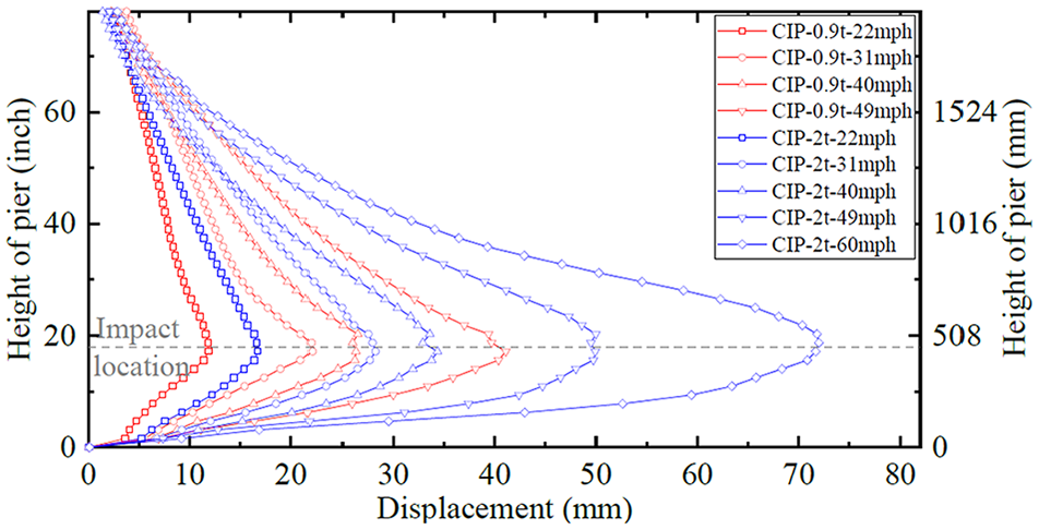
Displacement responses of piers under impact loading.
To further evaluate the residual axial bearing capacity of the post-impact column, a gradually increasing displacement-controlled load is applied at the pier top until failure. The residual axial load-time history curve for the column struck by a Toyota Yaris (0.9 ton [0.82 metric ton]) at a velocity of 22 mph (35.4 km/h) is presented in Figure 13a. At t = 561 s, the axial load of the pier reaches its peak value, which is defined as the residual axial bearing capacity of the pier (P res = 2,175 kip [9,677.6 kN]). The same method is used to determine the residual bearing capacity for the other nine cases. Similarly, for the undamaged pier, a displacement-controlled load is applied at the pier top, and its initial axial bearing capacity (P ini = 2,293 kip [10,198.8 kN]) is extracted.
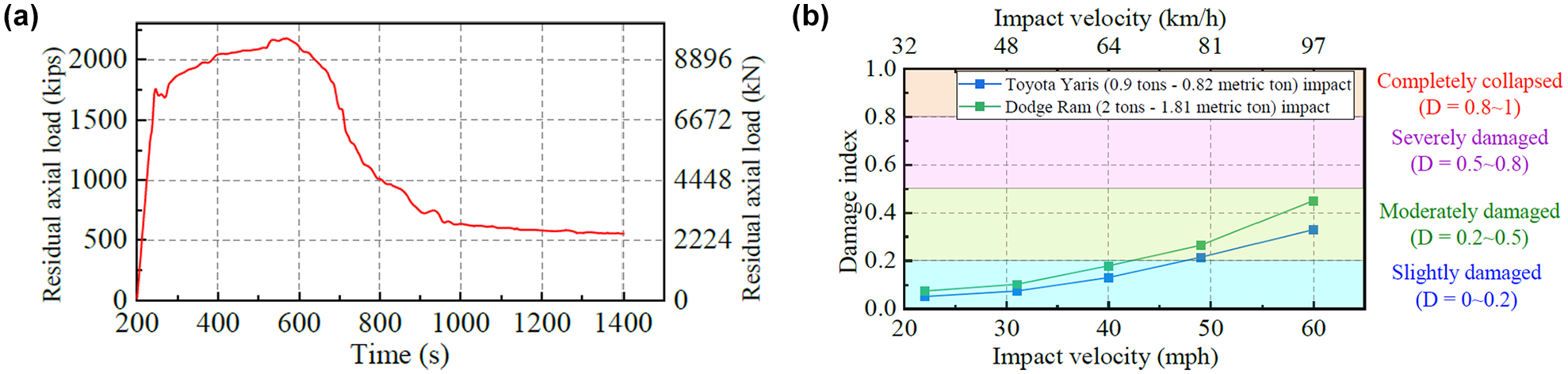
Residual axial capacity of post-impact columns: (a) residual axial load-time history curve for piers (CIP–0.9 t–22 mph) and (b) damage index curves.
Based on the residual axial bearing capacity, the damage index (D) is calculated using Equation 3 ( 34 ):

where
Pres = the residual axial bearing capacity of the pier after the impact, and
Pini = its initial axial bearing capacity.
The damage indices (D) corresponding to different impact conditions are computed and illustrated through the curves in Figure 13b. The damage level classification of the indices D in the figure is referenced from Zhang et al. ( 34 ).
In Figure 13b, the damage index (D) increases as the impact velocity rises. Across all examined impact cases, the damage index remains within the slightly damaged category (D = 0–0.2) when the impact velocity is 40 mph (64 km/h) or lower for both vehicle types. However, when the impact velocity exceeds 40 mph (64 km/h), the damage index transitions into the moderately damaged category (D = 0.2–0.5). It suggests that, although the piers experience some degree of structural degradation, they still retain a significant portion of their axial-bearing capacity (≥50%) post-impact.
Residual Seismic Capacity Assessment of Post-Impact Stage
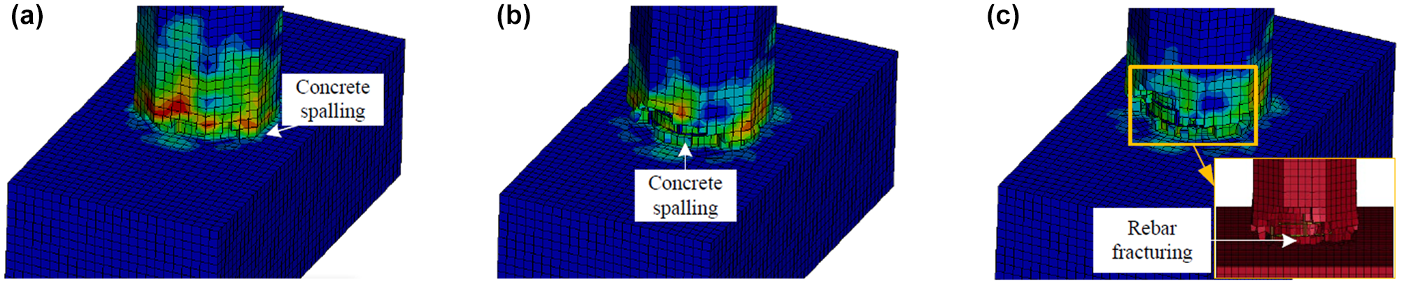
To gain insights into the damage progression of post-impact piers under cyclic loading, the Dodge Ram (2 ton [1.81 metric ton]) at a velocity of 22 mph (35.4 km/h), is selected for detailed analysis and comparison. Figure 14 provides a comprehensive summary of the damage distribution observed in the pier at various drift ratios: 1%, 2%, and at the point of failure. For the piers, a significant amount of concrete spalling is observed at the impact level on the side opposite the impact at a 1% drift ratio. At a 2% drift ratio, the concrete continues to spall upwards, and a shear crack developes at the pier base. This damage pattern is notably different from that of undamaged piers, which typically exhibit concrete failure only at the pier base corners in the pushover direction. In the post-impact piers, the shear cracks and concrete spalling persist, indicating that these weakened areas are prone to early failure under cyclic loading. Once the cyclic load is applied, these pre-damaged regions are the first to exhibit failure. At a drift ratio of 3%, the pier collapses, primarily because of the shear crack at the base.
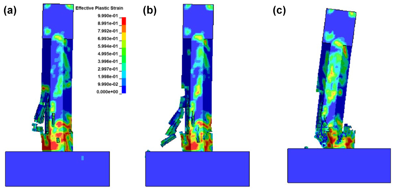
Damage development progressions of piers (CIP–2 t–22 mph): (a) drift ratio = 1%, (b) drift ratio = 2% and (c) drift ratio = 3%.
To explore the effect of impact on reducing the seismic capacity of piers, skeleton curves are derived from the FE results. Figure 15 shows and compares these curves, providing a detailed analysis of how the impact influences the structural performance and residual seismic capacity of the piers. A comparison between Figure 15, a and b , demonstrates that higher impact velocities and heavier impact masses significantly reduce the drift ratio at failure. This reduction in failure drift ratio indicates that piers subjected to more severe impacts have a diminished ability to exhibit ductile performance during seismic events, resulting in lower seismic capacity.
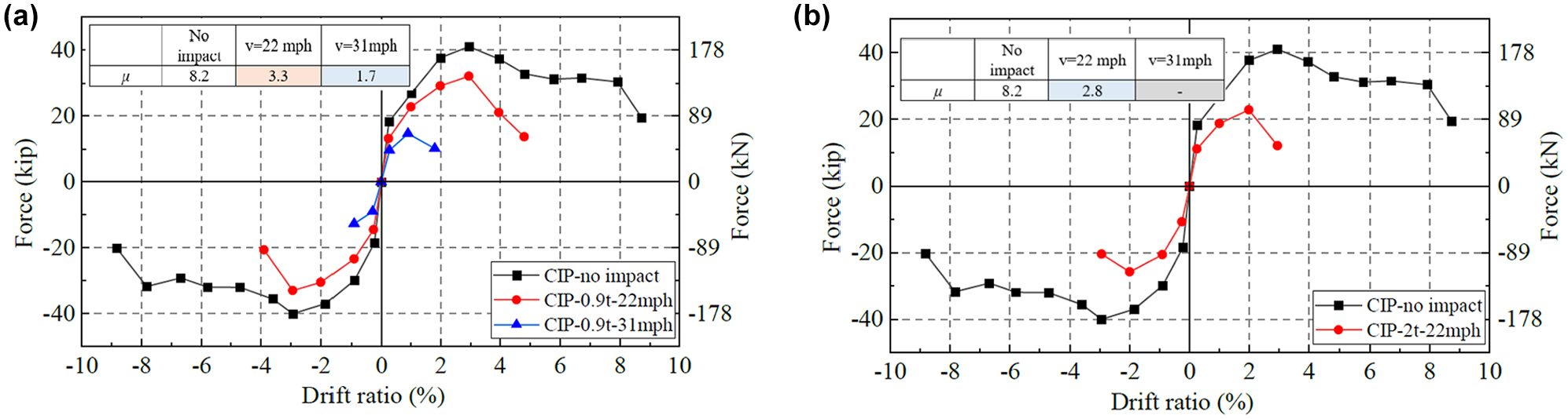
Post-impact skeleton curves and their displacement ductility capacities: (a) CIP–0.9 t and (b) CIP–2 t.
Additionally, the displacement ductility capacity (μ) is calculated and analyzed. The calculation method for displacement ductility capacity is introduced in Calibration Section. According to the Caltrans SDC, the minimum displacement ductility capacity for ductile components is 3.0 ( 35 ). Furthermore, the American Association of State Highway and Transportation Officials (AASHTO) Guide Specifications for Load and Resistance Factor Design (LRFD) Seismic Bridge Design specify that the local ductility demand for ductile members in high-seismic zones is limited to 5.0 for single-pier bents and 6.0 for multiple-pier bents ( 1 ). Based on the simulation results, a vehicle weighing less than 0.9 ton (0.82 metric ton) and colliding with a pier at a velocity less than 22 mph (35.4 km/h) achieves a displacement ductility capacity of 3.3. This indicates that, under these conditions, the pier would not pose a threat to the bridge’s structural integrity in a subsequent earthquake, according to SDC standards. However, exceeding these impact conditions may compromise the structural integrity of the piers and their ability to withstand future seismic events. For instance, a post-impact pier subjected to a collision with a 0.9 ton (0.82 metric ton) vehicle at 31 mph (49.9 km/h) shows a reduction in displacement ductility capacity from 8.2 (for an undamaged pier without impact) to 1.7. Similarly, a collision with a 2 ton (1.81 metric ton) vehicle at 22 mph (35.4 km/h) reduces the displacement ductility capacity to 2.8. Both of these fail to meet SDC requirements. Moreover, none of the post-impact piers satisfy the AASHTO provisions. It is important to note that the piers in this study are half-scale models while the vehicles are full-scale, which may affect the results. Despite this, the findings provide valuable reference points for further investigations into multi-hazard research and the impact of vehicle collisions on the seismic performance of bridge piers.
Plastic rotational capacity is a key characteristic in seismic design. Figure 16 compares the rotational characteristics between an undamaged column and post-impact columns. Plastic rotational capacity is represented by plastic rotation (θp) versus bending moment (M) plots. The bending moment (M) is calculated as the product of the actuator force and the moment arm (8 ft [2.44 m]). Plastic rotation (θp) is determined by dividing the plastic displacement (Δ p ) by the column height (8 ft [2.44 m]). Plastic displacement (Δ p ) is calculated as the difference between the displacement at the actuator level (Δ) and the yield displacement (Δ y ).
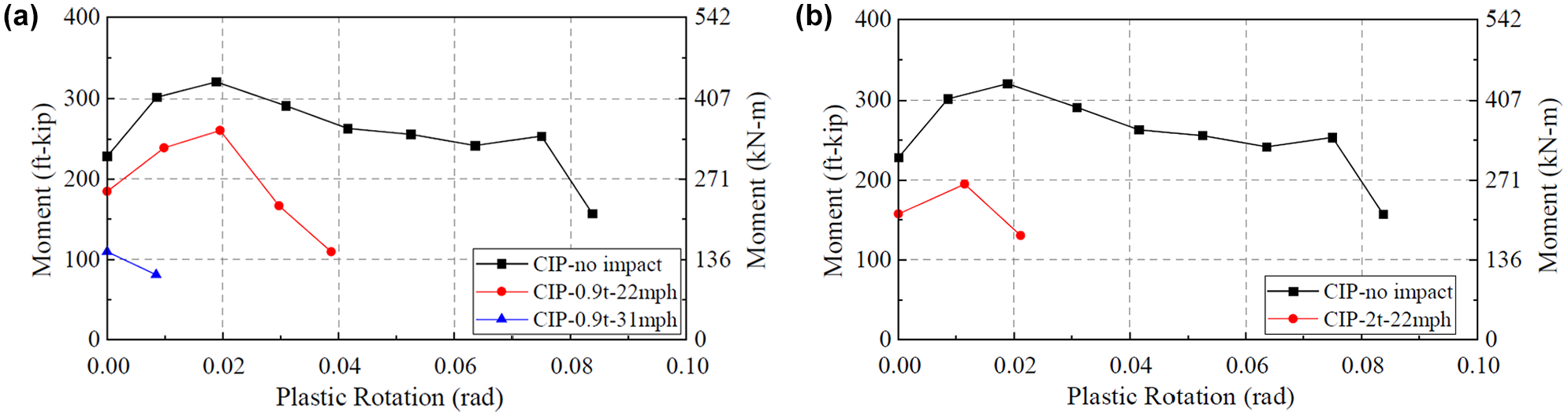
Post impact plastic rotation capacity: (a) CIP–0.9 t and (b) CIP–2 t.
In Figure 16, the undamaged column achieves a plastic rotation of 0.0749 rad at an 8% drift ratio before experiencing a significant reduction in moment capacity. In contrast, the post-impact columns show a considerable decrease in moment capacity compared with the undamaged column, reaching their maximum moment capacity at much smaller plastic rotations.
To study the curvature distribution within the plastic hinge region, 10 sensor points are placed along both extreme sides of the column just above the footing, at intervals of 1 in. (25.4 mm), 6 in. (152.4 mm), 6 in. (152.4 mm), 8 in. (203.2 mm), and 8 in. (203.2 mm). For each pair of consecutive sensor points, the differential of displacement in the Z-direction is calculated, representing the difference in displacement between the impact-facing side and the side opposite the impact, referred to as Δz. The curvature ϕ for each segment is then computed by dividing Δz by the product of the vertical distance between the sensors Δh and the segment width (21 in. [533.4 mm]). The average curvature values are normalized by the segment width (21 in. [533.4 mm]).
Figure 17 compares different post-impact columns with the undamaged column to explore how damage affects the column’s rotation capacity in the plastic hinge region. As expected for an undamaged concrete column, a well-distributed curvature profile results, as shown in Figure 17a. Curvature values are highest in the first segment near the column-to-footing interface and gradually decrease with distance from the column base. This distribution is desirable within the plastic hinge region of the column. In Figure 17, b–d , for the post-impact columns, the curvature values are highest around the heights of 13 in. (330 mm) and 21 in. (533 mm), which are close to the impact height of 18 in. (457 mm). The impact causes localized damage and deformation near the impact zone, increasing curvature in this area. Unlike the undamaged column, curvature is concentrated near the base.
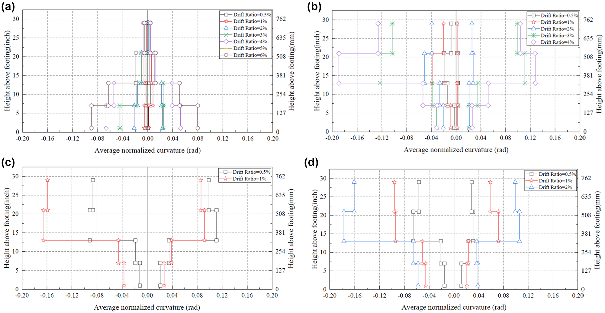
Column curvature profile: (a) CIP–no impact, (b) CIP–0.9 t–22 mph, (c) CIP–0.9 t–31 mph, and (d) CIP–2 t–22 mph.
Potential Repair and Retrofit Strategies
The post-impact seismic capacity of RC columns is significantly reduced, highlighting the need for effective repair strategies and damage detection methods to ensure structural resilience and long-term performance. A key knowledge gap concerns what strategies of repair would restore the columns to an adequate performance level. To address this, several studies proposed various repair and retrofit techniques, including: fiber-reinforced polymer (FRP) strengthening, hybrid jacketing, and carbon-fiber-reinforced polymer (CFRP) wrapping. Parvin introduced FRP strengthening techniques for bridge columns, including FRP strips, sheets, and plates, FRP spraying, and FRP prestressing ( 36 ). Fakharifar et al. proposed hybrid jacketing for rapid repair bridge columns, incorporating grout restoration, sheet metal wrapping, and prestressing strands to effectively restore structural behavior ( 37 ). Zhou et al. demonstrated the effectiveness of CFRP wrapping for circular bridge piers under lateral impact ( 38 ). Cao et al. proposed a CFRP grid and sprayed engineered cementitious composite reinforcement layer for repairing and strengthening seismic-damaged RC concrete columns, demonstrating its effectiveness through experimental testing and FE analysis of five specimen columns ( 39 ). Cheng et al. conducted an experimental and theoretical study on the crushing behavior and energy-absorbing capacity of three types of steel-GFRP-foam sandwich structure, validating their energy-absorbing efficiency ( 40 ). Collectively, these repair techniques provided a foundation for exploring optimal repair strategies to ensure resilience.
Instead of rapid repair strategies, damage detection is also critical in preventing further deterioration and ensuring the structural safety of bridge piers after impact events. Zhou et al. synthesized 251 datasets of various vehicle-bridge collision scenarios to train and test six supervised machine learning models, enabling the prediction of post-impact damage states of RC bridge piers subjected to vehicle collisions ( 41 ). Li et al. proposed an automatic damage detection method, which can be exploited for real-time health monitoring of bridges, improving early detection and response to structural damage ( 42 ). Zhang et al. developed a rope-driven bridge pier damage detection robot, incorporating dynamic and stability analysis to enhance automated inspection and damage assessment for bridge structures ( 43 ). By integrating advanced repair techniques with real-time damage detection technologies, future bridge resilience strategies can be significantly enhanced, ensuring timely assessment, targeted repairs, and improved structural safety after vehicle impact events.
Conclusions
This paper outlines the modeling techniques used to simulate the seismic behavior of RC piers and validates the FE models against experimental results. Then, the calibrated model was employed to evaluate the residual seismic capacity following an impact event, using sequential impact and quasi-static cyclic loading. The four main conclusions of this study are:
1) The FE models of half-scale piers show good agreement with experimental results in pushover stages, confirming their accuracy and reliability. Errors in displacement ductility capacity is 7.9%, and errors in effective yield force is 3.3%, demonstrating the accuracy of the FE method. The models effectively capture cracking, crushing, and plastic hinge development, validating their use for further studies on seismic performance in concrete piers.
2) After impact loading, the CIP piers fail in punching shear with a significant 30-degree crack from the impact location to the pier’s top. The maximum displacements for the CIP piers occurr at the impact location, 18 in. (457.2 mm) above the pier base.
3) During the cyclic loading phase, post-impact piers exhibit distinct damage patterns compared with undamaged piers. Shear cracks and concrete spalling from the impact lead to early failure under cyclic loading. CIP piers can withstand impacts from vehicles under 0.9 ton (0.82 metric ton) at up to 22 mph (35.4 km/h) with SDC requirements. However, higher impacts compromise structural integrity. A 0.9 ton (0.82 metric ton) vehicle at 31 mph (49.9 km/h) reduces the ductility capacity from 8.2 to 1.7, and a 2 ton (1.81 metric ton) vehicle at 22 mph (35.4 km/h) reduces it to 2.8. Both cases fail to satisfy SDC and AASHTO standards. These findings highlight the need for reassessment and repair strategies for bridge piers affected by even lightweight vehicle impacts, as seemingly minor collisions can significantly reduce structural ductility. Additionally, design provisions may require updates to account for post-impact performance, ensuring sufficient residual capacity in bridge piers subjected to vehicular collisions.
4) In curvature distribution of columns, curvature peaks of post-impact columns average 13 in. (330 mm) and 21 in. (533 mm). Unlike the undamaged column, where curvature is concentrated near the base, the post-impact curvature profile indicates a shift in plastic deformation toward the impact location.
Future research should explore several key areas including:
1) Future studies should investigate the specific effects of different vehicle shapes and weights on RC piers to improve the accuracy of impact modeling. Additionally, the influence of different pier geometries and the effects of material aging should be examined to assess how structural variations impact resistance to impact, post-impact performance, and seismic behavior.
2) Future research should investigate a scaling methodology for seismic and impact behaviors of bridge piers at different scales and examine the limitations of the half-scale model in accurately simulating the behavior of a full-size bridge column.
3) Future research should develop FE models to simulate the structural performance of repaired piers under both normal service loads and seismic loading. Additionally, further exploration of specific restoration schemes is needed to assess their effectiveness in restoring seismic resilience and ensuring long-term structural integrity.
Footnotes
Author Contributions
The authors confirm contribution to the paper as follows: study conception and design: J. Jiang, A. Sorensen; data collection: J. Jiang; analysis and interpretation of results: J. Jiang; draft manuscript preparation: J. Jiang, A. Sorensen. All authors reviewed the results and approved the final version of the manuscript.
Declaration of Conflicting Interests
The author(s) declared no potential conflicts of interest with respect to the research, authorship, and/or publication of this article.
Funding
The author(s) disclosed receipt of the following financial support for the research, authorship, and/or publication of this article: The authors would like to acknowledge the Mountain-Plains Consortium (MPC)-University Transportation Center sponsored by the U.S. Department of Transportation for providing the research funding (Grant No. 69A3551747108) to support this study.
Data Accessibility Statement
Data will be made available on request.