
Abstract
To achieve underactuated control, a novel swashplateless rotor configuration of asymmetric inclined hinges which can be driven by periodic sinusoidal torque is studied, hopefully eliminating the conventional swashplate mechanism and multiple actuators. Therefore, the traditional mechanism can be intelligently replaced by software. However, high-frequency torque variation will invariably result in vibration noise and energy loss.Thus it is critical to properly design the swashplateless rotor in order to achieve a control process with less torque variation. As a result, in both numerical simulation and experiments, we performed sensitivity analyses on related design parameters such as hinge eccentricity, hinge inclined angle, and wingtip hammer position. The parameter effect on swashplateless rotor control was discovered through the analyses, and the basic law of its design was obtained.
Introduction
Because of their unique flexibility, micro unmanned aerial vehicles are widely used in a variety of scenarios. The rotor-type UAV, which is the most commonly used, has the characteristics of hovering and easy deployment. UAVs have grown in popularity in recent decades due to their miniaturization. They will be more convenient and safer if they are smaller and lighter. Miniaturization of UAVs in recent years has been primarily due to increased battery power density, as well as miniaturization of electrical components and MEMS sensors. However, the complexity of the aircraft system remains, particularly the mechanical structure, which has become a major impediment to further miniaturization. The sophisticated power system and control structure of unmanned helicopters or coaxial rotor drones take up a substantial portion of the drone’s space and mass, making lightweight and miniaturization extremely difficult. For example, the classic cyclic pitch system of a helicopter, as shown in Figure 1, consists of three servos and a swashplate, among other components. It has been discovered that the standard cyclic pitch control system is so sophisticated that downsizing is difficult. As a result, how to reduce the quality and size of such micro UAVs’ power system and control structures is critical for their further reduction.

The traditional cyclic pith control system.
In a patent issued by Keyence Corporation 1 in 1992, a scheme was proposed to adjust the periodic variation of motor torque in order to control the periodic variation of rotor pitch. This scheme makes use of the elastic connecting rod and the rotor’s aerodynamic resistance to cause the propeller to make periodic pitch adjustments in response to the periodic variation of the motor torque. It does, however, have a mechanism similar to the swashplate, and the inventor only discussed its basic idea in principle, without modeling or experimentation. Reich submitted a patent 2 in 2005 that described an inclined articulated rotor that achieved cyclic pitch control with torque modulation, thereby eliminating the extra driving component. The basic construction is shown in Figure 2. Yet, it was merely at the conceptual stage.
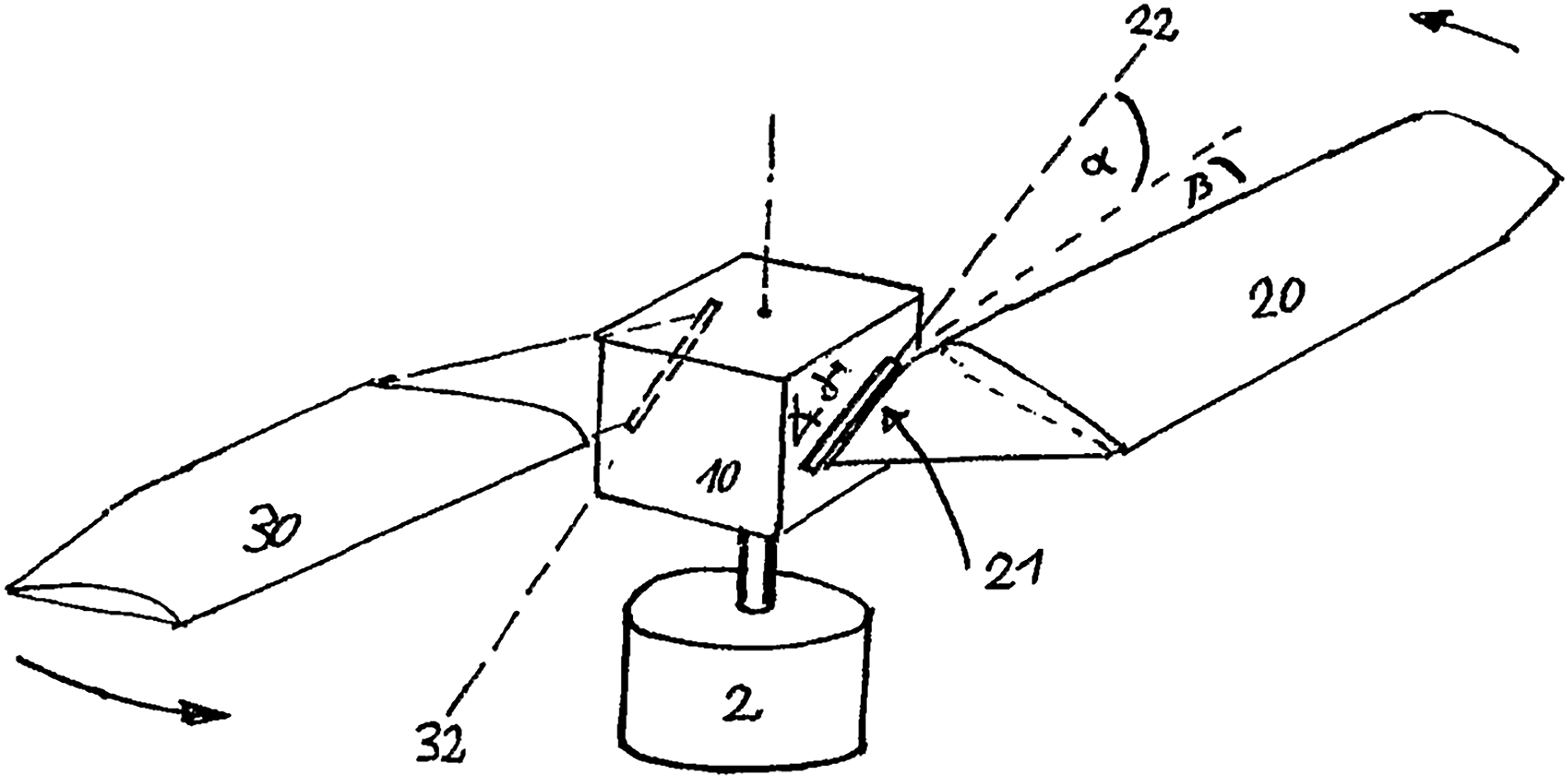
The patent of Reich. 2
Since 2013, Paulos and Yim from Modlab at the University of Pennsylvania have conducted extensive research on swashplateless rotor and proposed a novel swashplateless rotor.3–8 The basic principle of their novel swashplateless rotor is consistent with Reich’s patent. But in Modlab’s design, the plane of inclined hinges is parallel to the vertical plane, and the flap hinge structure was introduced. This design is more reasonable in terms of aerodynamics and structure. Figure 3 depicts the structure of this swashplatelessless rotor. It contains a hub, inclined hinges(lag-pitch hinges), flap hinges, blade grips and blades. Theoretical modelling investigation and experimental verification3–8 of the swashplateless rotor were carried out by Paulos. The theoretical analyses and experiments demonstrated a good application of the swashplateless rotor, which provides a new idea for the future development of the micro unmanned helicopter. In 2019, Yu Jin 9 refined the nonlinear dynamic model of the swashplateless rotor, which took the effect of pitch motion into consideration. Meanwhile, he further conducted analyses of its mechanical stability, dynamic responses and hover stability with his nonlinear model.
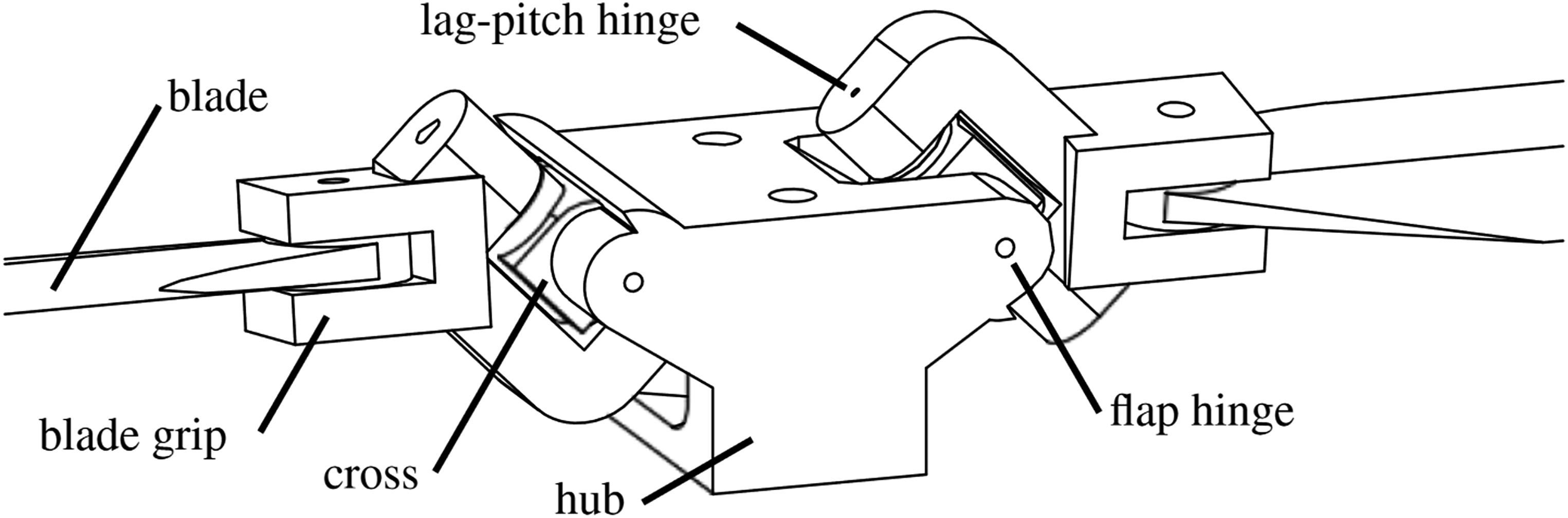
A novel swashplateless structure from Modlab. 5
However, the above investigations focused on dynamic modeling and application. They didn’t care about the parameter effect on the swashplateless rotor control, which could be important to its design. For example, high-frequency torque variation will inevitably cause vibration noise and energy loss in motors, as well as mechanical loss in mechanical structures like the inclined hinge. Furthermore, for the measurement of UAV motion, the motor’s vibration noise should be as low as possible. As a result, a more reasonable hinge structure is required to achieve the same control effect with the least torque variation possible, which obviously makes sense for micro UAVs. Therefore, the following works were completed as part of this study: 1. Simulation is used to investigate the basic design parameters of the swashplateless rotor; 2. The wingtip hammer structure is introduced, and a dynamic model for simulation is established; 3. The test platform and prototype of the swashplateless rotor are constructed, and the theoretical analysis results are experimentally validated.
The remainder of this paper is organized as follows: The working principle and model establishment of a swashplateless rotor are described in the second section. The third section describes the composition and implementation details of experimental prototype. The fourth section contains simulation and experimental analyses. Finally, the fifth section concludes this article.
Basic principle and modeling
Basic principle
As depicted in the Figure 4, the inclined hinges are asymmetric with respect to the motor spindle. The positive blade is the one with the inclined hinge closest to the main shaft of the rotor, and the negative blade is the one with the inclined hinge farthest away from the main shaft of the rotor.

Definition of blades 3 .
As shown in Figure 5 the pitch angle of the positive blade increases as the blade swings backwards around the inclined hinge. When the positive blade swings forward around the inclined hinge, it decreases. The pitch angle of the negative blade decreases when the negative blade swings backwards around the inclined hinge, and increases when the negative blade swings forward around the inclined hinge.The inclined hinge is also known as a lag-pitch hinge due to its characteristics of coupling lag angle and pitch angle motion of the blade. As previously stated, the motion characteristics of the positive and negative blades are diametrically opposed. The angle of attack of the blade will change correspondingly when the driving moment of the rotor changes as a sinusoidal curve in rotation. Because the motions of the positive and negative blades are opposite, the effective moment is formed. The torque produced by cyclic pitch variation can control the pitch and roll of an aircraft, allowing for UAV underactuated control.
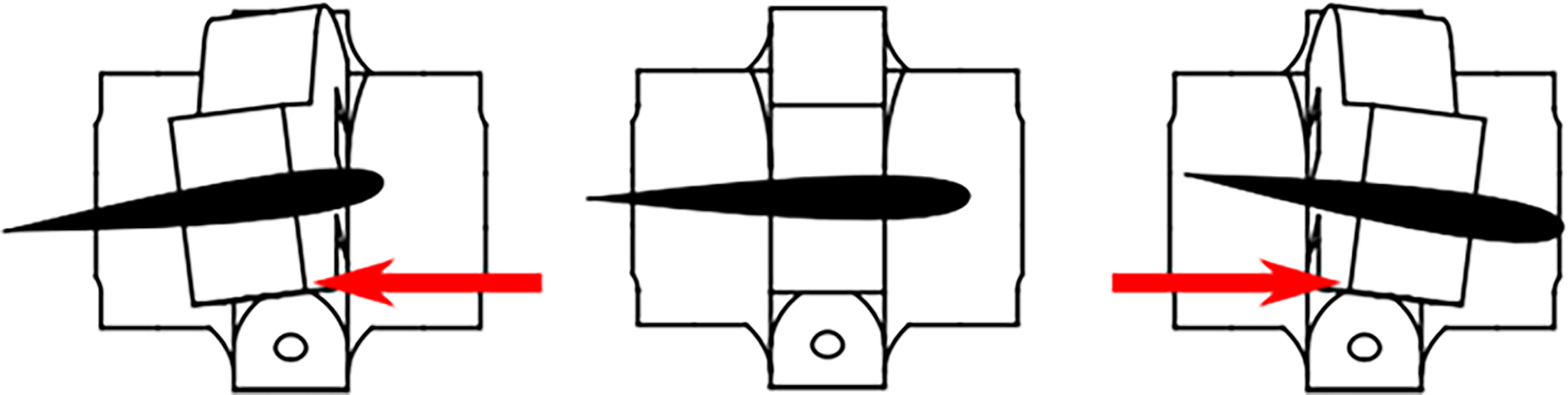
Basic principle of swashplateless. 4
Modeling
The body coordinate system of the rotor is depicted in Figure 6. An inclined angle is defined as the acute angle formed by the inclined hinge and rotor spindle, represented by

The kinematics description of swashplateless rotor. 5
According to the above definition, the pitch angle of the blade, lag angle, and inclined angle have the following kinematic relationship (1) for the positive blade:


The schematic diagram of wingtip hummer.
The radial wingtip hammer moments about the rotor shaft are as follows:
the inertial moment due to hub lead-lag motion: the inertial moment due to blade lead-lag motion: the Coriolis moment due to blade lag motion: the Coriolis moment due to blade flap motion: the inertial moment due to flap motion: the Coriolis moment due to oscillation of rotor shaft rotation speed: the Coriolis moment due to blade lag motion: the centrifugal moment: the inertial moment due to hub lead-lag motion: the inertial moment due to blade lag motion: the Coriolis moment due to oscillation of rotor shaft rotation speed: the Coriolis moment due to blade flap motion: the centrifugal moment due to blade lag angel:
The moments acting on the wingtip hammer about the flap hinge are as follows:
The moments acting on the wingtip hammer about inclined hinge axis are as follows:
Finally, nonlinear high-order small quantity terms are ignored in the model:


Composition of experimental prototype
The basic framework of the swashplateless rotor prototype, as shown in Figure 8, is designed based on the characteristics of the swashplateless rotor. It is divided into the following major components: 1. a Hall magnetic encoder; 2. a brushless motor; 3. a swashplateless rotor 4. a electronic speed controller(ESC); and 5. a control board.

The experimental prototype.
In our prototype, we used the SunnySky V2806-27 Kv650 brushless motor and the T-motor F35A electronic speed controller. The Dshot600 protocol is used by the electronic speed controller. The control command can be updated to over 10 KHz, allowing for rapid adjustment of the motor torque. The AS5048A magnetic encoder is used to determine the position of the rotor. The sampling frequency of it is 11.25 KHz which is high enough. We used the Arduino UNO as the control board, which is simple to program. The blades are taken from the weili model’s K130 main rotor. The rotor’s design is heavily influenced by Paulos’ work. 7 Finally, the basic experimental prototype depicted in Figure 8 was constructed to carry out experiments demonstrated in the next section.
Control sensitivity analysis
The steps depicted in Figure 9 are taken to solve the swashplateless rotor dynamics model. The amplitude of lag angle and flap angle of the blade (
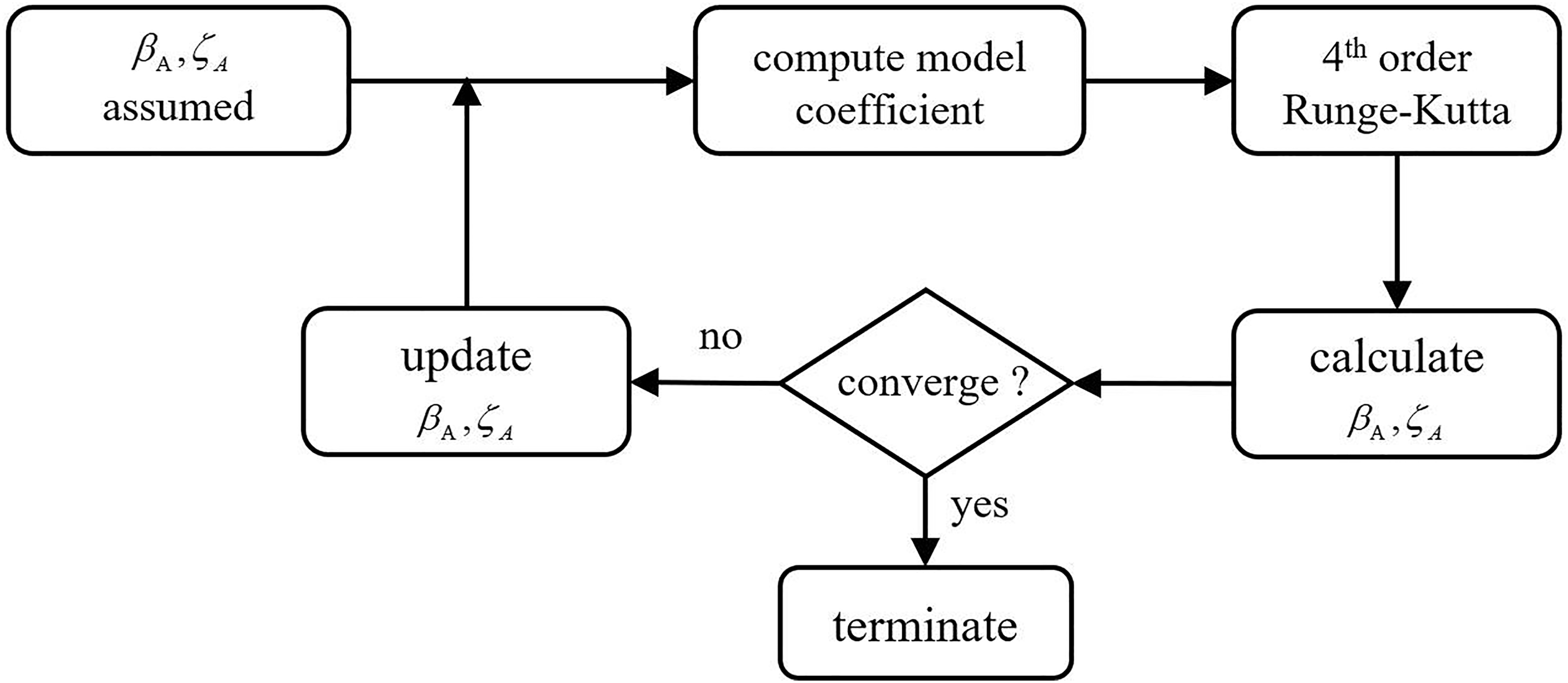
Swashplateless rotor dynamics model solved with numerical method.
Except for the parameter that needed to be changed, all of the parameters in the simulations are the same as in the reference. 6 Compared to the experimental data and simulation data of reference, 6 Figures 10 and 11 show that the simulation framework of the swashplateless rotor model established in this paper can accurately predict the motion characteristics of the swashplateless rotor, which can provide the foundation for design parameter analyses in the following part.

Lag angle response with sinusoidal torque.
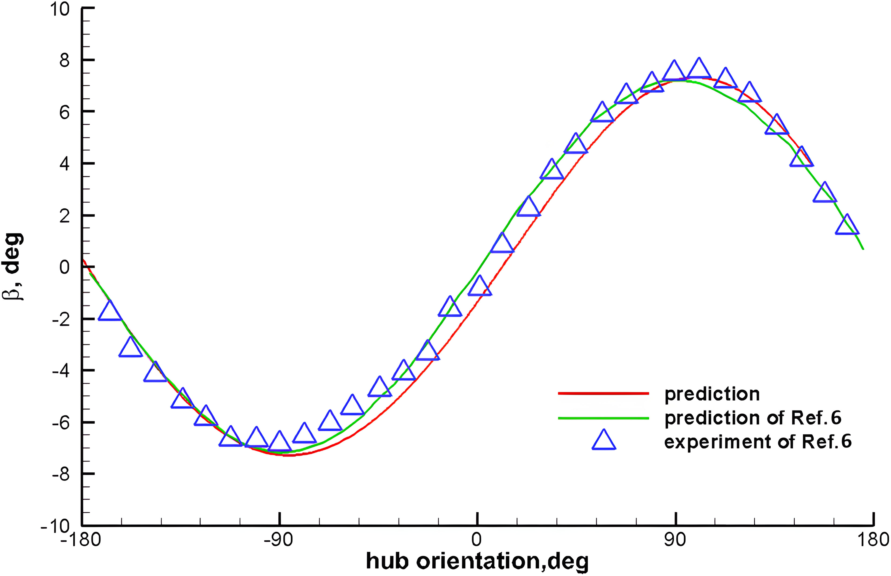
Flap angle response with sinusoidal torque.
Simulation analysis
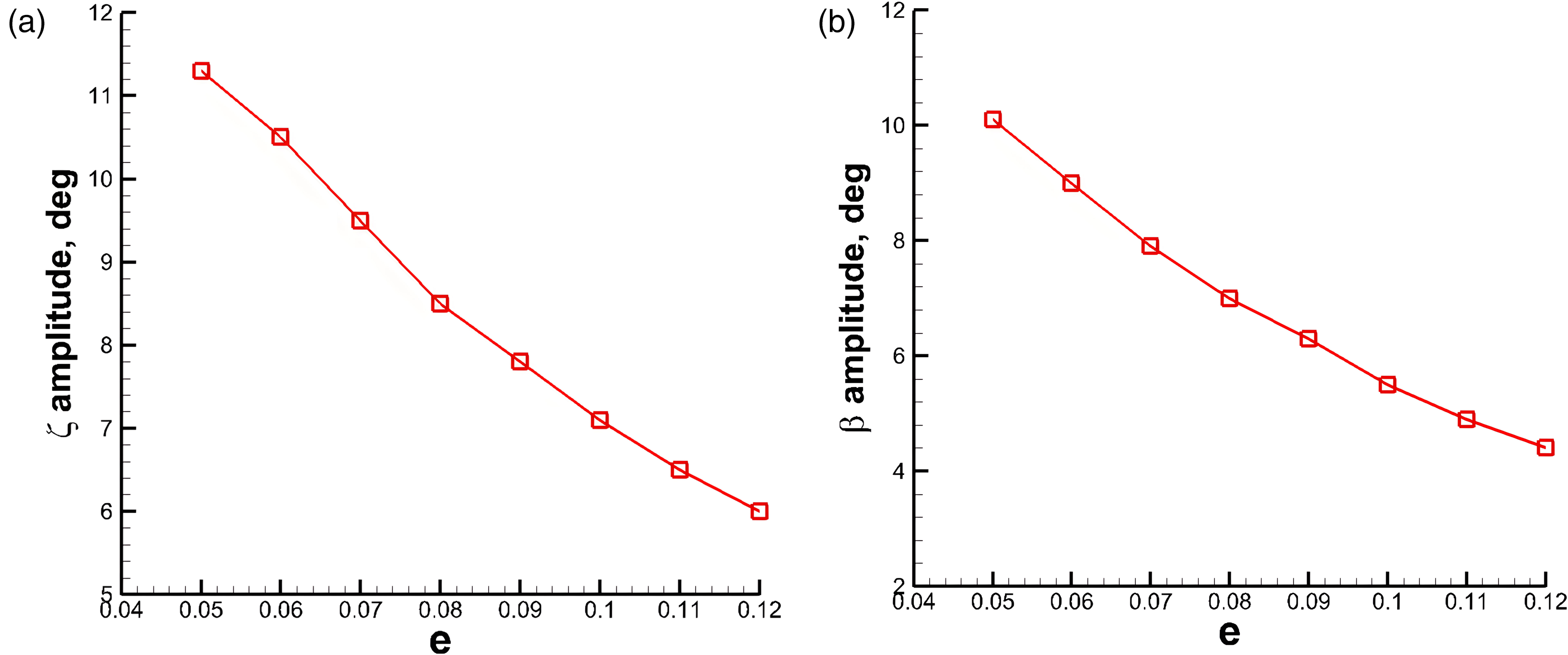
We ran a series of simulations to investigate the effect of hinge eccentricity on swashplateless rotor control. Under the control of exciting voltage amplitude of 1.75V at the average rotational speed of 200 rad/s, the simulation analyses of hinge eccentricity were carried out with different values. As shown in the Figure 12, with the increase of the hinge eccentricity, the lag angle amplitude and the flap angle amplitude of the blade decrease continuously. So with a smaller hinge eccentricity, the control sensitivity will be larger.
In order to study the influence of the inclined angle of lag-pitch hinge on the control of the swashplateless rotor, a series of simulations were conducted. The simulation analyses were carried out with different inclined angles of lag-pitch hinge under the control of an exciting voltage amplitude of 1.75V at an average rotational speed of 200 rad/s. As depicted in the Figure 13, as the inclined angle of the lag-pitch hinge increases, the lag angle amplitude of the blade decreases, but the flap angle amplitude of the blade increases significantly, implying that the amplitude of the blade angle of attack increases significantly. In other words, the greater the inclined angle of the lag-pitch hinge is, the greater the control sensitivity will be. However, with the consideration of rotor structure, the inclined angle of the lag-pitch hinge can’t be too large.

The advantage of the swashplateless rotor is that the actuators and complex mechanisms of the conventional rotor can be eliminated, achieving lightweight and miniaturization of the UAV. Therefore, the weight of the wingtip hammer should not be too large, otherwise it will violate the starting point of lightweight. Based on comprehensive considerations, the mass of the wingtip hammer is finally selected as 2g, and the simulation analyses were conducted by changing the station position of the wingtip hammer. We investigated the effect of wingtip hammer radial position on the control sensitivity of the swashplateless rotor with an average rotational speed of 200rad/s and an exciting voltage amplitude of 1.75V. As shown in Figure 14, with the increase of

Experimental result
Four groups of comparative experiments are carried out to verify the influence of hinge eccentricity on the control effect of swashplateless rotors, as shown in Figure 15 below. The driving signal in the experiments is the Dshot signal with an average value of 400 and a sinusoidal fluctuation amplitude of 160, which ensures the motor drive’s consistency. The moment of inertia of a swashplateless rotor hub will inevitably change as the eccentricity of the hinge changes. As a result of using the rotor inertia adjustment plate in the four groups of experiments, the rotor inertia of the four prototypes was essentially the same. Other parameters were also the same. In subsequent experiments, we also carefully controlled the irrelevant variables.

The motion picture captured by a high-speed camera of the swashplateless rotor prototype with different hinge eccentricities under the same input.
The final experimental results are shown in Figures 15 and 16. From the top view, we can see that the amplitude of lag angle decreases from
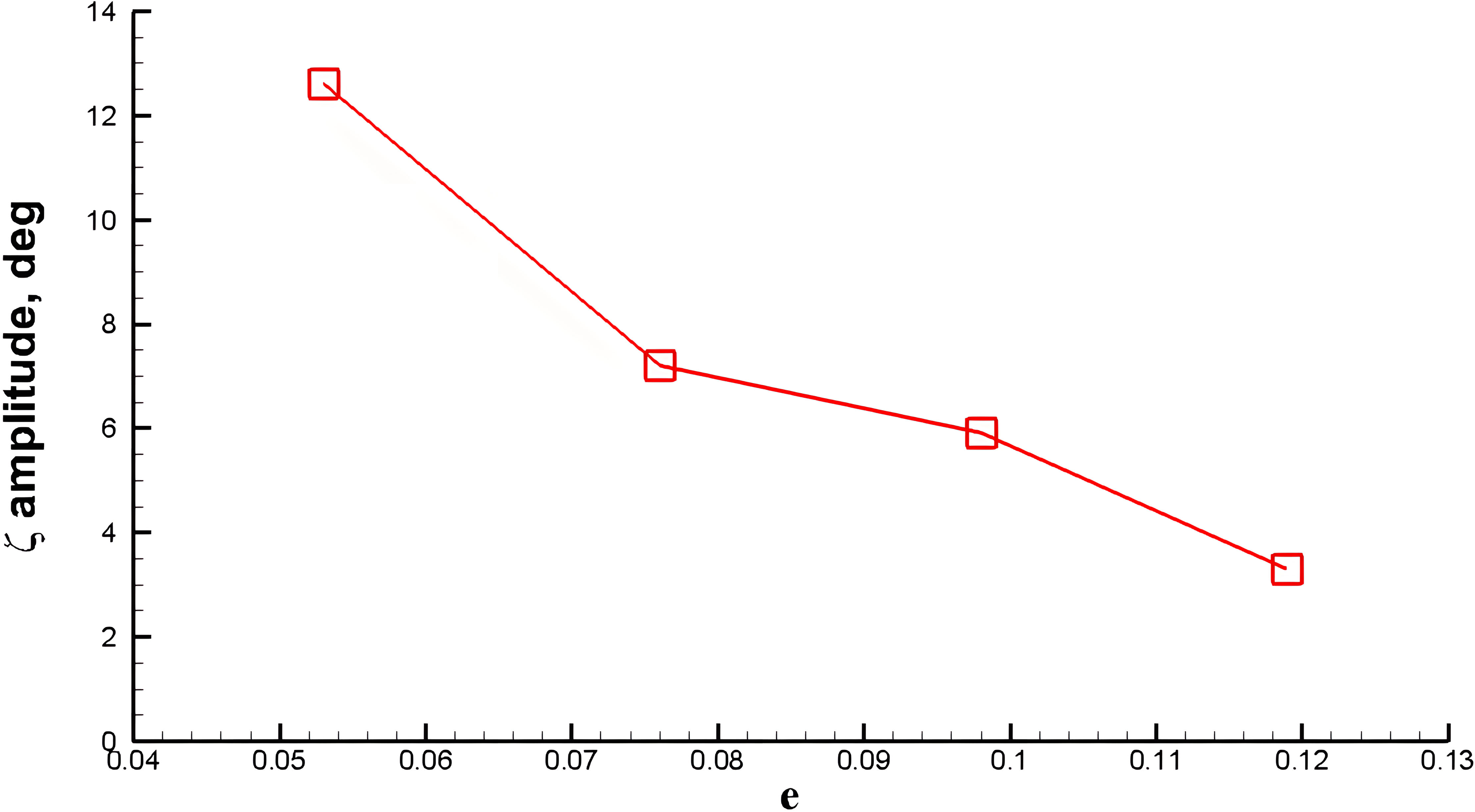
The relation between the amplitude of lag angle
The experimental results are in agreement with the amplitude variation predicted by theoretical analyses, which is of great significance for guiding the design of swashplateless rotor structure. From this result, we can see that reducing the hinge eccentricity e is a very effective design method for improving control sensitivity.
As shown in Figures 17 and 18, we carried out experiments on the effect of wingtip hammer on the control sensitivity of the swashplateless rotor. In these experiments, the mass of the white blade is around 3.3g. The wingtip hammer offset is 0.85. The mass of wingtip hammer is 1g, which is determined by considering the quality cost, the feasibility of machining and the influence on the aerodynamic shape of blade. Finally, through the comparative analysis of the experimental results shown in Figures 17 and 18 , it can be concluded that the amplitude of the lag angle and the flap angle of the blade decreased a little after the addition of the wingtip hammer. This is because the inertia force and centrifugal force which mainly lead the lag motion of blade are proportional to the eccentricity of the wingtip hammer. So no matter how the position of the wingtip hammer changes, the ratio of the two forces is nearly unchanged. And the amplitude of the lag angle will not change significantly. However, if the wingtip hammer’s weight and eccentricity are further increased, the motor speed fluctuation will be reduced due to the increase of the rotor inertia, and the control sensitivity will be worse.

Under the same drive, the lag angle of blade with and without wingtip hammer.

Under the same drive, the flap angle of blade with and without wingtip hammer.
The images in Figures 19 and 20 show that the flap angle of the blade increases as the inclined angle of the skewed lag-pitch hinge increases. This corresponds to our theoretical prediction, which demonstrates that increasing the inclination angle can effectively improve the control sensitivity of the swashplateless rotor. However, with the consideration of structure design and control, the inclined angle cannot be too small or too large. if the inclination angle is too large, it will be too sensitive to control. At the same time, it will be hard to design its structure. on the contrary, if the inclination angle is too small, there will be slight pith angle change, which is also a bad condition that we do not except to occur.

The motion picture captured by a high-speed camera of the swashplateless rotor prototype with different inclination angles of skewed lag-pitch hinge under the same input.
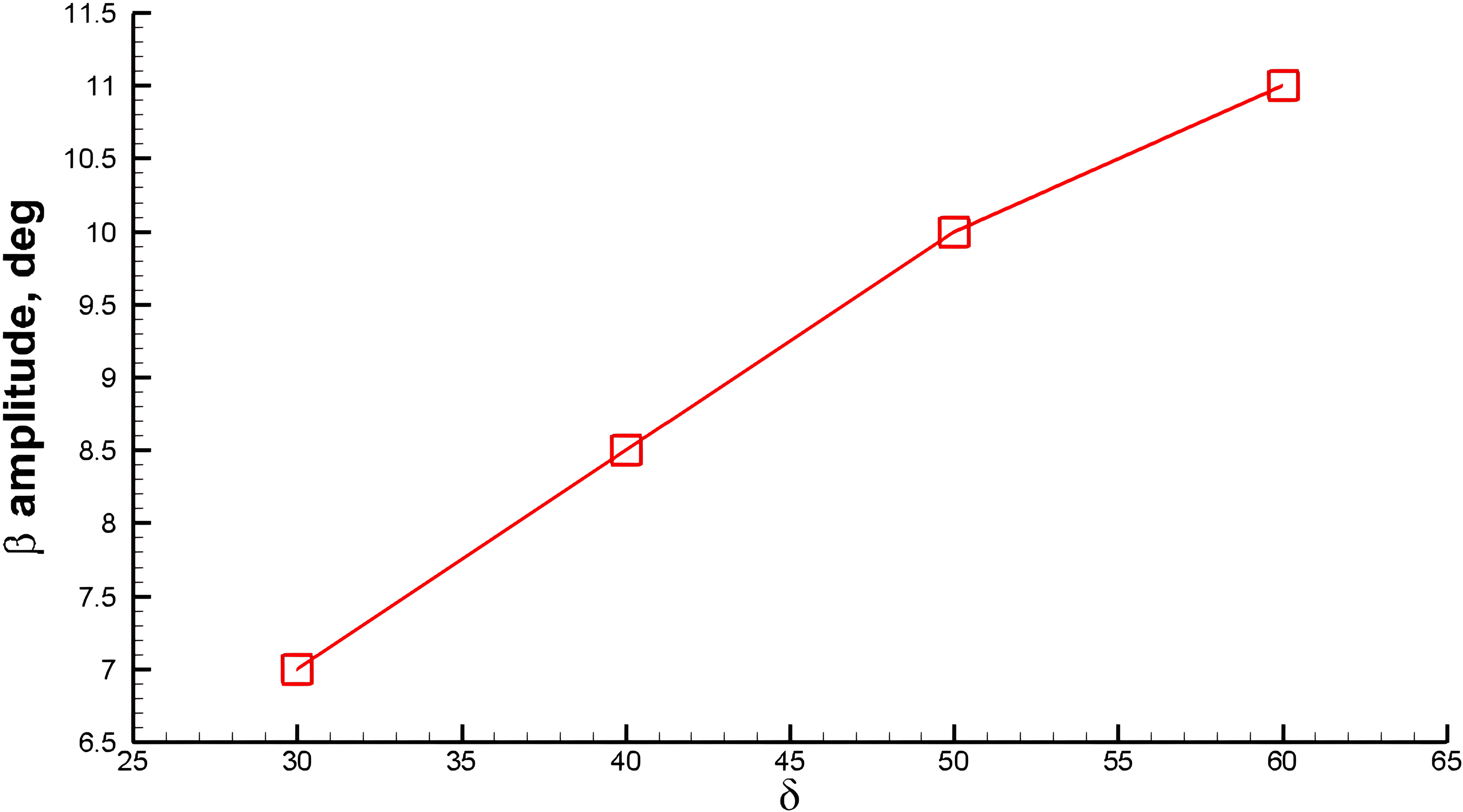
The relation between the amplitude of flap angle
In general, the experimental results are consistent with the theoretical prediction. And both simulation and experimental results show that the wingtip hammer does not provide the expected positive gain for the control sensitivity of the swashplateless rotor, which is useful information.
Conclusion
In this paper, the action mechanism and parameter effect on swashplateless rotor control are investigated further in the theoretical analysis and preliminary prototype experiments. In general, the dynamic model with wingtip hammer of the swashplateless rotor was established in this paper, and simulations and analyses were performed. Secondly, a prototype of the swashplateless rotor was built, and relevant experiments were conducted to validate the theoretical result. Finally, the following key conclusions were obtained:
Under the same control input, the larger the eccentricity of the inclined hinge is, the smaller the amplitude of the lag angle, pitch angle and flap angle can be controlled. With a certain range of inclined angle of lag-pitch hinge and the same control input, the larger the hinge inclined angle is, the larger the amplitude of pitch angle and flap angle can be controlled. the wingtip hammer doesn’t provide positive gain on the control sensitivity of the swashplateless rotor.
According to the preceding conclusions, a well-designed swashplateless rotor with high control sensitivity should have the following basic characteristics: 1. The eccentricity of the hinge is small; 2. the rotor’s mass is light; and 3. the inclined angle of the hinge is large enough but does not exceed the physical limit. The control sensitivity of the swashplateless rotor can be well guaranteed if the above basic characteristics are met. However, it should be noted that the control sensitivity improvement cannot be pursued blindly because the high-speed control capability of the motor is limited. Matching the high precision drive control ability will be difficult if the control sensitivity of the swashplateless rotor is too high. Therefore, the swashplateless rotor with high control sensitivity would be unable to control effectively and accurately.
Another key point we would like to emphasize is that the three basic characteristics are just heuristic design principles. Designers should adjust these parameters case by case. For example, if there are some geometric constraints such that hinge eccentricity can’t be less than 0.1, then designers will have to adjust the last two features to get satisfactory control sensitivity. And the specific design values require careful consideration of the geometric constraints and structural strength constraints to optimize them.
To summarize, every component of a swashplateless rotor system is interconnected tightly, and the entire rotor system must be properly integrated for optimal performance. And in the future, we will carry out further research to integrate this system into novel micro aerial vehicles to explore its practical potential.
Footnotes
Declaration of conflicting interests
The authors declare that there are no potential conflicts of interest with respect to the research, authorship, and/or publication of this article.
Funding
The authors received no financial support for the research, authorship and/or publication of this article: The work is funded by National Natural Science Foundation of China (No. 11902320) and Youth Innovation Promotion Association CAS (No. 2020149).