
Abstract
This paper investigates the influence of the fuselage arm cross-section shape on the aerodynamic and aeroacoustic performance of quadcopter Unmanned Aerial Vehicles in hover state by numerical simulation. The unsteady simulations of the flow field around one generic two-blade rotor and one fuselage arm are conducted by the Reynolds Averaged Navier-Stokes solver with the
Introduction
The increasing availability of quadcopter Unmanned Aerial Vehicles (UAV) or drones has powerfully extended humans’ ability to remotely observe objects of interest and to deliver goods, making it of fast-growing popularity in the application of landscape photography, 1 wildlife surveillance, 2 road traffic monitoring, 3 package delivery 4 etc.
Besides the resolving ability of the on-board cameras and sensors, the aerodynamic efficiency and the aeroacoustic noise level are two of the critical factors influencing the commercial and application values of the drones. In order to improve the aerodynamic efficiency, researches on isolated rotor shape, 5 rotor-rotor interaction6,7 and rotor-body interaction 8 have been conducted, which reveals the characteristics regarding the rotor flow field. Corresponding shape designs and optimizations could potentially enlarge the flight range or the payload, or could prolong the cruise time of drones. On the other side, the noise footprint of the drones would cause the distance dilemma 9 when monitoring wildlife or broadcasting live games. It would also encounter challenges from the communities as the goods delivery drones represent a unique community noise source. 10 To characterize the aeroacoustic noise of drones, a series of experimental and numerical studies has been conducted with different rotor blade designs,11,12 varying speed of rotations,13,14 varying rotor numbers 15 etc. To reduce the noise level of drones, noise reduction methods, such as propeller trailing edge serration,16,17 wavy rotor blade, 18 rotor phase synchronization, 19 have been investigated for quadcopter UAVs showing a potential reduction of aeroacoustic noise level.
With a considerable number of studies focusing on the rotor design of the drones, the effect of the fuselage arms on the aerodynamic and aeroacoustic properties has not drawn equivalent attentions. 20 However, the fuselage arm of the drones is a source of both aerodynamic loss and aeroacoustic noise. When the blade of the rotor passes over the fuselage arm, it induces on the upper surface of the arm a region of high static pressure. Such a pressure distribution on the fuselage arm cover surface would on one hand result in a rise in the rotor thrust but on the other hand cause a downward force on the arm. If the rotor and the fuselage arm were considered as a connected part, the total upward thrust would be reduced as compared to the isolated rotor without the fuselage arm. Similar to the rotor-vane interaction noise in the field of fan noise, the above rotor-arm interaction phenomenon could also cause the tonal aerodynamic noise to rise as a time-periodic pressure force is exerted on the fuselage arm surface as a result of the rotor blade's wake. To reduce the intensity of the rotor-arm interaction, a good number of practices could be taken following the research outcomes in the field of aero-engine studies. For example, the use of serrated rotor blade trailing edge to reduce the intensity of the rotor wake by enhancing turbulence mixing;21,22 or the use of leaned or swept arm23,24 to enlarge the rotor-arm distance.
By observing the fuselage arms of existing commercial UAVs, it is found that the shape of the fuselage arm cross-section varies from rectangular to circular. For example, the DJI Mavic series has a quasi-rectangular arm cross-section while the DJI Matrice series and Inspire series have circle-like arm cross-sections. Therefore, it is of interest to investigate the way and the amount the aerodynamic efficiency and the aeroacoustic noise level of the quadcopter UAVs are influenced by the shape of the fuselage arm cross-section.
In basic fluid dynamics, the drag force

By Computational Fluid Dynamics (CFD) simulations and analysis, the current paper compares the aerodynamic and aeroacoustic properties of different fuselage arm cross-section shapes and aims at providing practical guide to UAV fuselage arm design. To focus only on the effect of the rotor-arm interaction and to reduce the computational workload, the simplified configuration of one rotor and one fuselage arm only is adopted in the modelling. The tested shapes of the fuselage arm cross-section include square, circle, circle with rectangular slit, ellipse, semi-square and semi-ellipse. To make the comparison fair, the constraint of fixed cross-section area is applied to all the investigated fuselage arms. In the analysis, the measure of the aerodynamic performance is twofold with the main indicator as the total thrust force in the vertical direction and the secondary indicator as the transversal force. The acoustic property is obtained by analyzing the fluctuating pressure downside the rotor-arm model.
Numerical methodology
Rotor-arm model
As is explained in the introduction part, the simplified model adopted only contains one rotor and one fuselage arm neglecting the main body of the drones and the other rotors. A generic two-blade rotor model is employed to represent the rotor of a small size commercial quadcopter UAV. Figure 1 shows the configuration of the rotor-arm model. The outer radius of the rotor model is Rout = 0.049 m and the radius of the hub is 0.006 m (0.12Rout). The axis of the rotor is along the z-coordinate with the gravitational force pointing to the negative z-direction. The orientation of the fuselage arm is along the positive x-coordinate which is perpendicular to the rotor axis. The rotor and the fuselage arm are connected via a cylindrical hub of 0.026 m in length (0.53Rout). The distance between the rotor's rotational plane and the axis of the fuselage arm is fixed at 0.015 m. The distance between the rotor and the top of the hub is 0.006 m and that between the axis of the fuselage arm and the bottom surface of the hub is 0.005 m. While the geometry and the configuration of the investigated rotor-arm model does not correspond exactly to any existing quadcopter UAVs, the size of the rotor blade and the distance between the rotor and the fuselage arm conform to general values, which is sufficiently representative for the problem targeted by this paper.

Geometry of the rotor-arm model configuration (circular cross-section as an example).
With the rotor size and the rotor-to-arm distance fixed, the shape of the fuselage arm cross-section is the single control variable in the study. In the following simulations, fuselage arms with five types of cross-sections are investigated: 1) square arm, 2) circular arm, 3) circular arm with rectangular slit, 4) elliptical arm and 5) semi-square and semi-elliptical arm. To make the comparison fair, the areas of the five cross-sections are kept identical at 0.0001 m2. Detailed descriptions of the size of the cross-sections are illustrated in Figure 2.

Investigated geometry of the cross-sections of the fuselage arms.
Computational domain and settings
The computational domain is a cylindrical volume containing the rotor-arm model and its potential wake region. The basic size parameters are shown in Figure 3(a) where the outer radius of the domain is 0.15 m (3.06Rout) and the total axial length is 0.4 m (8.16Rout). The boundary surfaces of the computational domain are set to be pressure inlet/outlet conditions with atmospheric static pressure. In all the simulations of the current paper, the studied UAV is considered in hover state with zero flying speed applied. The speed of rotation of the rotor is chosen to be 6000 rpm, 9000 rpm and 12000 rpm with the blade tip Mach number 0.0898, 0.1346 and 0.1795 respectively.

Computational domain and mesh grid, (a) computational domain, (b) mesh grid in rotor region, wake region, on blade surface and arm fuselage surface.
The mesh grid consists of two parts that are connected by the boundary type of interface. In the domain of rotation as indicated by orange colour in Figure 3(a), the structured hexahedral mesh around the rotor blades is generated by the software of Turbogrid which is suitable for turbomachinery blade meshing. In the other domain, the mesh grid is created by Gambit. Detailed mesh structures near the rotor blade, in the domain of rotation and in the wake region are illustrated in Figure 3(b). Depending on the shape of the fuselage arm cross-section, the total mesh grid number in the simulations ranges from 6.09 million to 7.05 million.
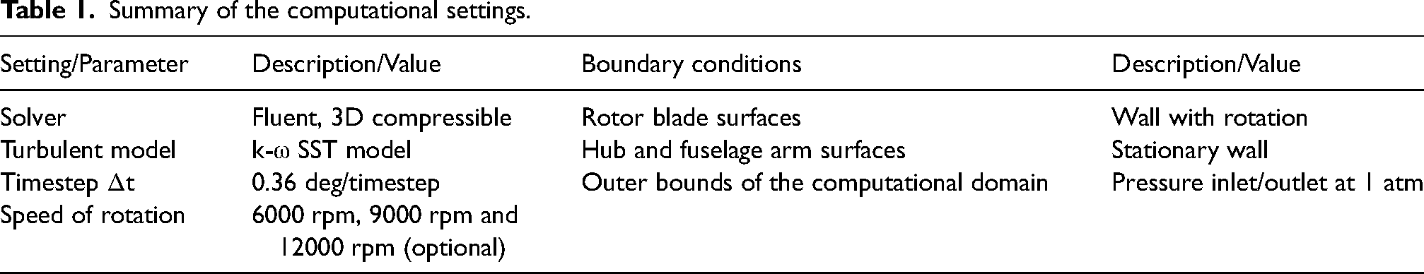
The flow field of the rotor is solved by the three-dimensional compressible flow solver in ANSYS Fluent v15.0. Due to the good behaviour in adverse pressure gradient flow and separation flow, the
Summary of the computational settings.
To evaluate the aerodynamic performance, the thrust and the transversal force on all the rotor and arm model surfaces are recorded as listed in Table 2, where the thrust force is considered the major measure of the aerodynamic efficiency while the transversal force represents the potential source of vibration in the transversal direction of the arm. To estimate the aeroacoustic performance, a pressure probe is set downside the rotor-arm model at [−0.1 m, 0 m, −0.05 m] as is shown in Figure 3(a). The pressure probe is positioned as close as possible to the rotating blade surfaces but outside the rotor wake region in order to capture the pressure fluctuations from the sound sources while avoiding the contamination from the pressure waves by the rotor wake flow. 31
Force diagram in the analysis of aerodynamic performance.

To check the independence of the computational grid, the rotor with square arm is employed. In the tested cases, the total mesh grid cell number in the computational domain varies from 4.56 million to 6.09 million where the mesh refinement level increases in the wake region while a fixed cell number of 2.45 million in the rotor region is kept. The predicted time-averaged thrust forces at 6000 rpm are listed in Table 3. From the table, it could be found that the predicted time-averaged force drops significantly when the total cell number increases from 4.56 million to 5.61 million, while it changes slightly when the total cell number further increases from 5.61 million to 6.09 million. Therefore, in all the other simulations the size of the mesh grid refers to that in the square arm case with 6.09 million mesh grid number.
Predicted time-averaged thrust forces as a function of grid cell number.

Isolated rotor in hover
Before investigating the aerodynamic and aeroacoustic performance of the quadcopter UAVs with different fuselage arm cross-sections, an isolated rotor in hover state case is studied in the first place to provide the data of reference. In this referential case, the model contains only one rotor and one cylindrical hub. All the computational settings are the same as those described in section 2.2.
In Figures 4 and 5 plot the unsteady thrust force and transversal force of the isolated rotor. It could be seen from the figure that the thrust and transversal forces vary periodically with time. The average thrust forces from t = 3 × 10⁻² s to t = 6 × 10⁻² s are respectively 0.2218 N for 6000 rpm case and 0.4897 N for 9000 rpm case. The thrust force at 9000 rpm is 2.21 times of that at 6000 rpm, which means that the thrust force is nearly proportional to the square of angular velocity of the rotor. Compared to the thrust forces, the amplitudes of the transversal force are much smaller. For the current configuration, the transversal force that induces transversal vibrations are of order 10−4 N (Figure 5).

Unsteady thrust forces for isolated rotor in hover state, left axis: @ 6000 rpm, right axis: @ 9000 rpm.

Unsteady transversal forces for isolated rotor in hover state, left axis: @6000 rpm, right axis: @9000 rpm.
Figure 6 plots the sound pressure level spectra in decibel at the probe point for the isolated rotor at 6000 rpm and 9000 rpm. It could be found that the spectra are characterized by a series of narrowband tonal peaks caused by the rotation of the rotor blades. For the 6000 rpm case, the fundamental blade passing frequency is at BPF = 200 Hz, where the shaft frequency is 100 Hz and the blade number is 2. The maximum sound pressure level of 71.87 dB appears at the fundamental frequency. At other higher order harmonics, the sound pressure levels are much lower. For the 9000 rpm case, due to an increased speed of rotation, the fundamental blade passing frequency is at BPF = 300 Hz and the sound pressure levels at the fundamental and each harmonic frequencies are 5 to 8 decibels higher than their correspondences in the 6000 rpm case.

Frequency spectra (sound pressure level) at the probe point.
Figure 7 shows the instantaneous vortex structure of the flow field at t = 4 × 10⁻² s. From the figure, it could be concluded that as the rotor blades turn, strong vortices are created near the tip of the blade. These vortices are stretched downstream by the main flow and finally form a helical-like flow structure.

Phase-averaged vortex structure (mean Q-criterion = 1000) of single rotor from t = 4 × 10⁻² s to t = 6 × 10⁻² s, (a) top view, (b) side view.
Results and analysis
In this section, the aerodynamic and aeroacoustic performances of the five fuselage arm cross-sections in Figure 3 are investigated. The five cross-sections are named orderly by case #1 (square cross-section), case #2 (circular cross-section), case #3 (circular cross-section with rectangular slit), case #4 (elliptical cross-section) and case #5 (semi-square and semi-elliptical cross-section). The unsteady simulations are conducted till t = 8 × 10⁻² s for all the tested cases. The data employed in the analysis only concerns those from t = 4 × 10⁻² s to t = 8 × 10⁻² s where the observed flow variables show good periodicity. Depending on the speed of rotation, the time-averaged forces are averaged based on data of 4 to 8 rotor cycles.
For the square and the circular cross-section cases, complete investigations of three speeds of rotation (6000 rpm, 9000 rpm and 12000 rpm) are conducted. In Section 3.2, the 12000 rpm case is omitted because the comparison of the thrust forces between 6000 rpm and 9000 rpm could already confirm the aerodynamic performances of the proposed cross-section shapes. The comparison of the transversal forces is also omitted when the observed thrust forces are of obvious difference.
Fuselage arm with square and circular cross-sections
First, the fuselage arms with square cross-section (case #1) and circular cross-section (case #2) are compared. These cross-section shapes are two of the most commonly applied shapes in commercial quadcopter UAVs. The comparison of the results could tell the aerodynamic and aeroacoustic performances of the two basic shapes. The results could also serve as reference for other fuselage arm cross-section designs.
Figure 8 plots the simulated thrust forces of case #1 and case #2 at three speeds of rotation. The thrust force for the rotor-arm configuration is the total downward force on all the cover surfaces of the rotor blades, the hub and the fuselage arm. From the figures, it could be firstly observed that the thrust forces for the rotor-only cases are much higher than those for the rotor-arm configurations at the same speed of rotation, which confirms that the addition of the fuselage arm would cause a decrease of the total thrust force.
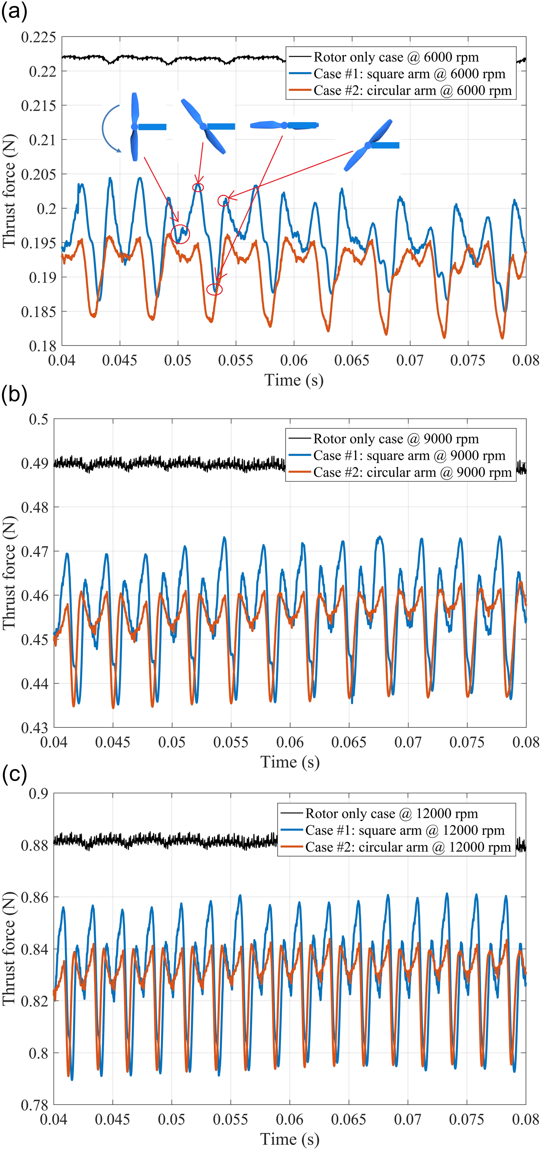
Comparison of the thrust forces for square cross-section and circular cross-section, (a) @6000 rpm, (b) @9000 rpm and (c) @12000 rpm.
In Figure 8(a), the variation of the thrust force is plotted with the turning angle of the blade. At t = 5 × 10⁻² s where a new rotor cycle starts, the thrust force for case #1 is about 0.195 N. As the blade turns toward to fuselage arm, the thrust force increases gradually to a maximum value of 0.2305 N. At this angular position of rotor blade, the rotor blade is squeezing the air between itself and the fuselage arm while the fuselage arm serves as a stator that would increase the thrust force. When the rotor blade coincides with the fuselage arm, the thrust force reaches its minimum value of 0.1879 N because the fuselage arm blocks the flow that is going downstream. Finally, the rotor blade turns away from the fuselage arm. At this point, the blade sweeps the higher pressure air previously in the region between the blade and the fuselage arm downstream. This would cause an increase in the thrust force.
In terms of averaged forces. The square cross-section arm has higher thrust forces as compared to the circular cross-section arm. The average thrust forces for the square cross-section case are 0.1951 N at 6000 rpm, 0.4564 N at 9000 rpm and 0.8299 N at 12000 rpm, while those for the circular cross-section case are 0.1908 N, 0.4529 N and 0.8279 N respectively. One of the reasons that the square cross-section arm case has higher thrust force might be that it has a smaller frontal area. At 6000 rpm, the square cross-section fuselage arm provides 2.25% more thrust force than that of the circular cross-section arm. This difference in thrust force should be paid attention to in the design process as the commonly employed rotational speed range of small quadcopter UAVs is between 5400 rpm to 7200 rpm.8,16,32 However, the advantage of the square cross-section arm in providing higher thrust force decreases as the speed of rotation increases. For the 9000 rpm case and 12000 rpm case, the square cross-section arm could only provide 0.77% and 0.24% more thrust force.
Figure 9 plots the simulated transversal force of case #1 and case #2. For the square cross-section case, the maximum amplitudes of the transversal force variations are 0.0171 N at 6000 rpm, 0.0297 N at 9000 rpm and 0.0554 N at 12000 rpm, which are respectively 39%, 16% and 2.7% larger than those for the circular cross-section arm. This indicates that although the square fuselage arm permits more thrust forces, the unsteadiness of the aerodynamic force in the translational direction is more serious.

Comparison of the transversal forces for square cross-section and circular cross-section, solid lines: square cross-section, dashed lines: circular cross-section.
Figure 10 compares the sound pressure level spectra in decibel at the probe point. Contrary to the aerodynamic performance, the circular cross-section case shows better aeroacoustic performance for the tested speeds of rotation. At 6000 rpm, the sound pressure levels are 69.76 dB for the circular cross-section case and 71.67 dB for the square cross-section case at the blade passing frequency of 200 Hz. At the first harmonic of the blade passing frequency (400 Hz), the sound pressure levels are 54.20 dB for the circular cross-section case and 58.71 dB for the square cross-section case. For higher speeds of rotation, the advantage in aeroacoustic performance of the circular cross-section case becomes marginal. At 9000 rpm and 12000 rpm, the sound pressure levels at the blade passing frequency for the circular cross-section case are 1.52 dB and 1.21 dB lower as compared to the square cross-section case.

Comparison of the sound pressure level spectra for square cross-section and circular cross-section.
Figure 11 plots the instantaneous vortex structures for the square cross-section case and the circular cross-section case. Compared with the vortex structure plot in Figure 7, the addition of the fuselage arm breaks the helically spinning vortex structure downstream the rotor. As could be observed in Figure 11, the vortex structure of the square cross-section case is larger and extends further downstream as compared to that of the circular cross-section case.
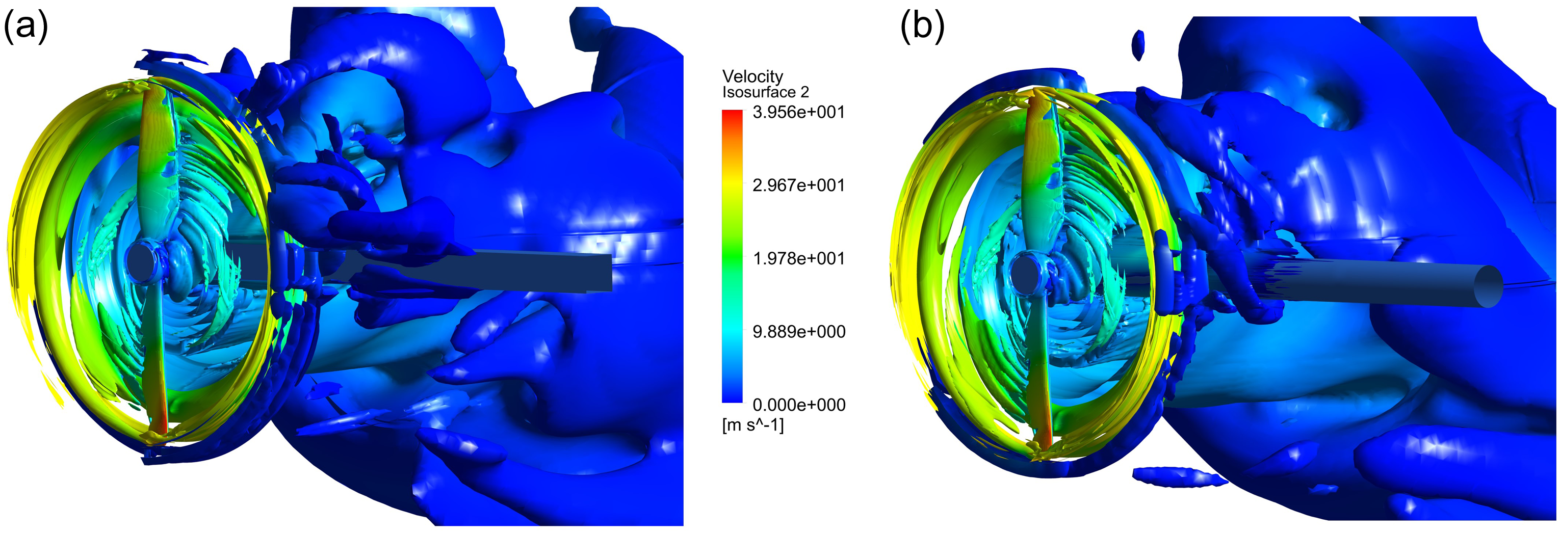
Phase-averaged vortex structure (mean Q-criterion = 1000) from t = 4 × 10⁻² s to t = 6 × 10⁻² s, (a) square cross-section, (b) circular cross-section.
Fuselage arms with other cross-section shapes
Circular cross-section with rectangular slit
Figure 12 compares the thrust forces of the circular cross-section with rectangular slit (case #3) with that of case #2. From the figure, it could be seen that case #3 has comparable thrust forces as the circular cross-section case. The average thrust force at 6000 rpm is 0.1902 N for case #3 while that of the circular cross-section case is 0.1908 N. For the 9000 rpm case, the average thrust force for case #3 is 0.4511 N and that of the circular cross-section case #2 is 0.4529 N. No visible improvement, in terms of aerodynamic thrust force, is accomplished by a parallel rectangular slit in the arm cross-section. This means that although slitting might be able to reduce the drag force of cylinder in flow under some circumstances as is reported in the literature,25,26 it does not apply for the quadcopter UAVs’ fuselage arm. In fact, as is explained in Section 3.1, the magnitude and the direction of the flow variables around the fuselage arm varies with the turning angle of the rotor blade. The problem herein is no longer comparable to the classic flow-past-cylinder problem with uniform incoming flow. The three-dimensional effects of the flow could not be ignored.

Comparison of the thrust forces for the silted circular cross-section and the circular cross-section, (a) @ 6000 rpm, (b) @ 9000 rpm.
Since the gap of the observed thrust forces between case #3 and case #2 enlarges as the speed of rotation increases, it could be expected that case #3 would not have superior aerodynamic performance at 12000 rpm over case #2. Therefore, the comparison @ 12000 rpm is not provided herein. The same reason for case #4 and case #5 in the following subsections.
Elliptical cross-section
According to the result comparison in Section 3.1, from the point of view of fuselage designing, it might be inferred that one of the reasons that the square cross-section case has higher thrust force is that it has smaller frontal area as is shown in Figure 2. Another consideration is that prolonging the shape of the cross-section in the main flow direction, like the shape of an airfoil, would provide better wake separation control and thus could help to reduce the drag force. With the above two reasons, the elliptical arm cross-section case (case #4) is tested because it keeps the same frontal area as the square cross-section case meanwhile it is more prolonged in the downstream direction as compared to case #1 and case #2.
However, as is shown in Figure 13, the thrust forces for the elliptical cross-section case are smaller than the circular cross-section case. The average thrust forces at 6000 rpm and 9000 rpm are 0.1855 N and 0.4455N, which are 2.47% and 1.63% lower than those of the circular cross-section case.

Comparison of the thrust forces for the elliptical cross-section and the circular cross-section, (a) @ 6000 rpm, (b) @ 9000 rpm.
The elliptical cross-section case, having the same frontal area as the square cross-section case and theoretically better wake separation control, has inferior thrust force in reverse. The elliptical cross-section is more prolonged along the main flow direction, but at the same time, it is more prolonged in the upstream direction toward the rotor blades as well with the positions of the geometrical centres of all the tested cross-section shapes fixed. This makes the upper cover surface of the elliptical arm to be placed closer to the rotor blades. When the cover surface of the arm is closer to the rotor, it would induce stronger rotor-arm interaction which would deteriorate the thrust performance.
Semi-square and semi-elliptical cross-section
The semi-square and semi-elliptical cross-section case shortens the cover surface extension in the upstream direction while keeping a prolonged profile in the downstream direction (Figure 2). However, simulation results still show that the thrust forces with semi-square and semi-elliptical arm are inferior to the circular cross-section case as is shown in Figure 14. At 6000 rpm, the average thrust force for the semi-square and semi-elliptical cross-section case is only 0.18 N, which is 5.66% lower than the circular cross-section case. At 9000 rpm, the gap reduces to 4.7% but the thrust force for case #5 is still smaller than case #2.
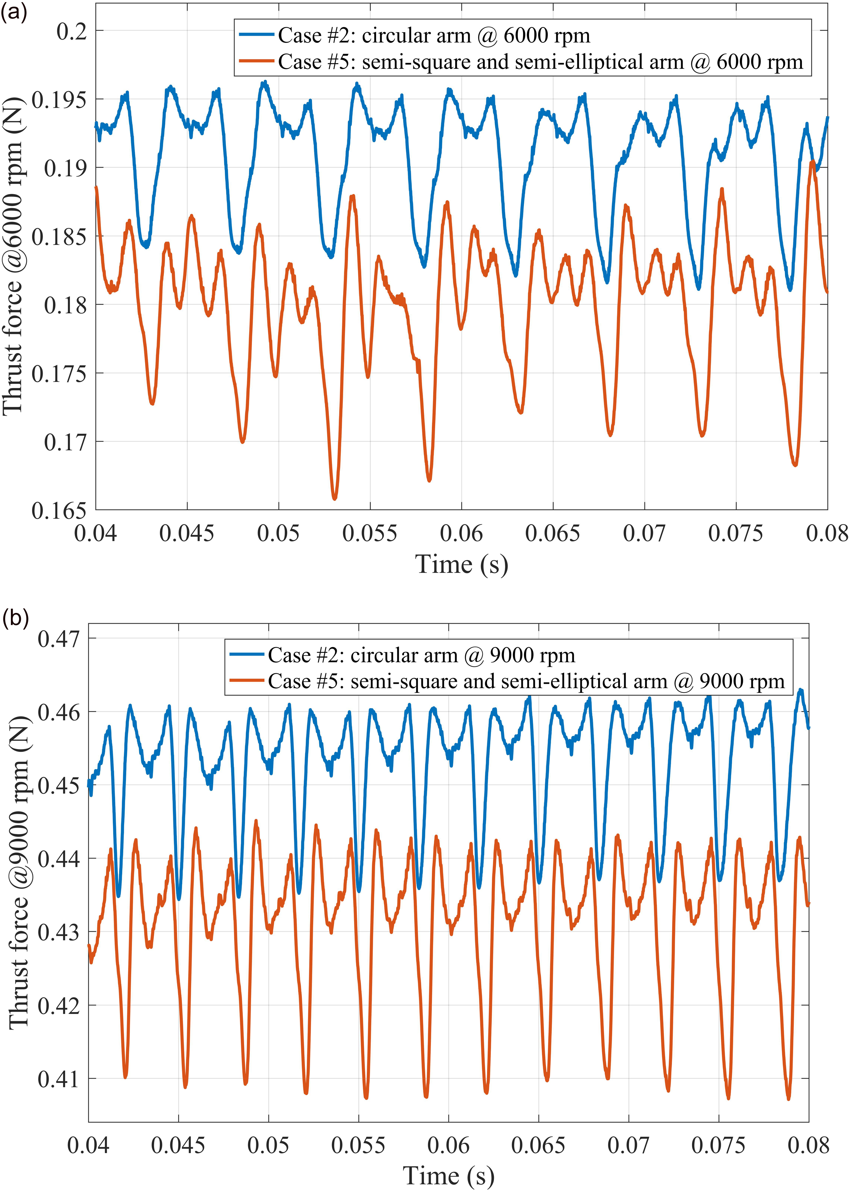
Comparison of the thrust forces for the semi-square and semi-elliptical cross-section and the circular cross-section, (a) @ 6000 rpm, (b) @ 9000 rpm.
With the same frontal area and the upper cover surface extension upstream as the square cross-section case, the semi-square and semi-elliptical cross-section case still could not achieve better aerodynamic performance. This indicates that the prolonged shape downstream aiming at providing better wake separation control is also not applicable in this case. The reason is also the three-dimensional effect and time variation of the flow field around the fuselage arm.
Summary of results
Table 4 summarizes the simulated aerodynamic and aeroacoustic performances for the tested 5 cross-section shapes. In terms of aerodynamic performance, the fuselage arm with square cross-section has the highest total thrust forces at all the tested speeds of rotation. The circular arm cross-section has the second largest thrust forces. Adding a rectangular slit on the circular fuselage arm could not enhance the aerodynamic performance of the UAVs as is opposed to the findings reported in the literature for flow-past-cylinder studies. The elliptical cross-section and the semi-square and semi-elliptical cross-section also do not show enhanced aerodynamics performances. One critical reason might be that the amplitude and direction of the flow field around the fuselage arm are time-varying depending on the rotational angle of the rotor blades. Therefore, simply prolonging the fuselage arm cross-section in the downstream direction would not help to control the separation of the wake and would not reduce the drag force of the arm.
Summary of the simulation results.

In terms of aeroacoustic performance, the fuselage arm with circular cross-section has the lowest sound pressure level at the first blade passing frequency. The square arm case, whose aerodynamic performance is better than the circular arm case, has inferior aeroacoustic performance. Apart from the two basic cases, the other three cases have obviously higher sound pressure levels at the blade passing frequencies. With lower thrust forces and higher sound pressure levels, the circular arm with rectangular slit, the elliptical arm and the semi-square and semi-elliptical arms are not good choices for UAV applications.
Conclusions
This paper intends to investigate the influence of the fuselage arm cross-section shape on the aerodynamic and aeroacoustic performance of the quadcopter UAVs by numerical simulation and provides practical guide for the design of UAV's fuselage arm. The total thrust forces and the sound pressure levels of five cross-section shapes with the same cross-section area are simulated and compared. Results show that the fuselage arm with square cross-section has the highest thrust force. The one with circular cross-section has the second highest thrust force. The gap of the thrust force between the circular cross-section case and the square cross-section case reduces from 2.25% to 0.24% as the speed of rotation increases from 6000 rpm to 12000 rpm. The other three tested cross-sections have inferior aerodynamic performances as compared with the square and circular cases. In terms of aeroacoustic performance, the case with circular cross-section has the lowest sound pressure levels at the blade passing frequencies. The other four tested cases have obviously higher tonal noise level.
From the simulation results of the current paper, it could be concluded that the fuselage arms with a square cross-section or a circular cross-section would be good choices for UAVs. The square cross-section arm provides better aerodynamic performance while the circular cross-section provides better aeroacoustic performance. It could also be concluded that the flow field around the fuselage arm is time-varying both in flow direction and amplitude. Therefore, drag reduction techniques for a uniform steady income flow problems, like slitting on the arm or airfoil-like shape of the arm, are not quite suitable for this specific problem herein.
Footnotes
Data availability
The data in the paper is available upon request to the corresponding author.
Declaration of conflicting interests
The authors declared no potential conflicts of interest with respect to the research, authorship, and/or publication of this article.
Funding
The authors disclosed receipt of the following financial support for the research, authorship, and/or publication of this article: This work was supported by the Doctoral Research Foundations of Shandong Jianzhu University, China, Shandong Provincial Natural Science Foundations of China, (grant number X21107Z, X21108Z, ZR2021QG061, ZR2021QG150).