
Abstract
Here, we demonstrate obstacle and secondary drone avoidance capability by quadcopter drones that can perceive and react to modulation of their self-generated acoustic environment when in proximity to surfaces. A ground truth for the interpretation of self-noise was established by measuring the intrinsic, three-dimensional, acoustic signature of a drone in an anechoic chamber. This was used to design sensor arrangements and machine learning algorithms to estimate the position of external features, obstacles or another drone, within the environment. Our machine learning approach took short segments of recorded sound and their Fourier transforms, fed these into a convolutional neural network, and output the location of an obstacle or secondary drone in the environment. The convolutional layers were constructed with a suitable topology that matched the physical arrangement of the sensors. Our surface detection and avoidance algorithms were refined during tethered flight within an anechoic chamber, followed by an exercise in free flight without obstacle avoidance, and finally free flight obstacle detection and avoidance. Our acoustic sense-and-avoid capability extends to vertical and horizontal planar surfaces and tethered secondary drones.
Keywords
Introduction
Many methods exist by which a drone might sense its environment, such as LIDAR and laser range-finders, 1 cameras and optical flow sensors, 2 pressure sensors, 3 or even bioinspired “hair sensors”.4,5 Each such sensor modality has strengths and weaknesses.
Another method of environmental detection is acoustic sensing with microphones. These have been used to estimate the distance 6 and bearing 7 between drones and the relative location of drones 8 in a swarm. Drone mounted acoustic sensors, with integrated MEMS and particle velocity sensors, have been shown to be capable of detecting the location of large civil aircraft. 9 Ground based acoustic sensors have also been used to localise small gasoline-powered UAV over hundreds of meters. 10
Acoustic surface detection methods have enjoyed success on robotic platforms drawing inspiration from biological systems. 11 Echolocation has been used to relocate a robot in an environment by comparison with existing maps of said environment. 12 Active echolocation has also been employed on the crazyflie drone to identify surfaces, 13 though this requires a loud on-board speaker to generate the required sound, which we wish to avoid.
Flying drones generate sound, principally from the motors and the aeroacoustic noise from the propellors (which we term the acoustic signature), and nearby surfaces in the environment reflect that sound. The spatio-temporal structure of the reflected acoustic signature contains information about the position of the drone relative to obstacles in the environment. Microphones that observe this information can also detect the acoustic signature of other drones in the environment. While physics based acoustic modelling approaches have been shown to be theoretically viable for surface detection in real time, 14 here we employ a machine learning approach.
This method of obstacle and drone detection offers several advantages over others. Unlike cameras, microphones work in the dark and draw minimal power; our arrays draw only a few mA. This makes them suitable even for micro-drones weighing only a few tens of grams.
They can be used passively to listen for the sound of other drones, or actively by listening to the reflected sound of the drone’s own acoustic signature. In either case, they make such a drone no more conspicuous than it would be operating in free flight, since a flying drone must operate its motors to resist gravity regardless of whether or not it is sensing the environment. This in contrast to laser range-finding or LIDAR; if a laser beam is directed at a suitable sensor it can be readily detected and the direction of the drone quickly determined.
The approach is also more general than sensing environmental changes by monitoring motor power consumption directly. Such sensing can be used to detect a surface below a drone and shut off the motors for landing (for example in Honeywell 15 ), but has limited utility for sensing vertical planar surfaces in the environment and no capability to detect other drones.
Here, we show how to use such information to detect surfaces, both in ideal conditions while tethered in an anechoic chamber, and in the variable, suboptimal conditions that occur in free flight. We then demonstrate how such information can be used to avoid collision with obstacles in free flight.
Finally, we demonstrate how such a sensor system can be used to detect another drone’s location in the environment, while tethered, with a high degree of accuracy.
Methods
Acoustic sensors
We have developed several acoustic sensor systems as required, including tethered analogue microphone arrays, on-drone analogue microphone arrays digitised by an onboard microcontroller, and onboard digital microphones managed by an onboard microcontroller (Figure 1). While specialised small, directional acoustic sensors do exist we opted for an array of microphones similar to those that have already seen successful employment on drones. 16 Directional microphones were rejected because it was felt having multiple recordings on an array would allow for better detection of interference effects.
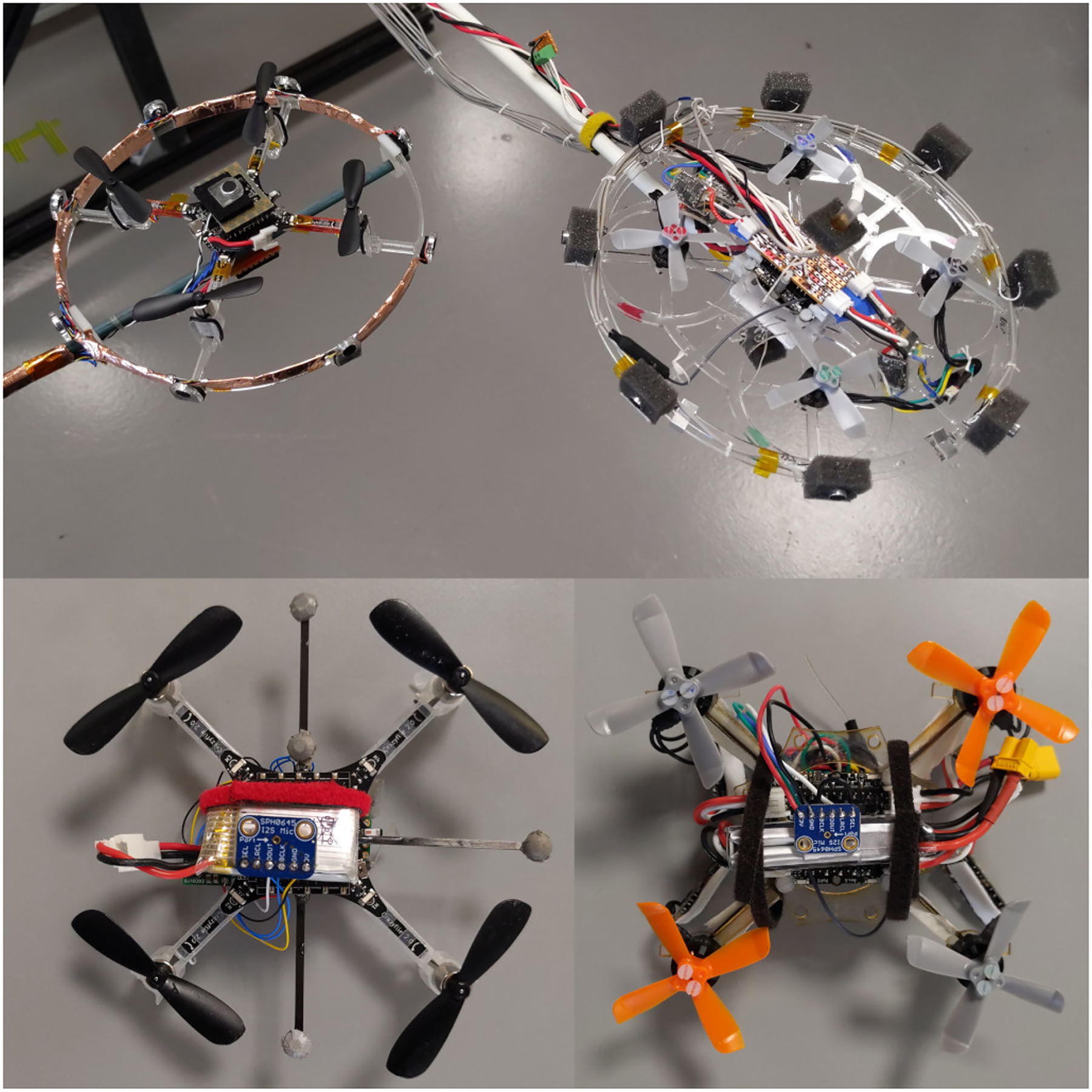
Various microphone arrays deployed on the Crazyflie and Mormoops prototype. At the top are the analogue microphone arrays deployed in a ring around the Crazyflie on the left and the Mormoops on the right. Below are the digital microphone arrays (in ground detection configuration with microphones on top of and below the drones body), again with the Crazyflie on the left and the Mormoops on the right). The bottom left drone was the final prototype used in the sense and avoid experiments.
The outputs from tethered analogue microphone arrays were digitised during the characterisation of the acoustic signature of the Crazyflie, and for tethered surface detection in the anechoic chamber, and for the detection of anther drone in the environment when both drones were tethered.
Following measurements of the acoustic signature of the drones and the tethered trials, for our recordings in free flight we used digital
Self-generated drone acoustic signature
In order to design and calibrate our surface detection algorithms for our drone, we needed to to obtain the self-generated acoustic signature: that is, the sound the drone made in various directions while hovering.
To do this, we mounted an array of analogue acoustic microphones on a Crazyflie and recorded the sound generated at a fixed distance at a range of angles (elevations at

Apparatus for measuring quadcopter acoustic signature. The arc is fitted with five microphones and can be rotated in azimuth to repeatable angles around the tethered quadcopter. Microphones are mounted at the North and South poles, the equator and
We took recordings in an anechoic chamber (Figure 2) to maximise the quality of the acoustic signature signals, shown in Figure 5.
Tethered surface detection using self-generated sound
Based on the results from the self-generated acoustic signature of our drones (Figure 5), we designed a microphone array for detecting surfaces in the environment with a high density of sensors at eight different azimuthal angles and two sensors above and below the drone (Figure 1, top right). We used this array to detect detect planar surfaces while tethered in an anechoic chamber using self-generated noise.
Based in part on the results from the acoustic signature of the drone we decided to implement a machine learning classifier built using PyTorch. 17 The classification network is built from a configurable input layer, two convolutional layers, two fully connected layers and an output layer.
The input layer can be adjusted to match the sensor suite being used via a human readable YAML configuration file. In this configuration the data is split into blocks.
These blocks are the microphone recordings from the eight sensors in a ring, the two microphone on the top and bottom of the drone, and two additional blocks formed from the Fast Fourier Transform (FFT) of these two sets of signals. The FFT was taken along the time axis of each block using the rfft function of tensor flow.
Two convolutional layers are then used. A useful summary of recent applications is provided in Jiuxiang et al. 18 The surrounding sensors form a ring around the drone, and any classification network should respect this topology, i.e. there should be no ‘start’ or ‘end’ sensor, and any mathematical operation should be invariant to a transformation which shifts all the sensors around this ring.
As such we use a circular convolution for the sensor input elements on the ring. Since the top and bottom elements of the microphone are completely included in the convolution along the sensor number axis, these can be a regular convolution.
If

All units in the network are Rectified Linear Units
19
(ReLU) to improve training and speed convergence, and so this response

Our network then proceeds with another convolutional layer with ReLU and pooling. Next, we have two fully connected layers. We treated the output of the last convolutional layer as a single vector

Another fully connected layer is then used followed by the output layer. The output layer is, for this case, the azimuthal angle of the obstacle, and a vector pointing to the obstacle in the plane. The azimuthal angle can only be
The network is trained using Stochastic Gradient Descent (SGD) 21 to minimise the mean square error.
The network performance was evaluated on a test data set of ten thousand sections two milliseconds in length that were not used in the training data. As the testing and training data are drawn randomly from sixty second length trials there is a risk that temporal correlation within the longer trials could allow for identification of the sample.
Surface detection in free flight
As a precusor to surface avoidance we created a version of our prototype drone with the ability to detect surfaces in free flight. The prototype (called Mormoops) consisted of a Bolt flight controller (Bitcraze, Malmö, Sweden), a custom chasis and four Betafpv 1105 5000KV brushless motors Betafpv, Hong Kong, PRC). The drone was operated near a planar surface, and our neural network tasked with detecting the surface.
A Centeye optical flow sensor, (Centeye, Washington, DC, USA) was used to measure the change in height of the drone over one minute trials. The flight controller maintained constant height based on optical flow odometry and no obvious drift was observed over these short flights. The drone was flown at three different heights, one deep in ground effect at approximately
Surface detection in free flight benefits from higher bandwidth microphone recording and processing. As such we decided to use a digital microphone platform combining SPH0645LM4H
This would allow us to use the Teensy microcontroller’s specialised
Our neural network was then required to distinguish these states using the sound recordings from
Free flight surface avoidance
Tests of wall detection capabilities were performed during the previous free flight experiments. However, this version of our drone could not safely resist wall effect, so insufficient training data could be gathered.
We modified our algorithms to detect and avoid both horizontal (ground) and vertical (wall) planar surfaces in free flight. We used the difference in power of the recording from two notch filtered microphones, a method that was based on examination of the structure of the machine learning approach – specifically the frequency dependency – and required minimal tethered training data.
The controller requires platform-specific calibration. The frequency range of the notch filter is specific to the drone that carries the sensor package, as are the gains on the microphones, and the threshold for detection. Ground detection is insensitive to these parameters, with simple benchtop tests sufficient for a good calibration. Wall detection requires in-flight refinement and iteration and is less reliable. In both instances the threshold for engaging the avoidance behaviour had to be set prior to the test.
At present, for avoidance purposes the system behaves as a classifier (the conditions being “wall present” and “no wall”). For the ground plane this is a simplification of the multiple heights that can be discerned by the machine learning controller, but for wall detection little evidence of continuous signal was apparent beyond the simple detection of wall effect.
Once an estimate of the surface position is available on the Teensy microcontroller, the information is communicated to the onboard Crazyflie flight controller by a parallel digital on the GPIO pins (Figure 1). This distance estimate is then transmitted, via the Crazyradio, to a computer that tracks the Crazyflie using a Qualisys motion capture system (Qualisys, Göteborg, Sweden). (Figure 3)
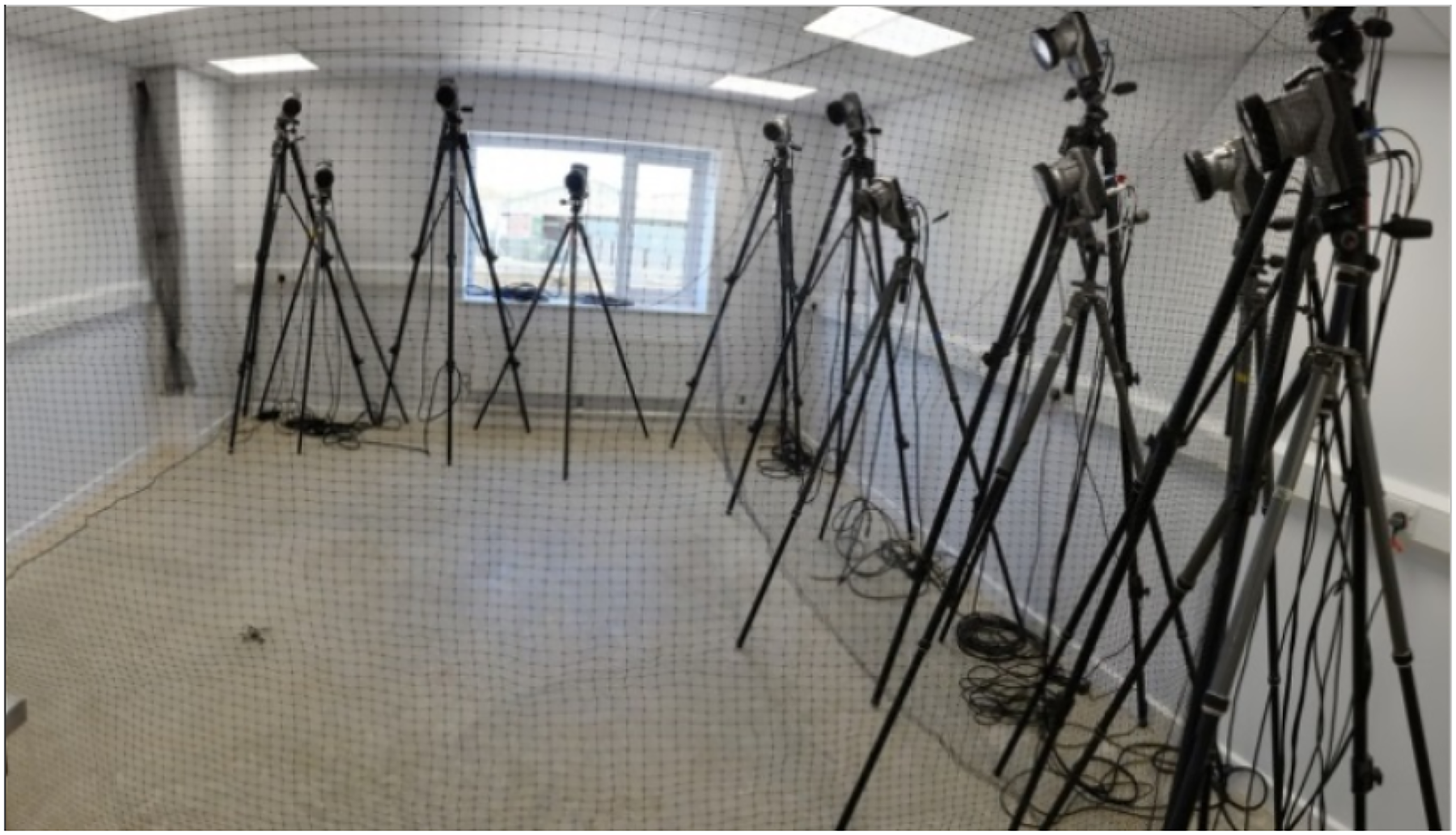
Image of the autonomous flight arena during its early development showing Qualisys motion tracking cameras and a Crazyflie UAV on the floor in the centre of a netted enclosure. This was used to track and control the Crazyflie during sense-and-avoid flight trials.
If an obstace is detected, evasive action is taken to reposition the drone by updating the target position set on the control computer.
Sensing other drones
We determined to what extent it was possible to identify a second drone using the same acoustic sensor array. Initially, we confined our considerations to detecting drones that are physically different, the Crazyflie and our new Mormoops drone.
We ran both drones simultaneously in tethered flight and recorded the acoustic signature of each at a range of distances and angles, as in Figure 4. The objective was to use our microphone array and machine learning approach to detect and locate the secondary drone, from the observer drone.
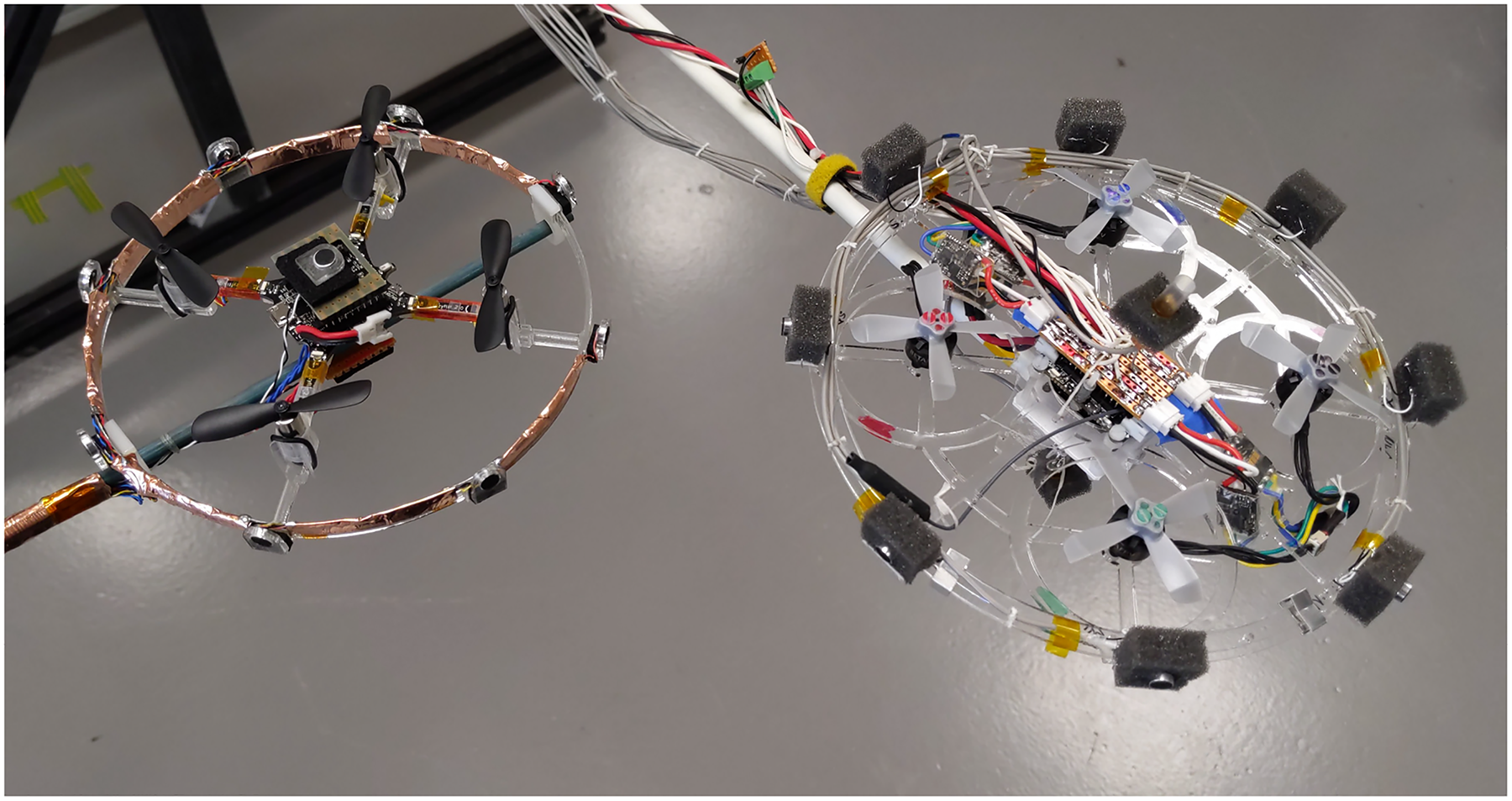
Experimental configuration for detecting and localising a prototype Mormoops drone from a Crazyflie, and vice versa. Recordings were taken from the microphone array on each drone, and used in conjunction with our machine learning approach to identify and localise each drone.
The analogue array was used to record from ten microphones distributed as for tethered surface detection. Recordings were performed in the same manner, though outside of the anechoic chamber due to space constraints.
Results
Self-generated drone acoustic signature
Acoustic signatures are shown in Figure 5. Position dependent differences are apparent in these signals, which suggested that discerning positional information about quadcopters from external acoustic recordings was highly feasible. The spatial distribution of the signal suggests the need for multiple sensors around the body of the drone. These results suggested, and later observations confirmed, that a single pair of microphones mounted above and below the body would be sufficient in these directions for planar surface detection.

The external acoustic signature of a crazyflie, shown as a sphere around the drone, and the acoustic power recorded at that location around the drone is displayed; cool colours indicate low acoustic power while hot colours indicate high acoustic power. The motors generate higher sound pressure level on average below the drone, and this can be seen as the red region on the bottom of the sphere. We present four views of the acoustic signature sphere: the left and right columns show two different elevations; the upper and lower rows show the sphere rotated in azimuth by 180 degrees. The covariance matrix used in our anomaly detection algorithm can likely be inferred (or at least constrained) through these observations. This has the virtue that a physically derived estimate is guaranteed positive definite.
Tethered surface detection through self-generated acoustics
Performance of the network was excellent (see Figures 6 and 7).
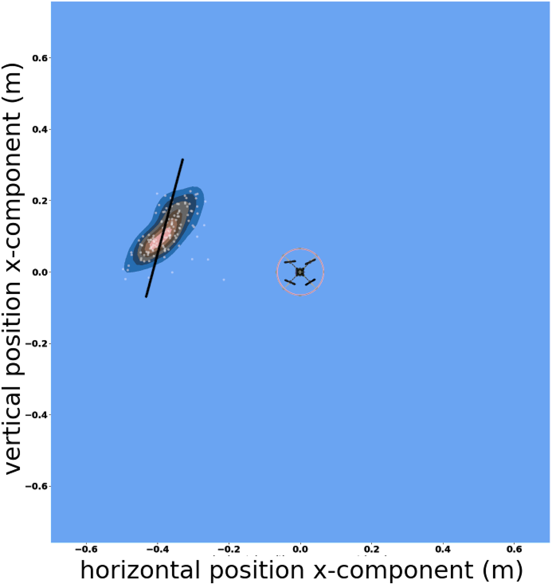
Performance of the machine learning sensory integrator in detecting the position of a surface to the side of the drone. The drone is shown inside the red circle, the wall is the solid black line, the x- and y-axis are position in meters. The white dots show the estimated position of the wall according to the algorithm, with the kernel density plot
22
in blue, black and red constructed from this data. There is strong agreement between these estimates and the actual wall position. The standard error in the estimated position by shortest distance to the wall was

Performance of the machine learning sensory integrator in detecting the position of a surface below the drone. On the x-axis is the true position of the surface below the drone in meters. On the y-axis is the estimated position of the surface according to the algorithm. The standard error on the estimated distance was
The drone was able to distinguish perfectly between the two conditions (wall to the side, floor below) for all examples in the test data set. When estimating the height of the drone above the surface the standard error was
Similarly, the horizontal distance at which performance begins to degrade was not detected, as the algorithm maintained a good performance out to
Surface detection in free flight
For the trials in ground effect, the sound recordings were clearly different, close approach to surfaces can be reliably detected from acoustic signatures. The drone was set to hover at three discrete heights,
Free flight surface avoidance
The drone sucessfully takes action to avoid collisions with planar surfaces. It manoeuvres away from them as they are brought close. Examples of such behaviour can be seen in the in Figure 8 and supplemental movies.

Still images from movie of surface avoidance behaviour. Above: ground avoidance as a horizontal planar surface approaches from beneath. Below: wall avoidance as a vertical planar surface approaches from the right.
Detection of horizontal planar surfaces was reliable. However, surface avoidance of vertical planar surfaces was unreliable. In the majority of trials, we observed premature triggering of the avoidance behaviour, or no avoidance behaviour, when presented with a surface.
Sensing other drones
The Mormoops prototype was always reliably detected by the Crazyflie observer, and both distance (Figure 9) and orientation in the Crazyflie frame of reference (Figure 10) could readily be identified. The reverse scenario was not the case, and no reliable estimates of the position of the Crazyflie by the Mormoops observer could be obtained due to signal being overwhelmed by self-noise. Adjustment of gains and more sophisticated filtering may improve detection capability.
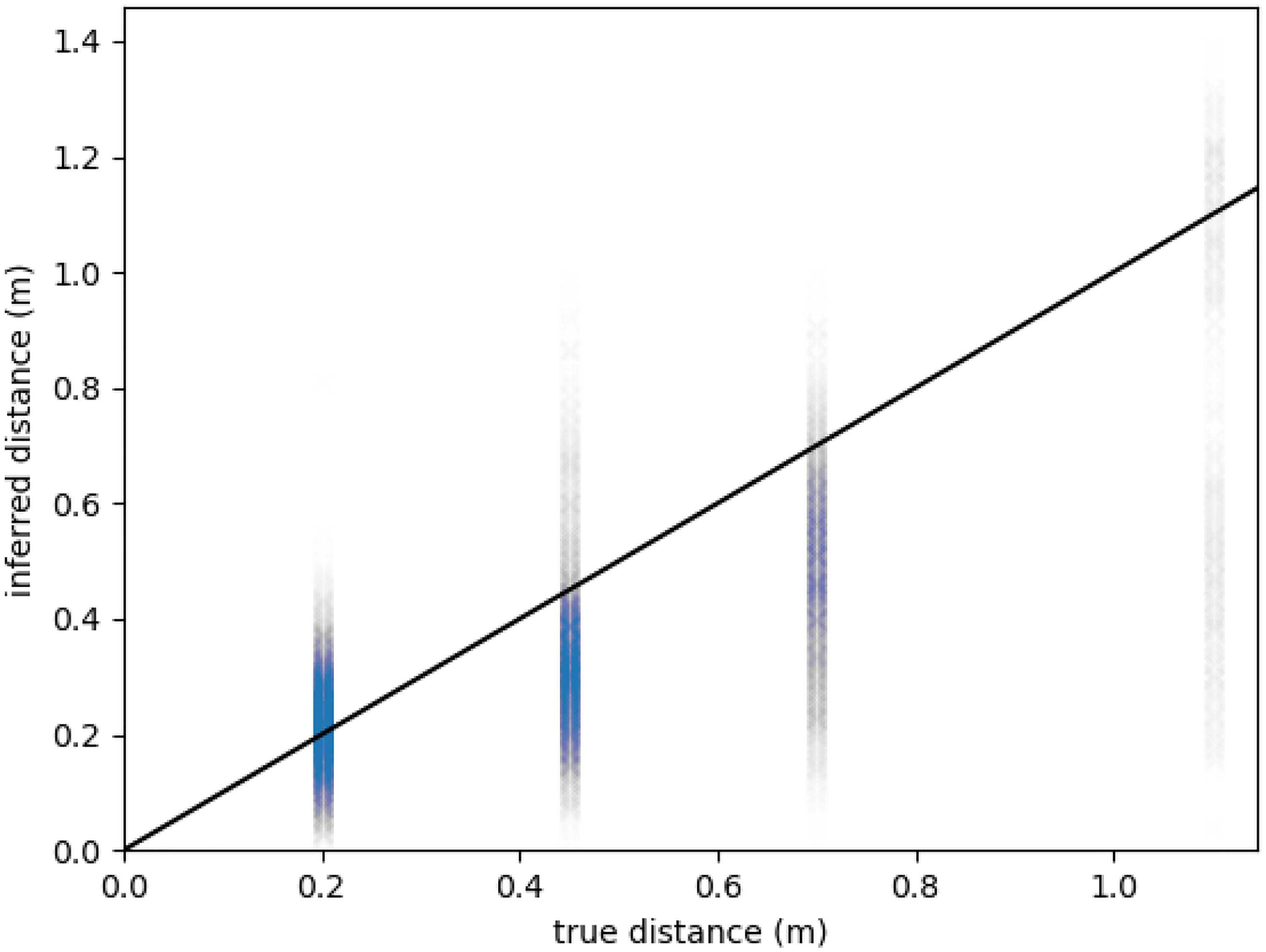
Performance of our machine learning approach when estimating the distance of a target drone from the sensing drone. The x-axis shows the actual distance (ground truth); the y-axis shows the estimate inferred from the microphone recordings and machine learning algorithm. Performance is reasonable for shorter distances, with the error at

Performance of our machine learning approach when estimating the orientation of a target drone (angle relative to forward on the observer drone). The x-axis shows the actual orientation (ground truth); the y-axis shows the estimate inferred from the microphone recordings and machine learning algorithm. Performance is excellent, with a typical error around
The bearing to a secondary drone was always reliably extracted, with a standard error around
Our Mormoops prototype can thus be detected reliably and consistently from a Crazyflie observer when tethered. The reverse was not the case, largely because the Crazyflie is approximately two orders of magnitude quieter than the prototype. No signal was therefore detected for our microphones when gains were configured to avoid clipping on the prototype. In short, the configuration for obstacle avoidance on the Mormoops was not compatible with detection of a secondray, much quieter, drone.
Conclusion
Detection of horizontal planar surfaces is very reliable and robust across modes, tethered, post free flight recording and in drones in flight engaging in surface avoidance. Detection of vertical planar surfaces is reliable while tethered, but far less reliable in the other testing modes. The detection of a larger, louder, more powerful drone from a smaller drone while tethered is possible, and the angle and distance of this drone can be estimated somewhat reliably via acoustic recordings. Detection of the louder drone might be improved by the implementation of motor denoising techniques. 23
For free flight surface avoidance, latency was an issue due to the long chain between sensor systems and flight control (recording to on board microcontroller, to flight control board, to radio, to flight control computer). A reduction in the latency from detection to avoidance could see this evolve into a practical system. At present the latency is around
These trials were conducted under good conditions, indoors and free from wind, which could negatively contribute to performance of both surface detection and avoidance. It is unclear how robust a neural network based approach will be to the additional sounds that occur outdoors, including wind. Unlike physics based approaches which have predictable responses to new conditions (and which allow for those new condition to be incorporated into the physical model), neural network based approaches may not perform stably in conditions that are not in the training data. One approach to this problem would be to intentionally create noise in the training data to simulate wind or external noise in an effort to make the algorithm more robust. Wind would also likely make avoidance manoeuvres more difficult.
The multiplatform capability of our sensor, and sensor integration, packages mean that multi-drone operation with drone identification are achievable with the current system. We have high temporal resolution digital microphones using the specialised audio processing available on the Teensy should frequency range and audio processing be a limiting factor and we have analogue microphone arrays should spatial resolution and multi-direction sampling be critical.
A quiet, light drones capable of supporting these sensors like the Crazyflie could be used for future development should background motor noise be an issue, and a larger, more capable, but louder, like our Mormoops platform could be employed should extra sensors and equipment be needed for drone identification. This capability could be complimented by integrating acoustic surface detection with surface detection using other sensor modalities such as optical flow or pressure sensors.
This work demonstrates novel capabilities of surface detection via self-noise can be extended in exciting new directions including wider sensor integration and in-flight drone detection.
Footnotes
Acknowledgements
We would like to thank Dr. Geoffrey Barrows of Centeye Inc. for useful conversations about drone design and configuration. We would like to thank William Wilson for his efforts in data collection. We would also like to thank the team at the Naval Research Laboratory, particularly Dr. Alisha Sharma, for useful conversations and feedback on the design of neural networks.
Declaration of conflicting interests
The author(s) declared no potential conflicts of interest with respect to the research, authorship, and/or publication of this article.
Funding
The author(s) disclosed receipt of the following financial support for the research, authorship, and/or publication of this article: This work was supported principally by the Defence Science and Technology Laboratory (grant DSTLX-1000143653 to RJB) and, in part, by AFOSR European Office for Aerospace Research and Development (FA9550-19-1-7040 to RJB).