
Abstract
The propulsive wing vehicle is a new concept vehicle, which is driven by a cross-flow fan (CFF) embedded in the trailing edge of the wing. The propulsive wing vehicle is capable of cruising and hovering at high angles of attack with very high aerodynamic force coefficients, and has the potential to become a new type of vertical take-off and landing (VTOL) vehicle. The cruise and hover states of the propulsive wing vehicle are defined, and a numerical model of the two-dimensional propulsive wing is established. Based on the computational fluid dynamics (CFD) method, the rotation of the CFF is simulated by using the sliding mesh technique. The effects of cruise speed, angle of attack and CFF rotation speed on the aerodynamics of the two-dimensional propulsive wing are evaluated, and the mechanism of the propulsive wing flow field changes is revealed. The results show that the propulsive wing has a very high lift coefficient of up to 60 at low speed and high angle of attack cruise, and a high thrust coefficient of up to 40 at low speed and small angle of attack cruise. The aerodynamic force of the propulsive wing fluctuates periodically with the rotation of the CFF, and the amplitude of the fluctuation is related to the vorticity of the CFF blade shedding vortex. In hover, the flow field of the propulsive wing is affected by the geometry and wake deflection into an asymmetric distribution, forming a vortex on each side of the airfoil, and the vortex diameter varies with the CFF rotation speed, which in turn has an impact on the hovering performance of the propulsive wing.
Keywords
Introduction
In response to the demand for high-speed cruise and vertical takeoff and landing (VTOL) capabilities, many new configurations aircraft1–3 have been developed and the related aerodynamic characterization studies4,5 have been conducted. The propulsive wing6,7 vehicle is a new concept vehicle that has emerged over the last decade. The propulsive wing consists of a cross-flow fan (CFF), a main airfoil and a deflector (Figure 1). The CFF was invented in 1893, 8 and its structure consists of a housing and a fan (Figure 2). The air flows radially into the fan from the inlet at the top of the housing, and ejected radially from the airflow channel at the bottom by the compression of the fan. The airflow is essentially in the same plane, therefore the CFF possesses good two-dimensional characteristics. Where radial space is limited, a certain airflow requirement can be met by increasing the spreading length of the CFF. When the CFF is embedded into the wing along the spreading direction, they form a propulsive wing. 6 During flight, the CFF sucks the airflow on the upper surface of the wing, compresses the airflow and ejects it from the flow channel at the trailing edge. While forming thrust, it can also delay the separation of the airflow on the upper surface of the wing, increases the stall angle of attack and improves the aerodynamic coefficient greatly. When the CFF rotates, an eccentric vortex will be formed inside it, where the static pressure is very low, and a part of vortex induced lift9,10 will be given to the propulsive wing under some conditions. However, as the rotation speed of the CFF increases, the strength of the eccentric vortex will also increase, resulting in poor airflow of CFF, increased vibration and noise. Therefore, the study of aerodynamic characteristics of propulsive wing vehicle is indispensable in flight vehicle design.

Propulsive airfoil in reference [6].

Two dimensional structure of cross-flow fan (CFF).
In fact, before the concept of propulsive wing was put forward, some researchers have applied CFF to aircrafts11–13 to delay stall through air flow control. However, the complexity of the wing structure is greatly increased. In 2006, Kummer and Dang6,7 formally proposed the concept of propulsive wing from the perspective of airfoil design (Figure 1). It not only optimizes the wing structure, but also makes full use of the function of airflow control and propulsion of CFF. The relevant CFD simulation 6 and wind tunnel test results 14 show that the propulsive wing vehicle can fly at an angle of attack of up to 40°, and the lift coefficient is as high as 6–7 to realize short takeoff and landing (STOL). However, the thick airfoil and large deflector increase the drag of the propulsive wing vehicle during cruise and limit its cruise speed. With the increase of cruise speed and angle of attack, the air flow is easier to separate. However, during the wind tunnel test in, 14 the velocity of the airflow is only 3.92 m/s, the aerodynamic characteristics of propulsive wing in high-speed cruise state are not considered.
Based on the researches of the CFF15–18 and the CFF vehicles with hovering capability,19,20 Fulton designed a new propulsive airfoil 21 (Figure 3). Through conducting the CFD simulations and hovering tests (Figure 4), the cruise and hover functions of the propulsive wing vehicle were verified, and the propulsive wing vehicle has the potential to become a new type of vertical takeoff and landing vehicle. However, the CFD analysis of the propulsive wing vehicle was carried out in a steady-state, which can reduce the calculation time, but cannot simulate the changes of the transient flow fields of the propulsive wing and the CFF. This method is insufficient to support an in-depth analysis of the variation of propulsive wing aerodynamics and the characteristics of the flow field. In conclusion, for the propulsive wing vehicle, which is a new concept vehicle, it is necessary to conduct all-round aerodynamic characteristics research on its key flight states, and have a clearer understanding of its flow field structure and variation laws, so as to provide a basis for vehicle design in the future.

Propulsive airfoil in reference [21].
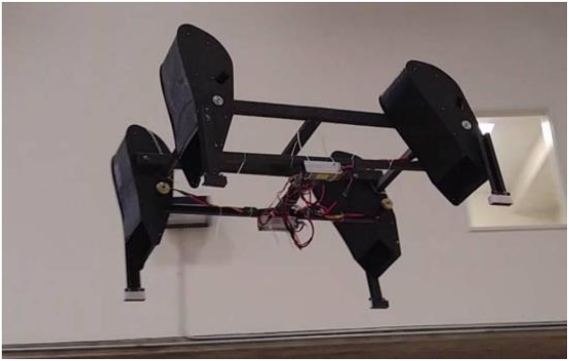
Hovering test of propulsive wing vehicle. 21
With the continuous improvement of computer performance, the application of CFD methods in the study of aircraft aerodynamic characteristics is becoming more and more mature, and much related research work22–24 has been carried out. For the propulsive wing, its structure is different from the conventional wing, and there is a high-speed rotating CFF inside the wing, which requires a lot of computational costs if the 3D model is directly simulated. In the past decade, many scholars had used the two-dimensional simulation method to study the aerodynamic characteristics of fan-wing,25–28 and the fan-wing has much in common in geometric structure and working principle with the propulsive wing. Considering that the CFF has very stable two-dimensional characteristics,8,29 this study adopts CFD method to study the aerodynamic characteristics of the two-dimensional propulsive wing under cruise and hover states, to explore the variation law of the aerodynamics of the airfoil, and to make a more in-depth analysis of the aerodynamic changes by combining the structure and variation mechanism of the airfoil flow field.
The other parts of this study is organized as follows: In Section “Problem definition and numerical method”, the cruise and hover states of propulsive wing vehicle are defined, the calculation model of two-dimensional airfoil is given, and the numerical calculation method of airfoil flow field of two-dimensional propulsive wing is established and verified. In Section “Analysis of aerodynamic characteristics of two-dimensional propulsive wing”, the effects of cruise speed and angle of attack on the aerodynamic performance of propulsive wing in cruise are studied, the reason for the high aerodynamic coefficient of propulsive wing is explained, and the periodic variation characteristics of aerodynamic force are analyzed; then, the influence of CFF rotation speed on the hovering attitude angle of the propulsive wing is studied, the aerodynamic performance and flow field structure characteristics of the propulsive wing in hover are analyzed. In Section “Conclusions”, the main conclusions of this study are given.
Problem definition and numerical method
In this section, the problem studied is defined, and the calculation model of two-dimensional propulsive wing is given. Then the numerical method for the calculation of airfoil aerodynamic forces is established, and the feasibility of the numerical method is proved through relevant verification.
Definition of research problem
Firstly, the cruise and hover states of propulsive wing vehicle are defined, and the relevant dimensionless formulas and two-dimensional airfoil parameters are given.
The three-dimensional model of the wing of a practical propulsive wing vehicle is shown in Figure 5, which is composed of main airfoil, CFF, deflector and side plates. The cruise state of the propulsive wing vehicle is similar to that of a conventional vehicle. The included angle between the airfoil chord and the incoming flow is angle of attack

Three dimensional wing model of propulsive wing vehicle.

Flight states of propulsive wing vehicle. (a) Cruise state, (b) Relative static state, (c) Hover state.
When the propulsive wing is in a relative static state with the incoming flow velocity
In cruise state, the lift and drag coefficients are as follows:

In, 21 the hovering of propulsive wing vehicle has been realized. Therefore, the model used in this study is based on the model in, 21 and the parameters of CFF are changed. The definition of geometric dimensions of propulsive airfoil and CFF are shown in Figure 7, and the main parameters of propulsive airfoil and CFF are listed in Table 1.

Definition of geometric parameters of propulsive airfoil and CFF. (a) Propulsive airfoil parameters, (b) CFF parameters.
Parameters of propulsive airfoil and CFF

Numerical method
In this study, CFD method30,31 is used to calculate the flow field and aerodynamic force of two-dimensional propulsive wing. In this section, the numerical method and application process of CFD software ANSYS Fluent in numerical simulation are briefly given.
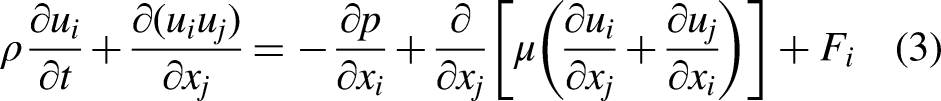
The unsteady flow field of two-dimensional airfoil is calculated in this study, therefore 2-D Navier-Stokes equation is selected as the main governing equation of unsteady incompressible flow field of propulsive wing:
The finite volume method is used to discretize the flow field in the study, the convection term is discretized by the second-order upwind scheme, and the Semi-Implicit Method for Pressure Linked Equation (SIMPLE) algorithm
32
is used to solve the control equation. The turbulence is modeled by the realizable
The setting of calculation zone, boundary conditions and coordinate axis of numerical simulation in this study are shown in Figure 8. The fixed two-dimensional Cartesian coordinate system is adopted. The size of computational domain in cruise state is

Computational zone and sliding mesh. (a) Calculation zone division of cruise state, (b) Calculation zone division of hover state, (c) Rotating and static zone, (d) Rotating zone mesh, (e) Boundary layer mesh.
Validation
Grid and time step validation
To ensure the reliability of the calculation results and reduce the error caused by the numerical method,35,36 the grid and time step used in the numerical calculation are verified. By changing the mesh density in the rotating zone, meshes of different sizes are generated to calculate the aerodynamic force of the propulsive wing during cruise. The boundary layer mesh settings of these grids are the same.
Aerodynamic coefficients of propulsive wing with different mesh density

With the grid division scale of case 2, the process of one circle of the CFF rotation is divided into three time steps: 72, 360 and 720, each time step is 1.389e−5, 2.778e−5 and 1.1112e−4 s, respectively. The calculation results of different time steps are shown in Table 3. Taking the values of case 6 as baseline, the errors of lift and drag coefficient of case 7 and case 6 are 0.36% and 0.69%, respectively, and the errors of case 5 and case 6 are 8.3% and 7.9%, respectively. Considering the calculation efficiency and accuracy, the time step of case 6 is selected for simulation, that is, one time step is 2.778e−5 s.
Aerodynamic coefficients of propulsive wing with different time steps

Wind tunnel test validation
Previously, the research group conducted wind tunnel tests on the propulsive wing model in reference
7
and measured the aerodynamic forces of the propulsive wing under different working conditions. In this study, some experimental values (

Test system of validation model.

Two dimensional structure of validation model.
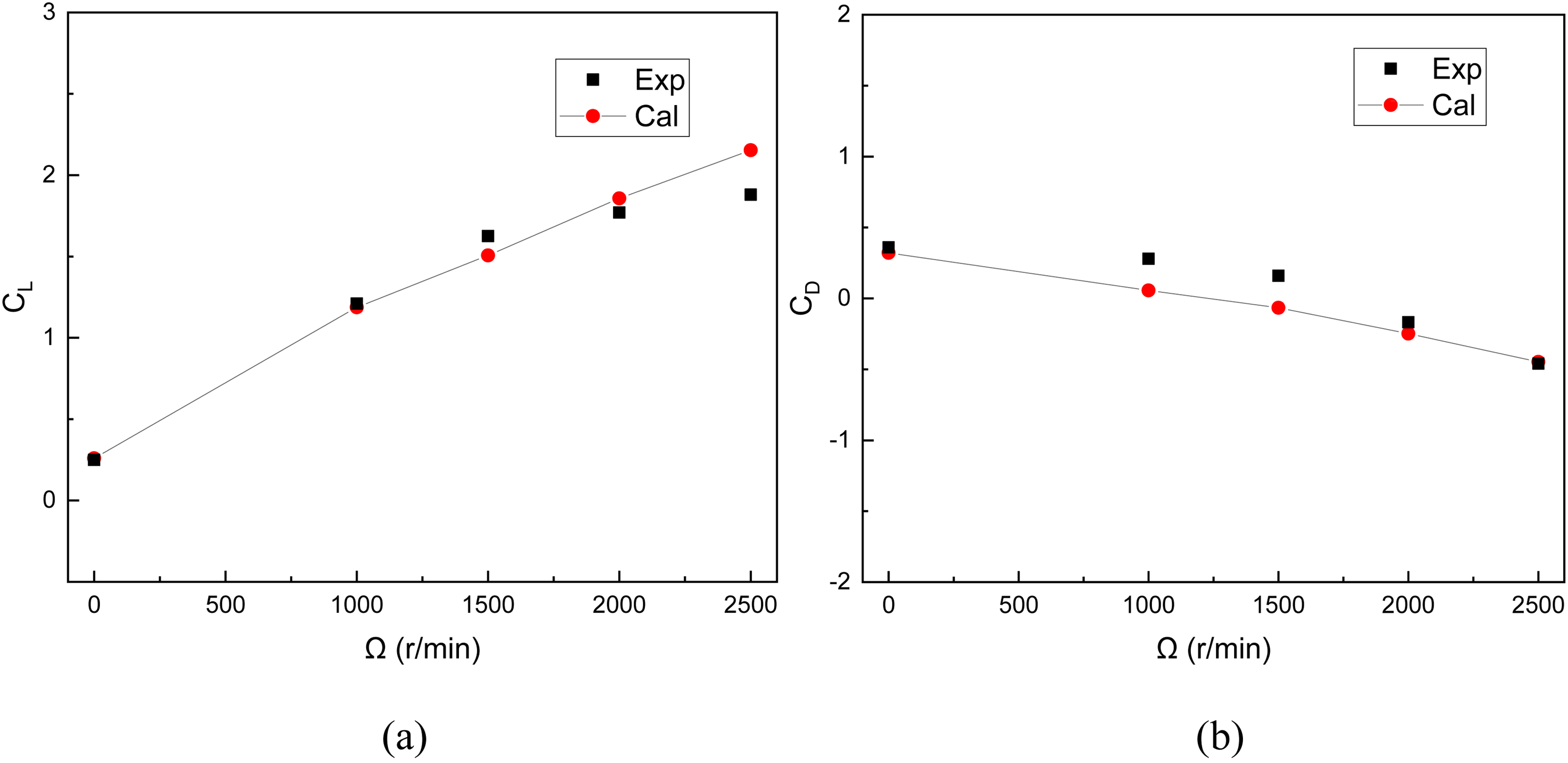
Calculated and experimental values of the validation model. (a)
Analysis of aerodynamic characteristics of two-dimensional propulsive wing
As mentioned above, the propulsive wing vehicle does not need additional power devices, it can generate horizontal thrust and vertical lift on the wing only by the rotation of CFF. The propulsive wing vehicle can realize cruise and hover at high angle of attack, and has a very wide application prospect. In this section, the numerical methods established above are used to simulate and analyze the aerodynamic characteristics of two-dimensional airfoil in cruise and hover, respectively. The variation laws of airfoil aerodynamic forces with angle of attack, cruise speed and CFF rotation speed are studied, and the reasons for the variation of airfoil aerodynamic force are explained in combination with the variation mechanism of airfoil flow field in different states.
Cruise state
In this section, CFD method is used to study the aerodynamic characteristics of two-dimensional propulsive wing in cruise. Firstly, the variation law of airfoil aerodynamic force with angle of attack and cruise speed is analyzed; Then, through the comparative analysis of the flow field of the propulsive wing at different cruise speeds, the reason for the high aerodynamic force coefficients of the propulsive wing at low speed is explained; Finally, the aerodynamic characteristics of propulsive wing are deeply analyzed from the complex periodic variation of aerodynamic force. At the same time, the change mechanism of airfoil flow field in cruise is explained. The working speed of CFF in cruise is 6000 r/min, the cruise speeds are 3, 5, 7, 10, 15, 20 and 30 m/s, respectively. And the Reynolds number varies from 102,688 to 1,026,880 correspondingly. The angle of attack varies from 0° to 40° with an increment of 15°.
Change of aerodynamic force
In this study, the aerodynamic parameter formula (1) of conventional wing is used to represent the aerodynamic performance of propulsive wing, which can intuitively show the unique performance of propulsive wing.
The variation of aerodynamic forces and coefficients of propulsive wing with cruise speed

Variation of propulsive wing aerodynamic forces and coefficients with
The high speed rotation of the CFF will form thrust on the propulsive wing. It can be seen from Figure 12(d) that the thrust coefficient(
Figure 12(e)–(h) show the variations of aerodynamic forces and coefficients of the propulsive wing at
The instantaneous static pressure clouds, streamlines and vorticity contours at

Instantaneous static pressure clouds and vorticity contours of the propulsive wing when

Instantaneous static pressure clouds and vorticity contours of the propulsive wing when
Combined with the vorticity contours in Figures 13 and 14, it can be found that in the low speed state, the bound vortex on the upper surface of the main airfoil flows into the CFF along the junction of the airfoil and the CFF, and then is compressed and ejected. In the high speed state, the vorticity on the upper surface of the main airfoil increases, and due to the blockage of the separation bubble, this part of the vortex can only flow from the middle of the CFF inlet, occupying part of the airflow inlet, which in turn leads to the reduction of the CFF inlet flow quality. While the vortex flow occupies the air flow channel of the fan, the CFF blade shedding vortexes mixed in the vortex flow, the vortex groups that accumulate at the bottom of the deflector are not replenished, causing a decrease in propulsive wing performance.
Moreover, as shown in the streamlines of Figures 13 and 14, the streamline forms a stagnation point
40
when it flows over the airfoil surface, and this point has a velocity of 0. When
Periodic variation of transient aerodynamic force
In actual flight conditions, the aerodynamic forces of the propulsive wing fluctuate constantly with the high-speed rotation of the CFF. In order to have a deeper understanding of the aerodynamic performance of the propulsive wing, the periodic variations of the aerodynamic forces are analyzed from the perspective of transient.
The variations of the aerodynamic coefficients of the propulsive wing in the time domain at
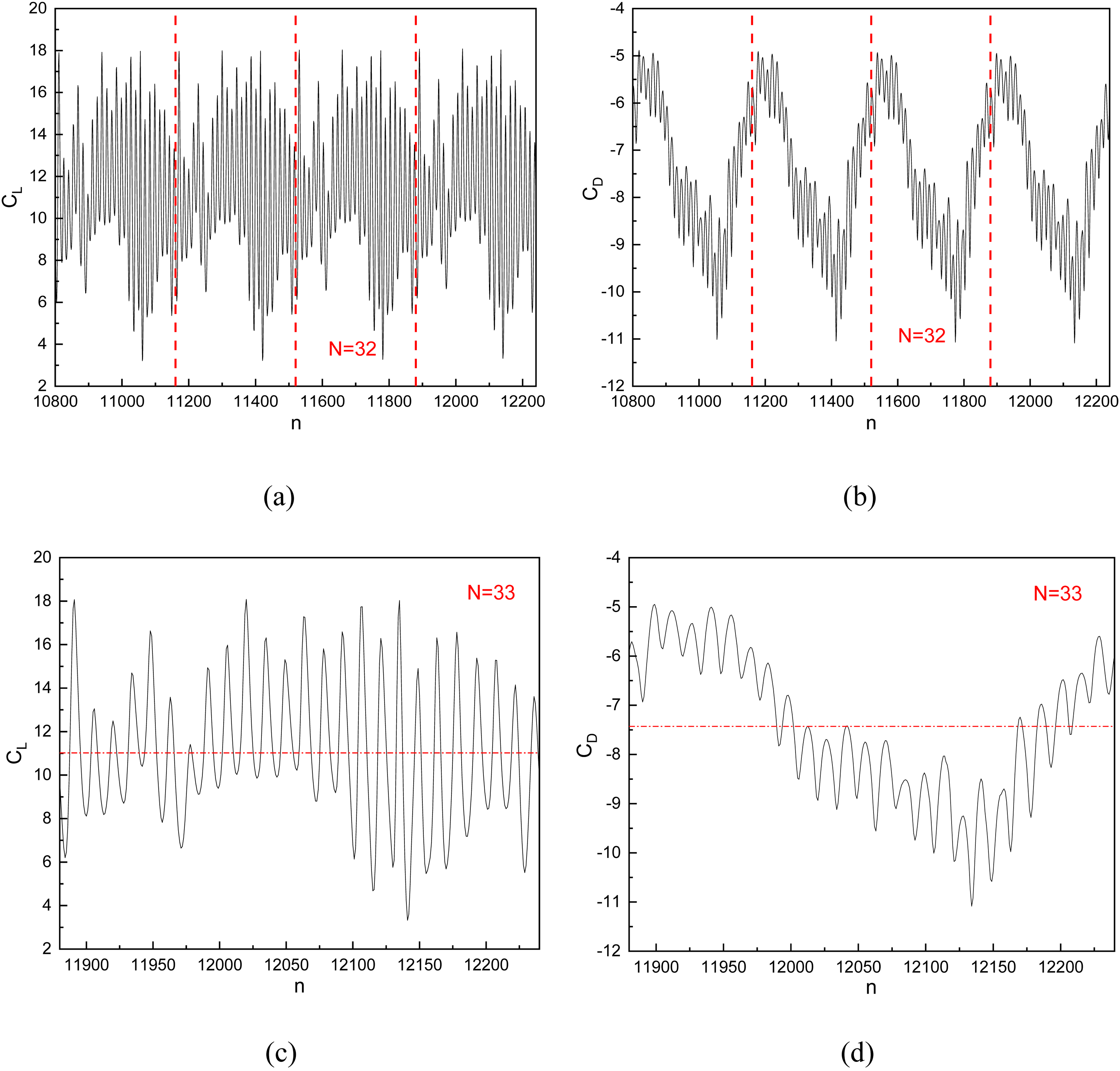
In order to explore the reasons for the unequal amplitude of aerodynamic fluctuation of the propulsive wing, the change of aerodynamic force of the propulsive wing and its components around 2/25 period is shown in Figure 16, and the corresponding steps are
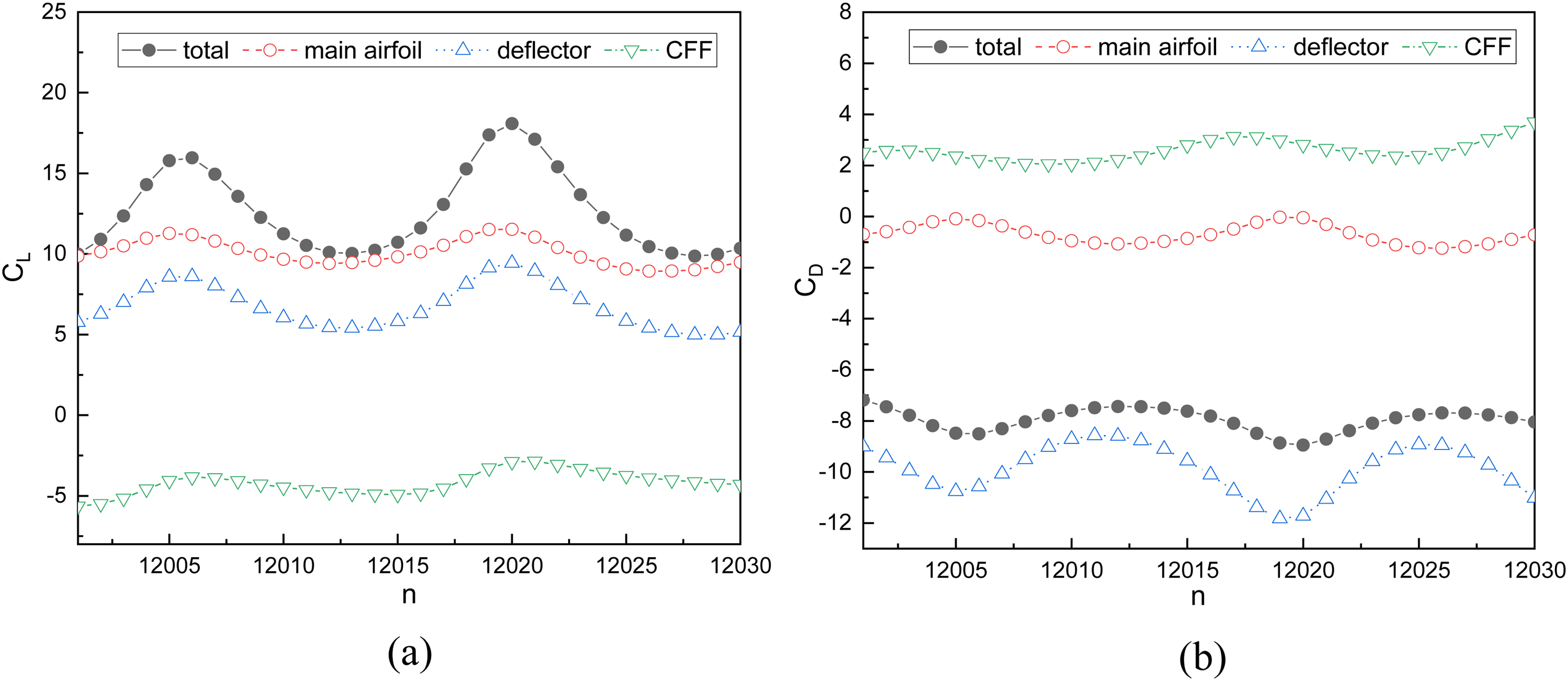
Transient
Combined with the instantaneous static pressure clouds and vorticity contours41,42 of the propulsive wing in Figures 17 and 18, we can analyze these phenomena more deeply. Comparing the five instantaneous static pressure clouds in Figure 17, it can be found that there is a high pressure zone at the bottom of the deflector, and the pressure difference between the upper and lower sides forms the lift on the deflector. As the CFF rotates, the pressure in this zone is constantly changing, causing fluctuations in lift. In the vorticity contours of Figure 18, we have made some annotations, red vortices are positive, denoted by Pi, and blue vortices are negative, denoted by Ni. Where, i = 1, 2… represents the order of the vortexes shed on the CFF blades. In Figure 18(a), P1 merges with the positive vortex group accumulated at the bottom of the deflector, resulting in an increase in vorticity here, a decrease in airflow velocity and an increase in static pressure, which acts as a lift enhancement to the deflector. In Figure 18(b), the counterclockwise N1 merges with the positive vortex group at the bottom of the deflector, dissipating part of the vorticity and leading to an increase in the airflow velocity, which causes a decrease in lift. In Figure 18(c), the influence of N1 on the deflector gradually disappears and the lift reaches the trough, while P2 is just flowing to the bottom of the deflector and is about to merge with the vortex group. In Figure 18(c)–(e), the lift of the deflector gradually rises to another crest as P2 merges with the vortex group. Meanwhile, the change of vorticity of blade shedding vortex Pi causes the change of lift force fluctuation amplitude.

Instantaneous static pressure clouds of the propulsive wing when

Instantaneous vorticity contours of the propulsive wing when
Hover state
In hover, the airflow velocity of the flow field is small, and the wake of the CFF will have a large impact on the performance of the propulsive wing. In order to have an in-depth understanding of the hover performance of the propulsive wing, the aerodynamic characteristics of the two-dimensional propulsive wing in the hover state based on CFD method will be analyzed in this section. According to the previous definition of the hover state of the propulsive wing vehicle, the rotation of the CFF will still form a horizontal force
Change of the hover angle
Firstly, the relative static state in Figure 6(b) is simulated to find the horizontal force
The variation of horizontal force

Horizontal force

Variation of propulsive wing hover angle
The streamlines of the propulsive wing at

Streamlines and vorticity contours of the propulsive wing when
Change of aerodynamic force
The hover attitude of the propulsive wing is derived from the hover angle

Variation of aerodynamic force of propulsive wing with CFF rotation speed in hover. (a) Vertical force
Structure of hovering flow field
According to the above analysis, the flow field in the hover state of the propulsive wing differs greatly from that in the cruise. In order to have a more comprehensive understanding of the hover state, the flow field distribution of the propulsive wing at

Streamline and vorticity contour of the propulsive wing when
Conclusions
In this study, CFD method adopting the sliding mesh technology is used to simulate the flow field of the two-dimensional propulsive wing, and the feasibility of the numerical method is proved by comparing the calculated values of the aerodynamic forces of the propulsive wing with the wind tunnel test data. Based on this numerical method, the aerodynamic characteristics of the two-dimensional propulsive wing under cruise and hover states are studied. The results show that:
In cruise state:
The aerodynamic force coefficients of the propulsive wing are related to both the angle of attack and the cruise speed. The lift coefficient increases with the increase of angle of attack and decreases with the increase of cruise speed, and the lift coefficient is as high as 60 at low speed and high angle of attack. The thrust coefficient decreases with the increase of angle of attack and cruise speed, and the thrust coefficient is as high as 40 at low speed and small angle of attack. The aerodynamic force of the propulsive wing changes periodically with the rotation of the CFF. The period of aerodynamic force is consistent with the rotation period of the CFF, the fluctuation frequency is consistent with the rotation frequency of the CFF blade, and the amplitude of the fluctuation is related to the vorticity of the shedding vortex of the CFF blade. The hover angle The vertical aerodynamic force of the propulsive wing increases with the CFF rotation speed, but there is a critical speed. Exceeding the critical rotation speed will lead to a sudden increase in the torque of the CFF. The hovering flow field of the propulsive wing becomes an asymmetric structure due to the propulsive wing geometry and the wake deflection. A large diameter vortex is formed on the side of CFF inlet, and a small diameter vortex is formed on the lower surface of the airfoil. The diameter of the vortex changes with the CFF rotation speed, causing the movement of the stationary point on the airfoil surface, which in turn causes changes in the aerodynamic force of the propulsive wing.
In hover state:
Footnotes
Declaration of Conflicting Interests
The author(s) declared no potential conflicts of interest with respect to the research, authorship, and/or publication of this article.
Funding
The author(s) received no financial support for the research, authorship, and/or publication of this article.