
Abstract
Autonomous landing is a fundamental aspect of drone operations which is being focused upon by the industry, with ever-increasing demands on safety. As the drones are likely to become indispensable vehicles in near future, they are expected to succeed in automatically recognizing a landing spot from the nearby points, maneuvering toward it, and ultimately, performing a safe landing. Accordingly, this paper investigates the idea of vision-based location detection on the ground for an automated emergency response system which can continuously monitor the environment and spot safe places when needed. A convolutional neural network which learns from image-based feature representation at multiple scales is introduced. The model takes the ground images, assign significance to various aspects in them and recognize the landing spots. The results provided support for the model, with accurate classification of ground image according to their visual content. They also demonstrate the feasibility of computationally inexpensive implementation of the model on a small computer that can be easily embedded on a drone.
Keywords
Introduction
Regulation for drones are becoming increasingly characterized by technology-facilitated applications as the drone use is rapidly expanding to serve in various applications of agriculture, scientific research, surveillance, search and rescue, infrastructure inspection and management, environmental monitoring and law enforcement. 1 Computational advancements and prodigious amount of condition monitoring data can be the key drivers of the future drone regulations, while the need for autonomous landing processes and growing acceptance of contemporary complex computer systems are also noted. Administrative authorities have been imposing restricting drone regulations with an attempt to secure safe and sustainable operations to assure public safety and privacy on condition that less restricted drone operations are available.2,3 As these unmanned aircraft system regulations urge sustainable and secure drone operations to protect the people’s safety, one can reasonably assume that the modern drones will have to be individually safe, allowing both legislation and end-users to provide drone reliability.
Previous research in the unmanned aircraft system (UAS) literature has introduced several frameworks such as computer vision aided positioning system, 4 autonomous tracking and landing control on an autonomous vehicle, 5 marker recognition on a landing pad, 6 vision analysis for automatic landing, 7 autonomous flight system with marker recognition, 8 or even illegal landfill detection. 9 Akbari et al. 10 reviewed applications related to drones and image recognition, and categorized them into various groups such as remote sensing, autonomous navigation and the sensed environment applications. As pointed out by them, the field still need to develop image recognition information for uncharted applications.
A major point of improvement between the drone safety and computational product development is the involvement of analyzing visual landing location with fully connected multi-layer perceptrons. Particularly, convolutional neural networks (CNN) have received much attention in analyzing large-scale imagery which has recently become possible due to the advancing technologies.11–15 In particular, there is a significant potential in the advance of CNN based visual recognition for drones, which can serve detecting locations of interest that can facilitate a landing, or even a crash, without any human injury or fatality. With CNN models becoming more of a commodity in the vision recognition, 15 they could let better compliance standards of drone activities by tracking safe landing locations and providing an easier development for operational process. It is therefore increasingly evident that these models will continue to be a critical component of drone situations, especially where the critical in-flight anomalies are experienced.
Drones have some characteristic safety drawbacks that are relatively existent in most UAS systems. Therefore, they need to be designed with a level of situational awareness and the “sense and avoid” capabilities that match those of manned aerial systems. 16 However, drones are usually under real-time human control with no on-board pilot and operated from a remote terminal. Therefore, their size result in a lower weight and a smaller extent than a peer manned aircraft, allowing only smaller embedded systems to be run. This means that, in spite of having a smaller on-board system computer, they must be able to respond with appropriate avoidance maneuvers to maintain safety 16 and to deal with risk perceptions that are generally elevated by ever increasing societal acceptance in company with the complex human behavior with machine interface and operational roles. 17
For image recognition and visual recognition for autonomous drone landing, the unmanned systems in smaller sizes can only tolerate a small computer mounted on the vehicle which is also expected to track the health state and guidance for landing.18,19 When there is a safety-critical condition, it is expected from this computer to determine the best course of action for the aircraft to minimize the probability of fatalities. This means a significant challenge for automated location recognition framework. Considering this issue in particular with CNN based visual recognition, the literature has not yet been clarified on the development of resource intensive application and its interface with the accompanying safety duties. Consequently, there is an incomplete picture of the way novel imagery landing location frameworks are developed. Against this background, the main purpose of this study is to investigate the role of CNN based visual landing recognition while considering the distinctive drone properties (see Figure 1). The study also aims to determine safety factors that may be associated with with the automatic location spotting.

Graphical Abstract of Drone Image Processing.
To further understanding, this research has the following objectives:
To find good landing spots that can facilitate an emergency landing or even a crash without casualties. To analyze a class of input image taken during an ongoing flight and output a class, or simply a probability of classes, that best describes whether the location is suitable for emergency landing. To develop a conceptual framework of a machine vision approach for detecting areas by outlining theoretical underpinnings and analyzing related research and construction schemes. To test the proposed model empirically by grabbing images from the camera mounted on drone (SafeEYE lab Bektash et al.
18
), which are monitored from various test flights where the primary focus was to provide images of a variety of terrains.
Because of the limited existence of on-flight pictures on previous research settings, 18 this study chose to further advance the autonomous location spotting framework with novel imagery with detailed surface scenes and examine whether CNN structure containing more visual information provide a strategic advantage for safety related operations. This means that this work has a further potential to become a safety enabler for a wide variety of drone applications.
The rest of the article is structured as follows: First, the extant literature on autonomous drone landing, vision recognition and convolutional neural networks are reviewed with an attempt to represent the theoretical core of the paper. This is followed by an introduction of the research methodology with procedures used in the work. A case study is then offered to analyze as the research is expected to read-through to particular context introduced in the methodology section earlier. The results of the research are then summarized with the findings of the study in the form of descriptive statistics. Finally, in the conclusion section, implications, limitations, and directions for future studies are laid out.
Background and Related Work
Recognition and detection of defined objects on captured scene images have been well-known challenges, even supposing that the literature have brought many solutions to existing problems. The growth of image recognition algorithms is a determining factor to overcome these issues. A number of works have been introduced to make picture processing studies possible on drone systems. Current strategies have used various designs such as using markers, 8 features classifiers and detectors,20,7 and both static 21 and dynamic picture recognition. 22 Further works of autonomous drone landing can be regarded as a multifaceted construct consisting of various dimensions. Those of using image processing algorithms such as above-mentioned ones typically aims to find a spot to safely and securely land the drone. However, they should be accompanied with other autonomous actions such as malfunction detection and guidance for landing. 18 The explicit analyses of visual interpretation and image classification along with their relationship to these autonomous actions help provide evidence showing that the location recognition is feasible to optimize and can provide safety to considerably increased complexity of drone operations.
Definitions of on-board vision landing systems focused on landing on a known area rather than the strategies in unfamiliar and imprecise conditions. In that respect, Kong et al. 23 enounced the UAS landing on controlled zones as a well-studied research area by outlining the common use of motion algorithms and the requirement for structured landing settings. While fixed-wing UAS autonomous landing on a known area is commonly practiced on a runway,24–26 drone and rotary-wing UAS studies concentrate on marker based tracking methods for landing. 23 Traditionally, a helipad of a known shape is used for target detection. Drones automatically updates landing target parameters based on visual markers and follow a path to the helipad. For instance, Saripalli et al. 27 provided the foundation for vision-based landing target detection on real-time which leads the act to a board behavior based controller to follow a path to a helipad of with a H-shaped marker. In order to achieve autonomy in such a scheme, on-board sensors might have needed to cope with UAS’s processing power which was generally limited due to low weight capacity. To deal with this, Wenzel et al. 28 proposed a tracking approach that uses commodity consumer hardware. More recently, some researches appear to agree that image frames can be processed by a marker processing framework which includes various stages such as image rectification, conversion into a binary image and vision aided landmark recognition.29,30 Similarly, Sudevan et al. 31 fused speeded up robust features detector and fast approximate nearest neighbor method for landing on a stationary target. Additionally, Saavedra-Ruiz et al. 32 presented a monocular visual system, using a software- in-the-loop for autonomous landing on a predefined landing pad and Cabrera-Ponce and Martínez-Carranza 33 used a flag posed on a pole to locate the landing platform nearby.
Even though marker recognition procedures can perform automatic aircraft landing stationary target, further processes are needed to achieve accurate landing on a moving platform. Besides, advancing technologies made possible successive waves of new sensors: from basic signal providers to complex camera systems. To process these multi-sensor information, Yang et al. 34 came up with a practical framework in which data from various sensors of rotary-wing UAS is analyzed for reliable navigation information as the aircraft approaches to the landing deck on a moving marine vehicle. Considering multi-sensor information, more complex data need a systematical algorithm rather than the traditional data-processing methods used before. Correspondingly, to fuse data from multiple sensors with an attempt to provide the reliable information for navigation, Yang et al. 34 developed an extended Kalman filter using a series of measurements observed over time. This method can provide unknown variable estimations which are in general more precise than the ones with a single measurement alone.
Landing on mobile marine vehicle is also supported by additional findings of Venugopalan et al. 5 who proposed an autonomously control algorithm to land on a pad placed over an autonomous kayak, Polvara et al. 35 who aims to address the landing pad as the deck of a ship and Weaver et al. 36 who create a scaled-down model of ship landing of an UAS onto a mobile unmanned surface vehicle. These studies had a more or less explicit perspective on harsh condition landing prevalent in the marine environments as a result of winds and currents causing the stationary landing target to rock and drift. In a like manner, autonomous landing on unknown vehicle positions is extended to the implementation of autonomous approach on a car moving. 37 Although the vehicles in which these studies are conducted are mobile and operate in unknown positions, the aircraft still navigates to a known deck or landing pad rather than unstructured and unknown harsh 3D surroundings. This gap is common not only for these schemes, but also the most of other methodologies using a known marker or shape.
In response to this gap, Johnson et al. 38 tackled the concept of soft-landing capability in unknown and hazardous terrain, arguing that it will allow exploration of previously inaccessible environments with strong scientific importance. Scherer et al. 39 also critiqued the inability of UAS to identify and verify landing zones and approach paths by using not only plane fitting but also various factors such as wind direction, terrain and skid interaction, rotor and tail clearance, and approach, abort and ground paths. While their algorithm could incorporate these factors to fulfill autonomous landing at unprepared sites, their framework and results were based on a full-scale helicopter which selects its own landing sites. For small-scale micro air vehicles, especially those capable of operating outside line-of-sight, findings by De Croon et al. 40 highlights the significance of optic-flow based slope estimation for relatively fast maneuvers.
The models up to here allowed successful estimation of landing location; however, extracting local and position-invariant features has a potential role in unknown environments. Nguyen et al. 41 found this to be true in their study which included a convolutional neural network to extract trained features from captured images. However, their algorithm was based on estimating a marker’s location with visible light camera sensor rather than to process field images for emergency landing. A similar work based on deep reinforcement learning, a hierarchy of Deep Q-Network, is used for landmark detection by not only managing with low-resolution landmark images from a mounted camera and also providing higher performance than human pilots in some conditions. 42 A later work of image recognition technology in emergencies by Yang et al. 43 critiqued the drone navigation methods relying on global positioning system signals and introduced a landing procedure that can estimate drone’s position by creating a grid map of the environment to decide on the most suitable landing location via a filtering algorithm. Rojas-Perez et al. 44 implemented CNNs for automatic detection zone for UAS in urban environments with a public dataset and synthetic data. In a further work, Osuna-Coutiño and Martinez-Carranza 45 extended the use of the CNN-based approach processing a single image seeking to interpret areas where the human-made structures are observed. Lopez-Campos and Martinez-Carranza 46 advanced the synthetic data application by generating photogrammetric aerial-images from photo-realistic scenes.
It is increasingly evident that the innovations on image processing will continue to be a critical strategy for autonomous emergency landing. One can also expect that these vision-based interactions will also become a key criterion for supporting elements of safety and can collaborate with them. Recent works has begun to safety challenges and focused on third-party risk associated with UAS operations such as the people on the ground with no involvement in the operation.47,48 Similar efforts were devoted by Lum and Waggoner 49 to remove the threats to human safety from mid-air collisions, as well as the ground strikes. To enable the tracking of fatality rates caused by crashes over time, Melnyk et al. 50 used historical data which gives key insights to enable operational safety in civilian airspace. While initial considerations relating to third party risks were around airports such as crash, individual risks, and societal concerns, 51 later studies tackled the risk management of unmanned flights over inhabited and populated areas.52,53 Despite these works, little is known about the image processing for automated landing of larger drones (> 7 kg) in unstructured environments. Consequently, there is an incomplete picture of the way image characteristics are accurately analyzed under these conditions. That is why, this research attempts to identify key development stages of the image processing and ties them to safe landing and recovery of larger drones. Essentially, the research responds to the call for a novel approach about the information processing and distributed communication nodes in location recognition and draws inspiration from ever increasing regulations which have stressed the need for designing individually reliable drones that will enable end-users to ensure safe, sustainable, and secure operations.
Methodology
This section provides information on the proposed research method and CNN procedures for the application of image detection. The method is a series of layers which helps extracting the image features and respond to the final fully connected network for classification. The layers are described in the following subsections.
CNN architecture
The first layer of a CNN, also known as the input layer, consist of artificial input neurons that bring the initial imagery data into the network structure for the subsequent layers. These initial data were available from a database of 10,000’s of images captured from the SafeEYE lab that has been mounted, integrated, and flown in a number of test flights on a DJI Matrice 600 drone 18 (see Figure 2). There were a number of test flights that had been conducted with the SafeEYE, primarily to collect data and to test the machine vision approach for the detecting areas of interest for landing or a crash without any human injury or fatality. Most prominently, three campaigns with a total of approximately 12 hours of flight were conducted in two sites in Denmark, an emergency responder training facility at Rørdal, Aalborg and a military training compound Brikby consisting of about 30 empty houses, located at Oksbøl Barracks. Both sites are in Denmark. These areas were also used to accomplish the task of flight tests with Home Guard personnel acting as city residents. Having both rural and urban ground textures while legally being an urban area was the reason why these sites were selected. Besides, the military field had an airspace restriction zone, which allowed the drone to capture images up to an altitude of 150 m.
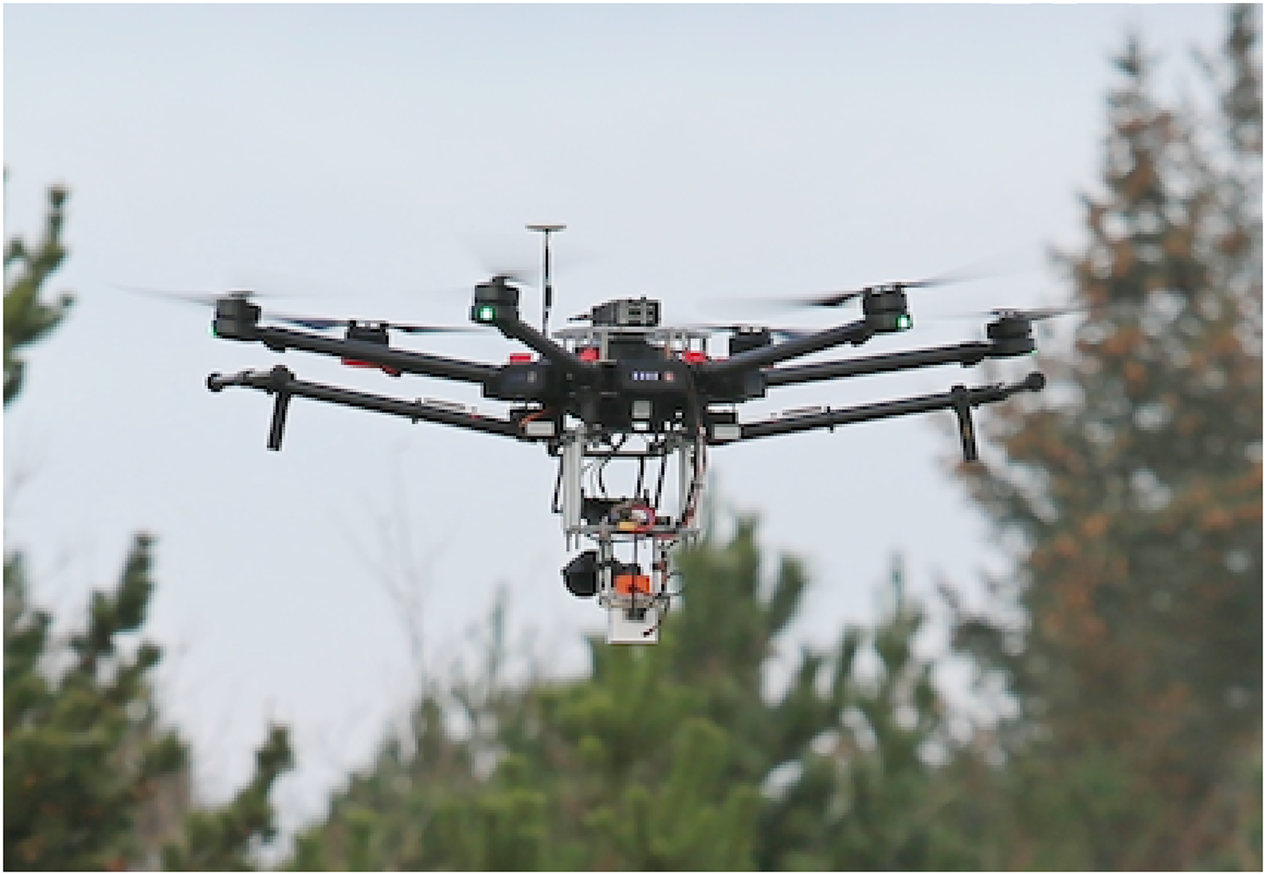
SafeEYE lab is mounted on a DJI M600 drone. The white box at the bottom is SafeEYE lab, with an extra IMU on top (orange). Behind SafeEYE lab is a standard X5 camera. The payload radio is mounted on the top of the aircraft. The image is from Oksbøl on December 4, 2019.
To perform in such a large-scale image processing, this study proposes the use of a feed-forward neural network type in which the neurons are able to reply to some surroundings in the coverage range. Original structure (the LeNet architecture - LeNet5 - 1990s) was first introduced by LeCun and pioneered the CNNs which propelled the field of Deep Learning. 11 The methodology uses a slightly modified version of the LeNet architecture and classifies the input images into two categories: “landing fields” and “not landing fields”. The reason is that the structure is straightforward, relatively small in terms of memory footprint and could even run on a single-board computer, making it ideal for the use of SafeEYE lab.
A CNN usually receives an order 3 tensor input image with rows, columns, and channels which then sequentially proceed a series of processing steps, commonly known as layers.
54
The abstract description of the CNN architecture can be given as:


Architecture of LeNet, image modified from LeCun et al. 11
Convolution
The first building block in the framework is a convolution operation in which the feature detectors serves as CNN’s filters. In this stage, a fairly simple 2D convolution operation begins with a kernel, a matrix of weights. Then, this slide over the input on 2D space, as seen on Figure 4 . This allows a element-wise matrix multiplication with the corresponding input section, and then summing up the matrix into a single production (Figure 4, dark square) which will be placed in another 2D feature matrix (the green grid).

An example of the convolution operation: the blue grid is the input feature map where the kernel is the glared area.
In mathematical aspect, the convolution over a 2D input image


A sample volume in the Convolutional layer.
Non Linearity - ReLU Layer
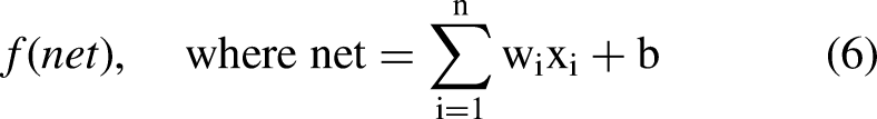
An additional operation called Rectified Linear Unit, or shortly ReLU, was added after every convolution step in the framework. ReLU, an essential unit of the CNN process, is a non-linear operation and its output is given as:

Pooling - Sub Sampling
In the next part, a pooling layer (also called sub-sampling or down-sampling) is used for the dimensionality reduction of feature maps while retaining the most useful information. This layer progressively reduces the tensor size and network computation, and therefore it can control over-fitting.
The nexus in this research is 2D max pooling in which the largest element is taken from the spatial neighborhood as:

After executing the previous steps twice (“
Fully Connected Layer- ANN Classification
Here is where the convolutional layers and a traditional Multi Layer Perceptron meet as the latter is included in the form of a “Fully Connected” layer. As the neurons from the previous layer are connected to all on the next layer, the framework at this point takes a more complex and advanced turn (see Figure 6). The basic unit in this computational model is the single-input neuron, also often called a node or unit, structure that is defined by definite functional operations of input (

Artificial Neural Network Classification Structure.
Softmax function
A softmax activation function is used in the output layer. This classifier is a generalization of the binary form of Logistic Regression and it takes a vector of arbitrary scores and normalizes it into a probability distribution.
59
In mathematical terms, the unit softmax function is defined as:

Case Study and Testing
The proposed image classification framework is applied with an up-close and detailed examination of autonomous drone landing in unknown environments. The goal is to provide a justification for the methods and to test whether the detection method is computationally efficient enough to be installed on a small embedded computer.
Image acquisition
A large set of images have been collected with SafeEYE lab during a series of test flights. In all flights, SafeEYE lab (NanoPyH5 CPU: H5, Quad-core 64-bit high-performance Cortex A53 - a low powered system) mounted on a DJI M600 drone and flown at altitudes from 30 to 150 m over a variety of terrain. During flight, images are captured every few seconds with the SafeEYE lab camera and stored in raw format. All flight followed predetermine flight paths to ensure that the same ground features would be in images at varying altitudes, and to be able to reproduce the flights, if necessary. One example of a flight path is shown in Figure 7, and a couple of examples of the view from SafeEYE lab are shown in Figure 8.
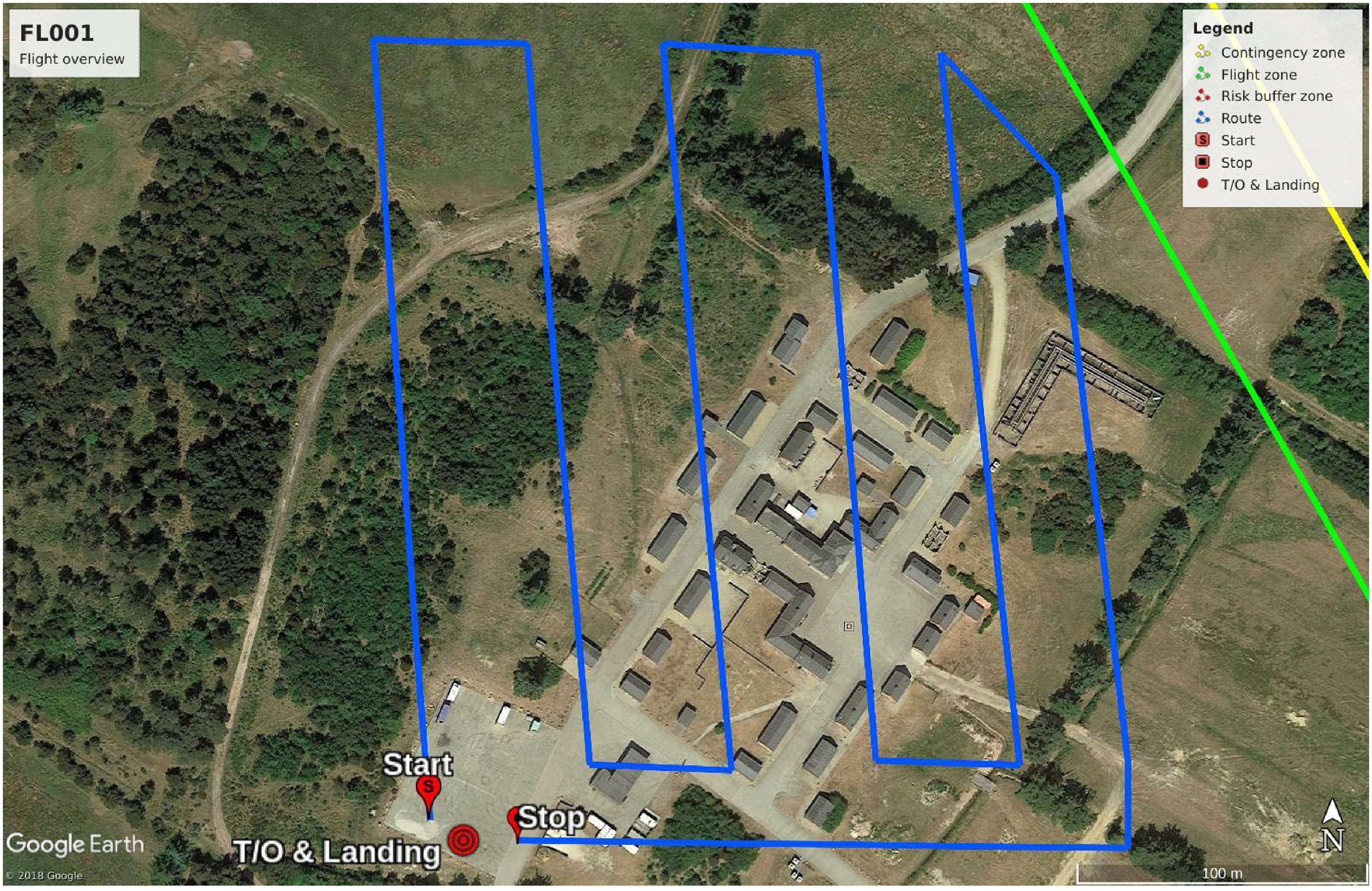
A flight plan at a military training area in Oksbøl. Some images from the flight is shown in Figure 8.

Ground images taken from the SafeEYE lab during the flight path shown in Figure 7. They are taken when the aircraft is following the right-most north-south leg.
The data collected from these campaigns provides sufficient ground images with various features from multiple attitudes and flight trajectories, vibration measures, and on-the-fly estimations.
All test flights were recorded on video and a few are made publicly available on the https://www.youtube.com/channel/UCwIUbrNZCwBuWZ4rRBUq3LAUAS-ability YouTube channel. 60 The videos starting with the date, i.e. “19.12.04”, and flight number “FL00x” refers to the flight tests as mentioned above.
Image Assessment
In Figure 8, sample images used for the classification algorithms are given. These examples are of a quality suitable for recognizing objects on ground and extracting the necessary features for image processing and classification. The imagery data set is a collection of such images taken from the camera mounted on SafeEye lab during the test flights. The raw images are then split up in smaller frames as shown in Figure 9. This is done to manually classify images according to the objects included in them and also to form an input data to the CNN structure. The frames has a resolution of 180

Frames showing examples of (columns 1-3) notlanding locations, and (columns 4-6) landing locations.
Both the output layer formation for training and the criteria for deciding whether a landing site is suitable are based on a visual inspection by a human expert. In general, the frames covered with limited color variations and green areas like grass fields are clustered as landing site whereas the ones with noise such as rocks, different colors, shadows, trees, houses, tracks etc. are categorized as not landing sites. Samples of both clusters are shown in Figure 9.
The goal of this data set is to classify areas of interest that can facilitate a landing or a crash without our human injury or fatality. The total number of images for landing evaluation is given in Tables 1 and tab:CNNLayerFormation. A common split of 75%/25% is used for partiting the data into training and test sets which are large enough to yield statistically meaningful results. Both sets are representative of data as a whole without having significantly different characteristics. The goal is to train the CNN model so that it can generalize well to new data. That is to say, the model does not over-fit the available data and it can do approximately as well on the test set as like the training set.
Input data categories

CNN Layer Formation

The overall training process of the methods provided in the previous section is summarized as follows:
The network takes training images captured by SafeEYE camera as input. The filters and feature maps are initialized and applied to these images in the first convolutional layer. The network goes through the Rectified Linear Unit with an attempt to break up the image linearity. Then, the max pooling operation down-samples each feature map by calculating the largest value in each patch, so that it can highlight the most salient features and form pooled feature maps. A second set of convolutional layer is applied to the pooled feature maps. The second set of pooled feature maps are flattened and inserted into the artificial neural network classification function. Softmax function is used as the last activation function to normalize the output.
These steps train the network with ground images. During this process, many iterations are required to update the network’s parameters such as weights and feature maps so that the algorithm can reach an optimal performance point where the classification is accurate enough. To optimize these parameters, the Adam algorithm is implemented.
61
This is a stochastic gradient-based optimization method, based on adaptive estimations of lower-order moments.
61
The method allows straightforward implementation with little memory requirement and computational efficiency, and it is compatible with the complex cases that are large with regard to data and parameters.
61
Results
The experimental findings in this section evaluate the imagery data collected for the work in the form of descriptive statistics. The section presents plots and graphs as well as the outcomes of relevant inferential statistical analyses. In the light of calculated scores and model performance, the structure is revised and altered. The results are reported in sufficient detail so that one can see what improvements were conducted and why, and to justify the proposed configurations. For processing times, the embedded computer (NanoPyH5 CPU: Allwinner H5, Quad-core 64-bit high-performance Cortex A53) could classify the flight snapshot (78 frames) into the two categories within 3 seconds.
Training CNN with the proposed settings
Results in this section demonstrates the applicability of the proposed default settings in the methodology section. Here, the study also compares the results of the initial data set with those of the further ground images. These results go beyond previous assumptions, showing that additional alterations, settings and data are necessary to provide an efficient ground image classification for autonomous landing.
The initial implementation of the model was with the image data set from the test flight at Rørdal in Aalborg, Denmark. A portion of the training data is separated into a validation data set to evaluate the model performance on this independent portion during each epoch.
The metrics of the training loss (train_loss), training accuracy (train_acc), validation loss (val_loss), and validation accuracy over time (val_loss) are used to judge the performance of the model. Accuracy calculates the percentage of the predictions that match with actual labels. The loss function is the “binary_crossentropy” which computes the cross-entropy loss between actual labels and predictions. The results of these metrics over time can be seen in Figure 10 in which the training part could fit the parameters of the model and produce improving results by iterations, but the validation part fails to provide an unbiased evaluation of a model fit while tuning parameters. Accordingly the following key findings emerge:
The model is over-fitted, due to the gap between training and validation loss. The validation part cannot provide same decreasing results after the model has “passed” the training set so the training evaluation is biased to its data. Trained network corresponds too closely to the training images and makes an overly complex explanation the idiosyncrasies in the training data. The model over-memorizes the training samples and therefore fail to fit the test data The network cannot generalize to the test samples so that it cannot involve infer and apply the training findings to test split.

Illustration of the learning curves which are calculated by the metrics of the training loss (train_loss), training accuracy (train_acc), validation loss (val_loss), and validation accuracy over time (val_loss). These results are found with the initial settings introduced in the methodology section.
Thus, over-fitting becomes a critical problem in the proposed neural network with a large number of parameters and complex co-adaptations on training data. Even though it might be acceptable to have a gap between the training loss and validation loss curves, the validation loss should not be constantly increasing as witnessed in Figure 10. Using a dropout layer is an efficient way of addressing this problem Srivastava et al. 62 . The term refers to randomly “dropping out” units, both hidden and visible ones along with their connections, from the neural network during training process.62,63 Figure 11 illustrates how the units are temporarily removed from the network, along with incoming and outgoing links.

An sample of how a thinned net production by applying dropout to a standard network
Accordingly, the proposed method can form a different architecture by randomly setting neuron input units to 0 with a frequency of rate at each step while others are scaled up by

Results of the LeNet classifier with a dropout layer.
Results from the keras classifier after the dropout layer is applied. Top text shows whether the frame can be considered, and the percentage of confidence in the classification.
As seen by these classification results, the proposed method performed well at deciding on correct landing and non-landing locations. A further point to note is that the model with the dropout layer is a rather small model and could classify these initial frames in a reasonable time which is desired for the SafeEYE lab as it will not fill up the memory on the embedded computer.
Results with Additional Data
Even though there was a significant reduction in the gap between training and validation loss due to the new dropout layer placed between the two fully connected layers at the end of the neural network, the gap between them was still present after around 200 epochs.
The results were still not desirable but hinted two things. First, the data scarcity could have been a major bottleneck for the image recognition model to reach desired classification levels after around 200 epochs. Second, the model performance relied heavily on the size of available data and SafeEYE required more test flights. After the database was updated with new images from two additional flight tests, see section , the network training was re-run with an identical setup and the results were refreshed.
The results of the later experiment found clear support for both using a dropout layer and increasing the data source. Figure 14 illustrates the performance of classification which delivered significantly better results than Figure 10 due to the proposed alterations. This yielded increasingly well assortment on both landing and non-landing fields because both training and validation loss did not deviate from each other as the previous models. The reason for this was understandably due to the diversity of data and higher variations in frames.

Refreshed learning curves of the classifier training after the data set is expanded
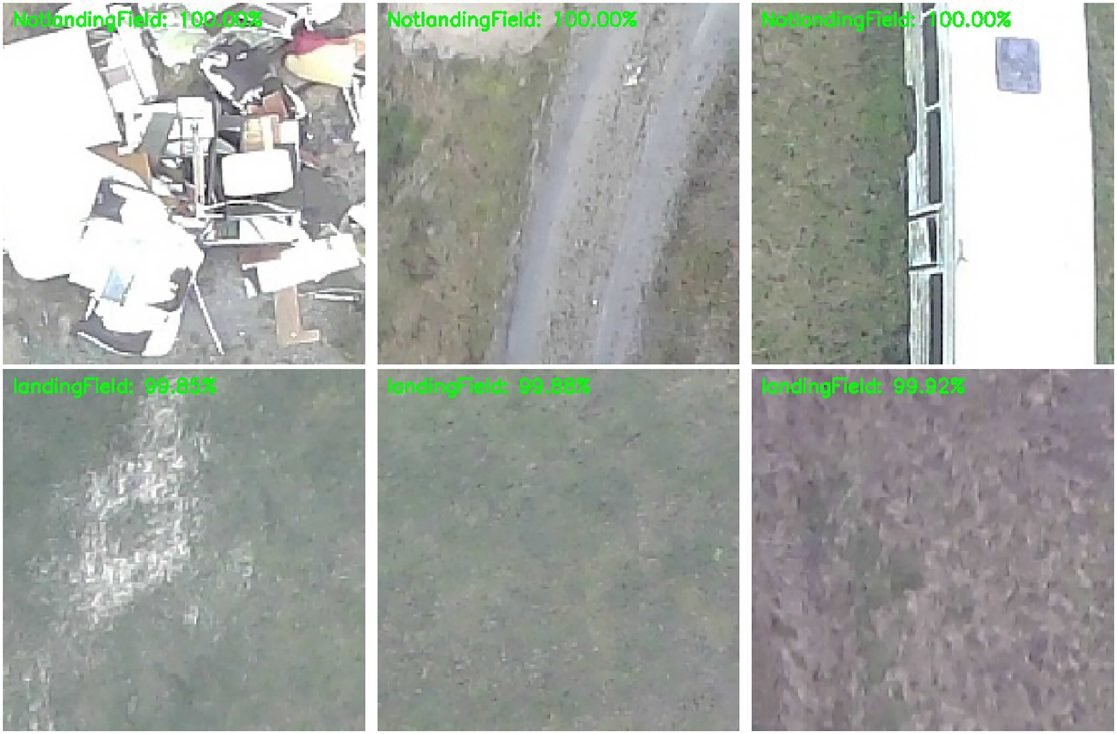
The frames in Figure 15 illustrate the overall results from the classification of frames from the military training compound. The model performs well at selecting frames where it is not suitable to land. The promising finding was that the framework could detect the noise in the frames accurately and could classify the notlandingField frames when there are any form of objects, structures, trees or natural obstacles at the image.
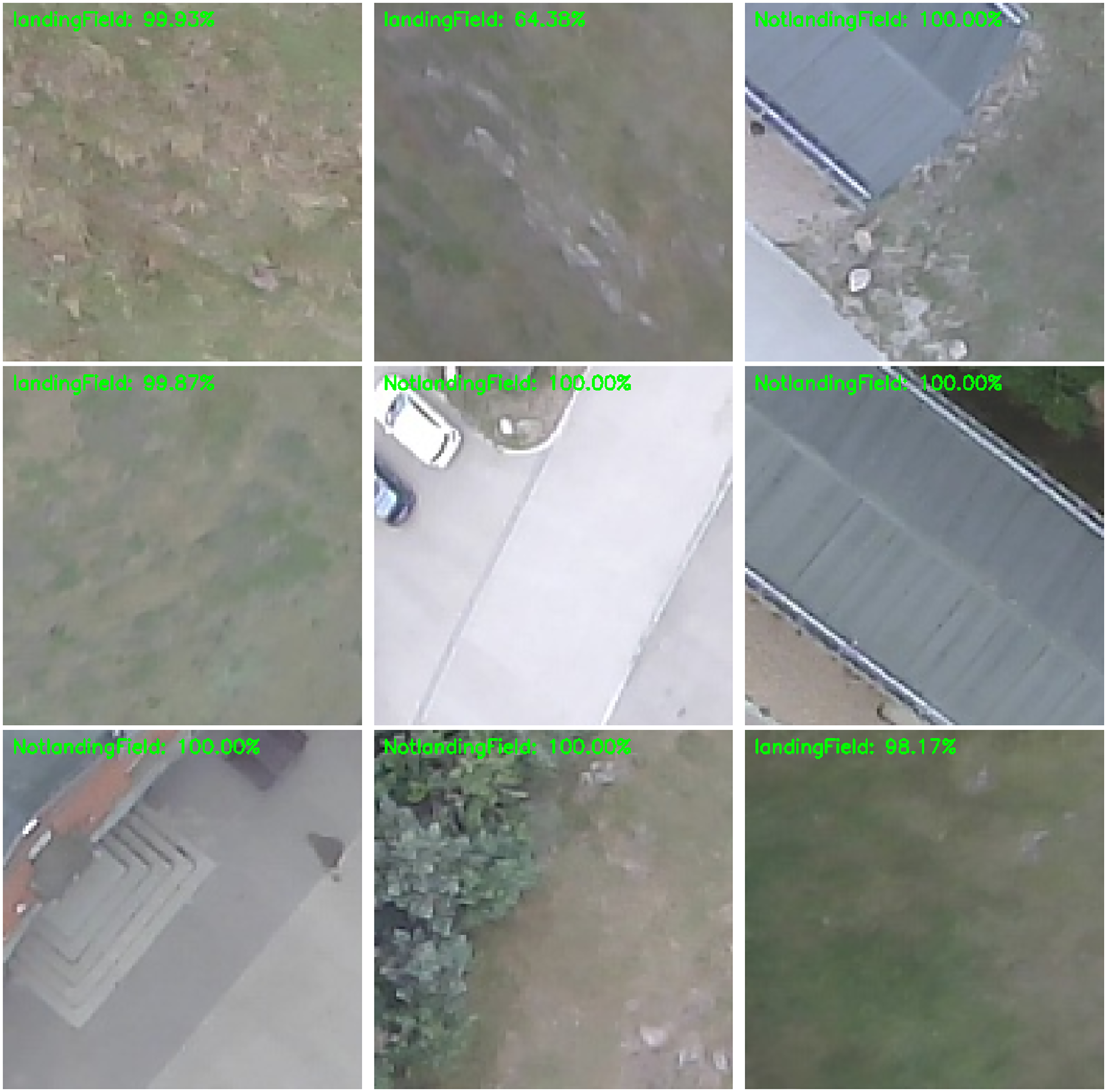
Results of the percentage of confidence in the classification from the image classifier after the model trained with the dropout layer and updated images from the new test flights.
The applicability of these new results can also be seen on the for landing locations on Figure 15. The model gave clearly well results to correctly find the grass fields as landing location, even if there were sometimes lower classification score as seen in the top middle frame. However, this could be due to the fact that the image was slightly distorted from the fish eye effect of the camera, or alternatively it was due to the slight discoloration in the ground texture.
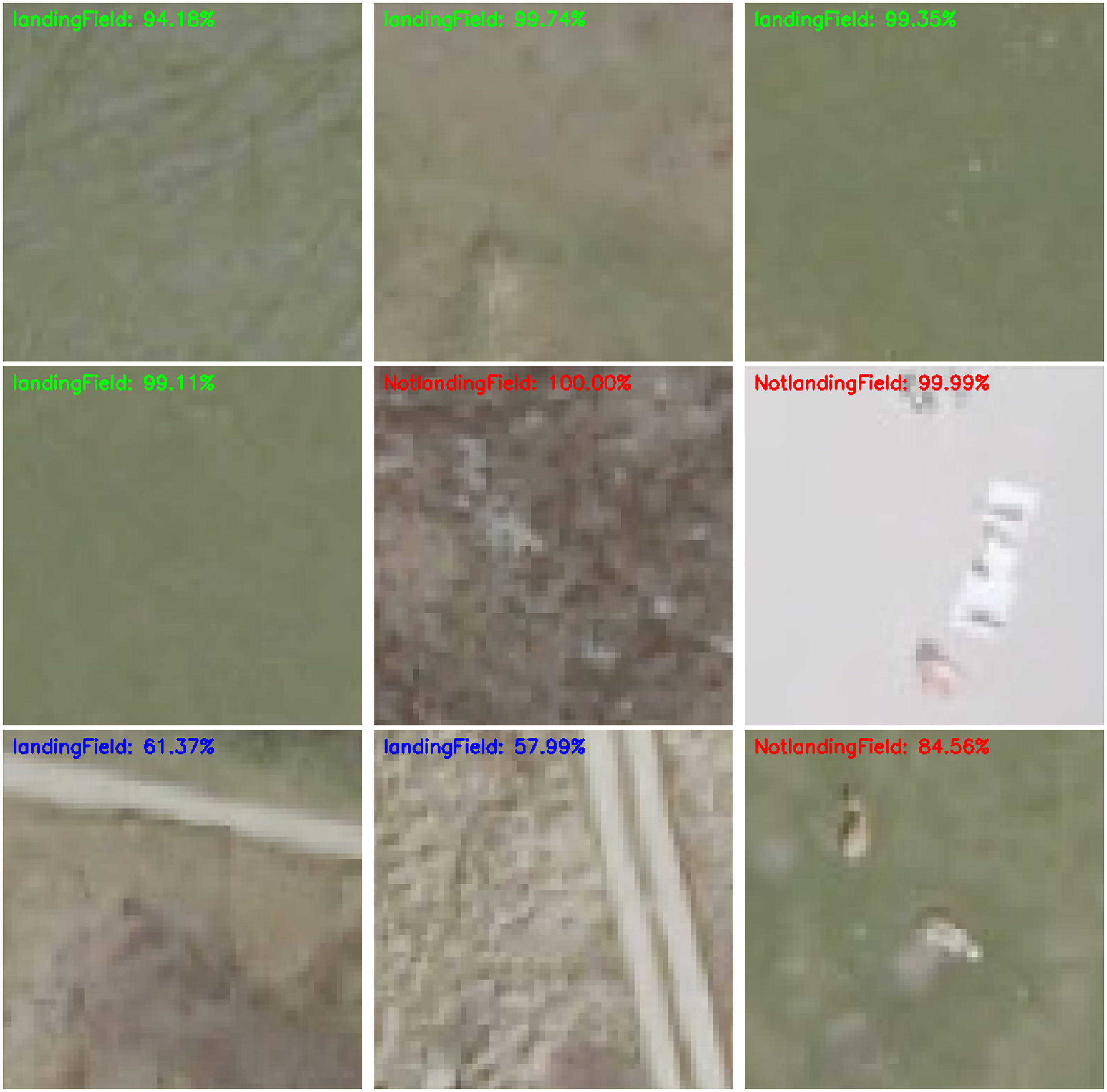
Despite the general success for the classification, inconsistent results might be obtained for certain cases. Areas with small objects or variations had edges associated with them. Safer fields, on the other hand, were free from these edges. However, some frames with indistinct edges posed some problems when carrying out the classification. To highlight these frames, the results of classification accuracy were split into three different legend colors: green for > 70% LandingField classification accuracy, blue for < 70% LandingField classification accuracy and red for NotLandingField.
As seen on Figure 16, the model was able to correctly classify the first row where the drone can land and the second row where it cannot. However, the third row is more challenging, especially for the last frame which seems a safe place to land but labelled as otherwise. This might be a minor drawback of the variance in the data present in the real world. In the convolutional layer, the model loses some information about the frame composition, and also position, and transmits incomplete knowledge further layers which might not be able to classify correctly. When the objects are under different angles, backgrounds, or lighting status, the model may not find accurate features and other information signs to classify the frame as intended. This might be the reason why the frame on the right corner of Figure 16 provided misclassification. On the other hand, the white variation could be rocks or any other obstacles in landscape level and it would be hard to say whether the model fails in classification in this example. Additionally, the convolutional networks could successfully recognize the landing images in terms of autonomous landing safety.

Further results from the classifier with a new cluster to display the classification accuracy
Summary of findings
Imagery differences can occur in different forms and be observed in interaction with various factors in different domains. To validate whether the framework could perform in such cases, an alternative data set of ground images created from orthophotos 64 is also used as a benchmark to measure how the model performs with other images collected at different settings. This can confirm the reliability of the results by a comparison between the control frames and the original SafeEYE recordings. SDFE 64 provides these open aerial photograph data which are orthorectified and geometrically corrected such that the scale is uniform. The data follow a given map projection. Like the aerial photographs taken during a drone flight, the orthophotos can be used in image analysis tasks in emergency drone landing, since they are accurate representation of unknown enviromental surfaces. The results of the model trained on the orthophotos (see Figure 17) lead to similar conclusion where there is a low training and validation loss, and a high training and validation accuracy.

Illustration of the learning curves on the orthophotos data set.
As before, it was able to correctly classify the locations as can be seen on the first and second rows of Figure 18. The frames on the bottom row, on the other hand, involve different objects that cannot be found on the drone captured data set such as unpaved road surface and small geological formations on the field. The model had the capability to rank these frames with a lower score and it proved that it does not lack the consideration of spatial relationships while processing the ground images. As the primary goal in an emergency situation is to land (or crash in the worst case) of the drone in a desired location, such ranking can be of use while selecting the best frame location.
Results of the image classifier on the orthophotos frames.
Conclusion
This work investigated the potential role of convolutional neural network based image classification for drone emergency landing. It is an original study that demonstrates the practicality of vision-based location detection on the unknown ground. CNN model allowed to encode certain image properties into the network architecture so that the forward function was more efficient to implement with reduced number of parameters. The results clearly revealed that the model was able to successfully classify landing environments and suggest relevant captions. This is in line with contemporary drone studies in the autonomous flight context postulating that artificial intelligence can perceive drone environment and take related actions for safer operations. Some limitations might be related to splitting the drone captured images into frames and applying the model to these frames. Although the classification performance was deemed acceptable, a planning through a dynamic environment might have a further positive effect on landing location classification. The confidence in the results can be strengthened with semantic-segmentation or visual scene-understanding algorithms that can operate in real-time on low-power drones. It would then be possible to make efficient use of scarce ground imagery available on embedded drone systems, compared to fully fledged workstations.
Footnotes
Acknowledgements
This work was supported by the Innovation Fund Denmark (SafeEYE Project - no. 7049-00001A).
We would like to thank Jesper Andersen (CEO & Founder at SenseAble) for his support and assistance. We would also like to extend our thanks to Simon Jensen (Assistant Engineer, Department of Electronic Systems, Aalborg University) for his help in drone operations.