The association of lift generation and evolution of wake topology behind an oscillating foil with combined heaving and pitching motion is investigated numerically at a range of bluereduced frequency (0.16 0.48), phase offset (0 315) and Reynolds number (1000 4000). The pitch-dominated kinematics that coincide with the range of 120 and 225 suggests that leading edge vortices are suppressed while trailing edge vortices dominate the wake with increasing reduced frequency. This corresponds to a transition in wake topology from a to a reverse Von Kármán wake mode. Contrarily, heave dominated kinematics (120 225) did not exhibit any wake topology transition with increasing . The temporal lift variation associated with heave-dominated regime further revealed a symmetric feature in terms of the time taken to attain peak lift generation within an oscillation cycle. This temporal symmetry was, however, lost as kinematics transitioned from heave- to pitch-dominated regime. Analyzing the wake evolution and lift features at quarter phase of an oscillation cycle revealed the existence of a correspondence between the two processes during the heave- and pitch-dominated kinematics.
The fundamental mechanisms of aerodynamic and hydrodynamic force generation behind oscillating foils have been under prominent investigation in the past few decades.4,1,3,5,2 The flapping motion of airfoils provides an effective model to understand insect and bird flights,5 while rigid body oscillatory kinematics of hydrofoils in purely pitching or plunging motion closely mimic the biological kinematics within the realm of fish swimming.2 Studies relevant to fluid-structure interaction, which encompass the complex oscillatory dynamics of rigid and flexible bodies11,89,10,7,6 have also observed close association of vortex synchronization and propulsive performance. For example, reverse Von Kármán (rBvK) wake topology had been observed to coincide with a thrust generating propulsive performance.4,9 Similarly, 2P wake mode had been observed in wakes of fish that coincided with an optimum propulsive swimming efficiency.1213,9 Asymmetric wake topologies have also been observed to generate high lift7 which present applications in maneuvering of aerial robotic wings and underwater propulsors.2 Transition of wake topology and its coincidence with changes in propulsive performance has further garnered attention from the research community. Godoy-Diana et al.9 reported that drag-to-thrust transition in case of purely pitching foil occurred ahead of a wake transition from Benard Von Kármán (BvK) to rBvK topology. Such transitions in performance and wake modes were represented on a phase map characterized by increasing Strouhal number () and amplitude (), where is the frequency of oscillations and is freestream velocity. Schnipper et al.10 also reported apparent transitions in wake topology on a similar phase space, as previously presented by9. Their study provided additional insights into the mechanism that contributed to the wake transition from to rBvK.10 While these studies focused heavily on aspects of thrust generation for an optimal swimming performance, limited work has been conducted in terms of coinciding lift generation. We believe that the evaluation of performance features in terms of lift, and its corresponding association with the wake modes, could enhance development of conceptual designs of propulsors. This includes improving their maneuverability in conditions of collision and enemy avoidance for both aerial and underwater applications.
Previous studies7 highlighted aspects of lift generation, and their association with wake modes, mostly in cases of oscillating foils with a single degree of freedom motion (such as plunging). The growth of leading edge vortex (LEV) and its dynamic interactions with trailing edge vorticity was found to hold some uniqueness compared to a purely pitching motion, that was dominated by trailing edge vortex (TEV) shedding.14,1 Foils with coupled heaving and pitching kinematics have also been investigated in great detail recently,15 although the performance features were primarily evaluated in terms of propulsive thrust generation and efficiency. Moreover,16 extensively evaluated the wake evolution and apparent association of wake features with performance, including temporal lift variation within a single shedding cycle. However, the kinematic settings were limited to cases with peak performance such as large thrust production and peak propulsive efficiency. Here, we expand our study to an extended parameter space for coupled motion kinematics, while focusing on correspondence of the wake topology and characteristic lift generation.
The main objective of this numerical study is to investigate and report on novel findings concerning wake modes that dominate the transitioning (from a heave- to pitch-dominant motion setting) kinematics of an oscillating foil. We provide additional insights into the coinciding differences in lift characteristics. blueThe changes in kinematics at 1000 4000 are governed primarily by varying the phase offset () between the heaving and pitching motion (0 315), reduced frequency () of oscillation in the range of 0.16 0.48 and Strouhal number based on trailing edge amplitude () which varies in range of 0.060.34. Here, we restrict our wake and performance evaluation to 1000, at which case the flow exhibits all necessary coherence features without three-dimensional turbulent flow complexities of higher Reynolds numbers. This is followed by investigating the association of wake features with temporal lift variations for specific cases of and to reveal correspondence between kinematics, performance and wake mode formations.
Methodology
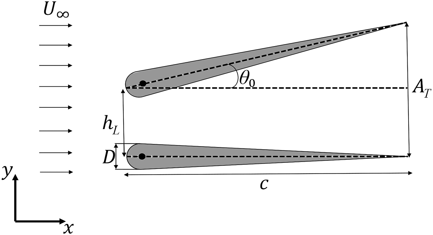
Flow around a teardrop foil is numerically examined at a range of reduced frequency (0.16 0.48), phase offset (), and Reynolds number (1000 4000). The maximum thickness () to chord length () ratio of the foil is . The foil oscillates with a combined heaving and pitching motion at a point located approximately 0.05 from the leading edge. Figure 1 depicts the two-dimensional representation of the oscillating foil where heave and pitch amplitude are denoted by and , respectively. The resultant trailing edge amplitude is depicted as . For this study, and are fixed at 0.25 and 10, respectively. The sinusoidal motion profiles of heave () and pitch (), where pitching has a phase advancement of relative to heaving, are represented using:
Schematics of the foil kinematics.
The phase offset variation directly resulted in a variation of trailing edge amplitude (). Van Buren et al.15 highlighted that changes in dictated the motion setting in terms of pitch- or heave-dominated kinematics. Thus, it could pose apparent effects on the propulsive performance. Despite the aforementioned efforts, there has not been any attempts to characterize the coinciding lift generation and wake topology in the heave-dominated (i.e. 180) and pitch-dominated (i.e. 0 and 225) regimes. blueThe specified range of for heave and pitch-dominated kinematics were obtained based on the ratio of peak leading edge to trailing edge amplitude of foil, i.e. (see Figure 1), within half oscillation cycle. If the ratio was greater than 1, the corresponding value would fall under regime of heave-dominated kinematics. In contrast, if the ratio was observed to be lesser than 1, the coinciding would indicate a pitch dominated motion. It is also important to note that the most propulsively efficient phase offset of 90,1 employed for various studies,18,17 is equivalent to based on the reference coordinate system employed by15. This study follows a similar coordinate system as.15
On account of variation in and , the Strouhal number () also varied in the range of 0.06 0.34, where the maximum and minimum correspond to 0 and 180, respectively. Andersen et al.19 have indicated that interesting and significant transitions in the wake of flapping foils were observable within a Strouhal number range of 0.2 0.4. This also coincides with the range for optimal propulsive efficiency in swimming mammals, and flights of birds and insects, respectively.4,2,20 blueFurther, the specified range of had been observed to preserve the wake two-dimensionality of a flapping foil that involved either a pure pitching, or a coupled motion setting.21 This further justified the parameter space considered in the current study. blueThe detailed analyses of the coinciding wake and performance characteristics with the heave- and pitch-dominated kinematics is further limited to a chord-based Reynolds number of , where transition of wake modes are more clearly evident.22,23 This choice of also followed closely with assessments of.9,10,24,17 These studies described transitions in the wake of purely pitching foils and provided a insight into the quasi-two-dimensional and three-dimensional characteristics of wake structures.24
Numerical Details
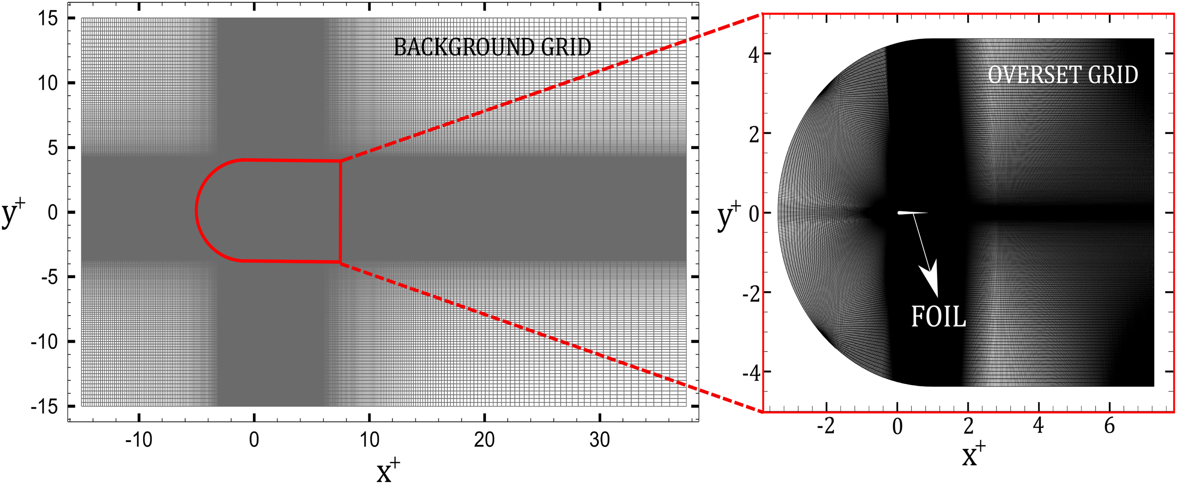
The continuity and Navier-Stokes equations were solved directly using OpenFOAM, which is a finite-volume method that has been extensively used for simulating wake dynamics of oscillating foils and panels.27,26,18,25,2816 The prescribed kinematics of oscillating foil was modelled using Overset Grid Assembly (OGA) method,29 based on a stationary background grid and a moving overset grid. Extensive details of the method can be found in.16Figure 2 depicts the computational domain that highlights the C-type overset boundary containing the foil. Boundary condition at the inlet was prescribed as uniform fixed velocity (Dirichlet) and a zero normal gradient (Neumann) for pressure. At the outlet, a zero-gradient outflow boundary condition was implied.24 The top and bottom walls are further prescribed a slip boundary condition that effectively models the open surface flows and closely resembled experimental conditions.15,26 At the foil boundary, we assigned the no-slip velocity and zero-gradient pressure conditions. Figure 3 further depicts the non-homogeneous hexahedral grid that is used for this study, which comprise of a C-type grid (for the foil geometry and motion), which overlaps with a rectangular background grid. Higher refinement was provided in critical overlapping regions, such that the near body vortex shedding and wake interactions were accurately captured. The grid further expanded towards the domain boundaries at an expansion factor of less than 1.02. The flow was solved using overPimpleDyMFoam solver, which integrated the functionality of OGA and the PIMPLE algorithm. Second order accurate backward and central difference schemes were employed for temporal and spatial discretizations, respectively.27 The momentum equations were specifically solved using Preconditioned Biconjugate Gradient (PbiCGSTAB) method, whereas Preconditioned Conjugate Gradient (PCG) method was employed for pressure poisson equation.24,18
Schematics of the computational domain (not to scale) with boundary conditions.
Schematics of the grid and Overset Grid Assembly method.
A spatial convergence analysis was also completed at 8000, 0.25, 15, 270 and 0.67. This enabled a comparative evaluation with experiments of.15Table 1 and Figure 4 summarize the grid convergence results involving three grids, wherein the ratio () of minimum grid size element () to Kolmogorov scale () was kept below 10 within the critical region near the foil, following the recommendations of30 (see Table 1). Here, Kolmogorov scale was calculated based on kinematic viscosity () and the dissipation rate of turbulence kinetic energy (), given by the relation .31 The coefficient of thrust (), which was averaged over the final 10 oscillating cycles following the statistical convergence, was used as a quantitative estimate for spatial grid convergence. The relative error () calculated with respect to the experimental results of15 was below 5 for Grid2. Figures 4(a) and 4(b) shows the instantaneous variation, and cross-stream distribution of mean streamwise velocity () at increasing streamwise distance , for the three grids discussed in Table 1. These results clearly show that propulsive performance and wake characteristics of the foil are not sensitive to spatial grid resolution. This further provided sufficient confidence to use Grid 2 for our analysis. The time-step size () was also set, such that the ratio of eddy turnover time () to for the smallest dissipative eddy31 yields at least 100 time-steps. This ensured that our simulations had adequate resolution to capture essential turbulent characteristics, which aligned with the recommendations followed in the numerical study of wake turbulence by.32 The Courant number () was also maintained below 0.5, similar to the simulations of.26 Validation of the numerical solver with experiments15 is also depicted in Figure 4(c-d). Specifically, Figure 4(c) shows that the computationally predicted for 00.25, 15, 270 and 0.67, was in good agreement with experiments.15Figure 4(d) further depicts the instantaneous contribution of the transverse force () and pitch moment () to the total power () within one oscillation cycle. The computational prediction closely follow the quantified variation observed from experiments.15 Extensive efforts for verification and validation of the numerical solver with respect to domain size, spatial and temporal grid, OGA solver and boundary conditions can be further found in.26,33,16
Grid sensitivity and validation study. (a) and (b) represent the unsteady variation of , and cross-stream () wake profiles at increasing streamwise distance (), respectively, for the three grids under investigation. Comparison of (c) numerically obtained variation of and (d) unsteady contributions of transverse force and pitch moment to the total input power of the oscillating foil with experiments of.15
Grid convergence analysis for oscillating foil. Here, represents the sum of hexahedral elements in background and overset grids.
We begin by evaluating the wake modes and their coincidence with performance features for oscillating foils, in terms of lift generation, within the heave- and pitch-dominated ranges of phase offset (). blueThe observations correspond to a fixed 1000. This includes assessments at increasing reduced frequencies (), where substantial increment in vorticity generation and circulation could contribute towards changes in temporal lift features within an oscillation cycle.7 The instantaneous vortex shedding events within an oscillation cycle for heave- and pitch-dominated regimes of coupled kinematics are considered to reveal apparent association of lift variation with unique wake modes observed at increasing and .
Lift Generation and Wake Topology
Lift variations are examined in terms of root-mean-square of lift coefficient () in Figure 5(a) at increasing and . Here, was evaluated using the expression:
where, is the cross-stream force generated by the oscillating foil, denotes the dynamics pressure and represents the span. Pitch-dominated regime of coupled kinematics coincides with 180 and 225, while heave-dominated regime is governed by 180 225. Figure 5(a) shows a decreasing magnitude of as transitions from a pitch- to heave-dominated regime. This trend remains consistent at increasing , although the effect appears relatively stronger at higher , where the rate of reduction in with increasing is large compared to observations at 0.32. We further observe that as increases above 225, depicts an increasing trend that coincides with a reverse transition towards pitch-dominated kinematics regime. Thus, it is evident that heave-dominated regime coincides with low magnitudes of , contrary to the features observed in pitch-dominated regime. It will be interesting to evaluate the coinciding changes in wake formation within the heave- and pitch-dominated regimes. This will also help in investigating apparent association of wake topology and lift characteristics.
(a) Variation of with increasing and , and (b) Wake mode transition depicted on a phase space.
The wake modes at increasing and are depicted on a phase-map shown in Figure 5(b). For the pitch-dominated regime in the range of , it is evident that the wake associated with is wholly dominated by a wake mode. This topology is characterized by shedding of two vortex pairs, which comprises of counter-rotating leading and trailing edge vortex structures.10,16 Increasing to 0.48 shows a transition to vortex modes, including rBvK and BvK, in which only trailing edge structures dominate the vortex shedding and corresponding wake formation.14,10As the kinematics switch to heave-dominated regime, governed by 180 and 225, we observe that wake configuration is retained at the highest of 0.48. This is in contrast to the observations made in pitch-dominated regime discussed earlier. The lack of a wake transition from to with increasing is attributed to the decreasing trailing edge vorticity relative to the vorticity generated at the leading edge with increasing to 225. This further coincides with a decrease in trailing edge amplitude as described by.15,22 We also observe that the range of between 0.24 and 0.40 shows a delayed wake transition from to within heave-dominated regime compared to the pitch-dominated regime at , for example. This could again be an implication of weak or no interaction (and merging) near the trailing edge of the foil due to lower strength of generated vorticity. blueThe mode observed at lower , which coincides with both 225 and 270, depicts the wavy Von Kármán mode observed in some studies conducted previously.34,23 Lentink et al.34 and23 observed no noticeable shedding of near wake vortex structures for the mode. The separated shear layer remains undisturbed until an initial instability starts to develop at some distance downstream of the trailing edge.34 The pitch-dominated regime above 225 depicts a similar wake topology and transition as observed for 180.
In order to further evaluate temporal lift features that are pertinent to heave- and pitch-dominated motion kinematics, it is important to consider the variation of instantaneous lift () within one single oscillation cycle.
Vortex Shedding and Lift Variation
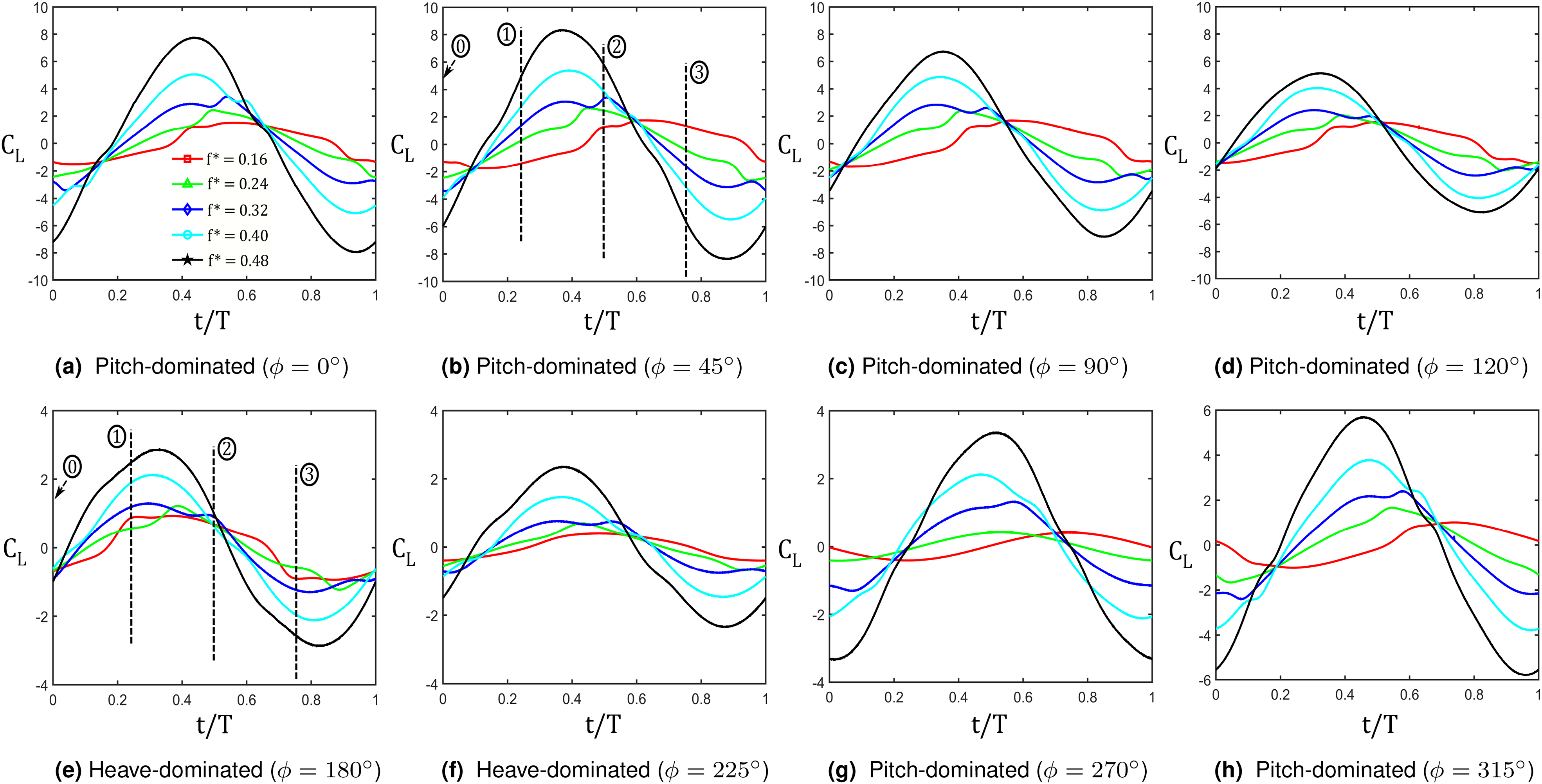
Figure 6 depict the variation of within one oscillation cycle. The apparent effect on lift features and its association with transition of pitch- to heave-dominated regimes of coupled kinematics are more evident here. At 0.16, the temporal variation in shows a low amplitude within the entire range of considered in this study. This also supports the observation from Figure 5(a) where low was evident at 0.16 and increasing from 0 to 315. The amplitude of starts to increase as increases above 0.16. While the effects on temporal variation with respect to the shedding period are not clearly identifiable at low , we observe substantial changes at above 0.32. The similarities and association of lift features with pitch- or heave-dominated regimes are also more evident at higher .
Temporal variation of at increasing and (a) 0, (b) 45, (c) 90, (d) 120, (e) 180, (f) 225, (g) 270, (h) 315.
With increasing from 0 to 120 in Figure 6, we observe that variation become more symmetric about the half shedding period () and , in comparison to the trends observed at 0 and 45. This symmetric feature in appears more prominent within the heave-dominated range of . blueThis characteristic lift variation could also offer capabilities in terms of achieving low amplitude maneuvers in shorter time-period for robotic flights and swimmers which can detect and avoid collisions with obstacles on course. A higher requirement, however, will still be required in order to achieve such lift signature within the heave dominated kinematic regime. Ahead of 225, we see that this symmetric temporal characteristic is lost, similar to the observations for 90. A longer proportion of the shedding period is characterized by a rise in towards its local maximum, and followed by its steady decrease as the shedding cycle ends. blueContrary to the application posed by lift features of heave dominated kinematics, it appears that pitch-dominated regime offers a high magnitude lift generation capability rather than a short-time directional maneuver. In situations like surface lift-off during strong wind gusts or sudden need of greater side force generation during cyclonic hurricane avoidance in marine robots, such high magnitude lift generation will therefore present greater applications. The wake phase map (Figure 5(b)) further showed that heave-dominated regime is largely characterized by a paired wake () formation at increasing , while pitch-dominated regimes showed an eventual wake transition to . Thus in the latter case, only two single counter-rotating vortex structures shed from the trailing edge that dominate the wake. It is important to investigate if any close association exists between temporal lift features and wake formations within the heave- and pitch-dominated regimes.
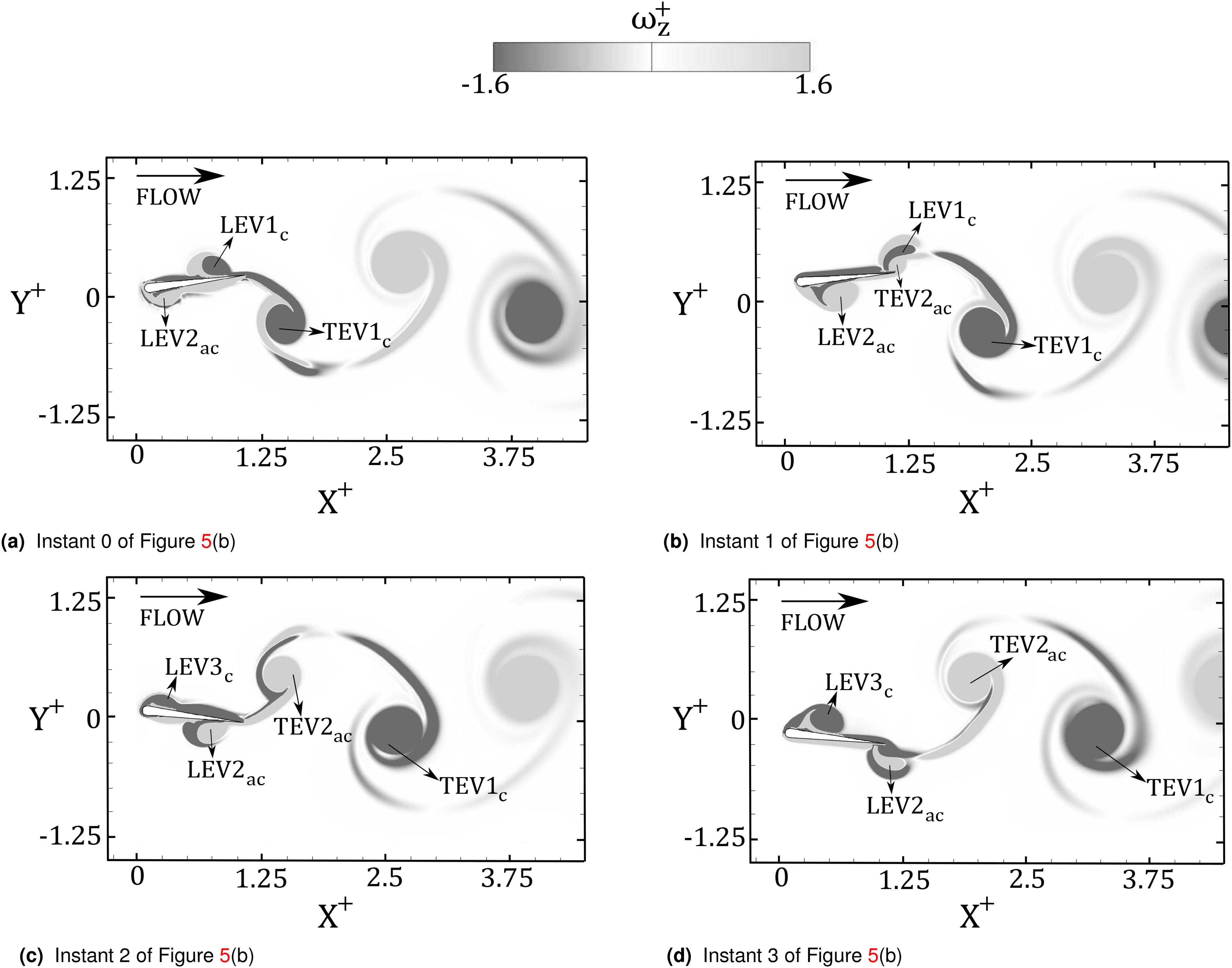
We proceed by evaluating the instantaneous spanwise vorticity distribution around the foil and in the near wake at each quarter phase () of the oscillation cycle. For brevity, only two specific cases are examined at the highest within this parameter space (i.e. 0.48), while each case represents either a pitch- or heave-dominated regime. Figures 7 and 8 depict the spanwise vorticity () distribution at each quarter period of an oscillation cycle, for 45 and 180, respectively. As described before, the former represents a case of pitch-dominated regime while the latter corresponds to a heave-dominated kinematics. At 45 in Figure 7, it is evident that the near wake formation is dominated by trailing edge structures () that appear to possess a relatively larger circulation strength compared to the leading edge structure () before shedding in the wake. This is despite the fact that leading edge structures () are formed and move downstream within each half shedding cycle.
Snapshots of normalized spanwise vorticity () depicting wake formation at 0.48 and 45, at quarter period of oscillation cycle: (a) , (b) , (c) and (d) . blue and depict normalized streamwise and cross-stream distance, respectively.
Snapshots of normalized spanwise vorticity () depicting wake formation at 0.48 and 180, at quarter period of oscillation cycle, i.e. (a) , (b) , (c) and (d) . blue and depict normalized streamwise and cross-stream distance, respectively.
The formation process of the rBvK wake at is quite similar to those described for purely pitching foils.14,10Figure 7(a) shows a strong clockwise trailing edge structure () which is almost on the verge of separation from the foil trailing edge. We further observe a weak vortical structure originated at the leading edge (), which appears to interact with the attached leg of . At 0.25 in Figure 7(b), appears stretched on account of the formation of . As grows in circulation strength and size at 0.5 in Figure 7(c), LEV2 near the trailing edge undergoes stretching as another anti-clockwise TEV starts to develop. This is evident at 0.75 in Figure 7(d), which is consistent with the observations at 0.25 in Figure 7(b). further grows and reach approximately the mid-chord region of the foil. Overall, the wake is dominated by trailing edge vorticity, while leading edge vorticity disintegrate and diffuse without contributing to the wake formation. Counter-rotating TEV structures grow and shed in the wake during the majority of shedding period, which coincides with lift characteristics depicted in Figure 6(b). This shows a more prolonged fluctuation towards extremas within an oscillation period. This rise and fall corresponds to the development and shedding of anti-clockwise and clockwise structures, respectively, shown in Figure 7(b,d). Instants 0, 1, 2 and 3 that are marked in Figure 6(b) correspond to each quarter phases of oscillation period in Figures 7(a), 7(b), 7(c) and 7(d), respectively. It is evident that ahead of instant 1, an extrema of is reached in Figure 6(b), which coincides with shedding of in Figure 7(b). Similarly, we observe reaching another extrema ahead of instant 3 in Figure 6(b) with a negative sign, which coincides with the shedding of an anti-clockwise structure, . Similar shedding events are also observed for other cases of , which depict pitch-dominated regime. However, they are not depicted or discussed here for brevity since they follow a very similar wake formation mechanism as that of 45 in Figure 7.
The wake formation at 180, which corresponds to a particular case of heave-dominated regime, is shown in Figure 8. Similar to the case for pitch-dominated regime, each of the four snapshots in Figure 8 corresponds to Instants 0, 1, 2, and 3 in Figure 6(e), respectively. At 0, vortex has shed into the wake, which appears to start forming a pair with . Moreover, appears stretched on account of straining induced by . It is also apparent that and grow in size on the pressure and suction side of the oscillating foil. As the foil reach 0.25 in Figure 8(b), is detached and advects as a counter-rotating pair of . The induced straining by , which is just beginning to form, appears to distort in Figure 8(b) and 8(c). At 0.5, pairs with the strained near the foil trailing edge, which by 0.75 sheds from the foil trailing edge and advects into the wake (see Figure 8(d)). This is consistent with the observations made during the first half shedding cycle in Figure 8(b). By relating the advection of leading edge structures with lift characteristics for 180 in Figure 6(e), it becomes evident that symmetric variations that are attained with respect to the half shedding period are clearly associated with advected LEV structures for heave-dominated kinematics presented here. Ahead of instant 1 marked in Figure 6(e), we observe that grows in strength and size, for example at 0 in Figure 8(a), while increases towards a local extrema. However ahead of instant 2, decreases towards larger negative values. This coincides with advection of in the wake, shown in Figure 8(b), and early growth of near the foil trailing edge. At instant 3, which lies just before reaching a local negative extrema in Figure 6(e), we notice that is enlarged while has almost reached the trailing edge in Figure 8(c). As and shed, the corresponding growth and advection of a new trailing edge structure and again corresponds to an increasing towards positive values as the shedding cycle ends. It is thus apparent that for heave-dominated kinematics, the growth and coherence of advecting LEV structures reveal a more symmetric attainment of extremas in an oscillation cycle. Contrarily, previously discussed pitch-dominated kinematics confirm that eventually disintegrates near the foil trailing edge, which therefore corresponds to a lack of symmetry in development of peaks in the profile of at around half the shedding period.
Conclusions
The wake topology transition, and its correspondence with lift features, are numerically examined for an oscillating foil in coupled heaving and pitching motion with heave and pitch amplitudes corresponding to 0.25 and 10, respectively. The variation in phase offset () between the motions contribute to the changes in trailing edge amplitude, thereby promoting the transition of kinematics between pitch-dominated (0 180, 225 360) to heave-dominated (180 225) motion regimes.
Assessment of lift variations, in terms of root-mean-square (), reveal low magnitudes within the heave-dominated regime. The magnitude of increases as kinematics switched to a pitch-dominated regime. The phase map depicting the wake mode transition also reveal that heave-dominated regime does not exhibit wake transition from to with increasing . This is contrary to the wake features observed for the pitch-dominated kinematics. The reduction of trailing edge amplitude within the heave-dominated regime corresponds to decreasing relative vorticity generated at the trailing edge compared to the leading edge.22 This characteristic feature thus yields a paired configuration of leading and trailing edge vortical structures, even at high for the heave-dominated kinematics, thereby explaining the mode configuration.
The temporal assessments on lift variation within an oscillation cycle provided additional insights into association of lift characteristics and wake mode transitions identified for the heave- and pitch-dominated regimes. It was evident that heave-dominated regime is characterized by an apparent symmetry in variations of , such that there is a mirror image of the extrema about the half shedding period. The growth and advection of structures followed by their pairing with structures, which yields a wake, coincides with unique temporal lift features during the heave-dominated kinematics. The pitch-dominated regimes, however, depicted a lack of symmetry in temporal lift variation, while a major portion of the shedding period is spent in attaining a single extrema. The disintegration of , and its lack of contribution towards wake formation, coincides with a change in lift behaviour within an oscillation period. The transition in wake topology and the associated lift characteristics thus indicate that the heave-dominated kinematics of coupled motion can offer a more rapid maneuvering control, although the magnitude of lift generation is low. The pitch-dominated cases, however, could yield larger lift, while a rapid maneuvering is not feasible in such a coupled motion regime.
Footnotes
ORCID iDs
Suyash Verma
Muhammad S.U. Khalid
Acknowledgements
This research has received support from the Canada First Research Excellence Grant. The computational analysis was completed using Compute Canada clusters.
References
1.
AndersonJMStreitlienKBarrettDSet al. Oscillating foils of high propulsive efficiency. J Fluid Mech1998; 360: 41–72. DOI: 10.1017/S0022112097008392.
2.
SmitsAJ. Undulatory and oscillatory swimming. J of Fluid Mechanics2019; 874. DOI: 10.1017/jfm.2019.284.
3.
SunMTangJ. Unsteady aerodynamic force generation by a model fruit fly wing in flapping motion. J Exp Biol2002; 205: 55–70. DOI: 10.1242/JEB.205.1.55.
4.
TriantafyllouGSTriantafyllouMSGrosenbaughMA. Optimal thrust development in oscillating foils with application to fish propulsion. J Fluids Struct1993; 7(2): 205–224. DOI: 10.1006/jfls.1993.1012.
CalderonDECleaverDJGursulIet al. On the absence of asymmetric wakes for periodically plunging finite wings. Phys Fluids2014; 26(7): 349–376. DOI: 10.1063/1.4891256.
7.
CleaverDJWangZGursulI. Bifurcating flows of plunging aerofoils at high Strouhal numbers. J Fluid Mech2012; 708: 349–376. DOI: 10.1017/jfm.2012.314.
Godoy-DianaRAiderJLWesfreidJE. Transitions in the wake of a flapping foil. Physical Review E2008; 77(1): 016308.
10.
SchnipperTAndersenABohrT. Vortex wakes of a flapping foil. J Fluid Mech2009; 633: 411–423. DOI: 10.1017/S0022112009007964.
11.
WilliamsonCHRoshkoA. Vortex formation in the wake of an oscillating cylinder. J Fluids Struct1988; 2(4): 355–381. DOI: 10.1016/S0889-9746(88)90058-8.
12.
MüllerUKSmitJStamhuisEJet al. How the body contributes to the wake in undulatory fish swimming. J Exp Biol2001; 204: 2751–2762. DOI: 10.1242/jeb.204.16.2751.
13.
MüllerUKVan Den BoogaartJGVan LeeuwenJL. Flow patterns of larval fish: Undulatory swimming in the intermediate flow regime. J Exp Biol2008; 211: 196–205. DOI: 10.1242/jeb.005629.
14.
KoochesfahaniMM. Vortical patterns in the wake of an oscillating airfoil. AIAA J1989; 27(9): 1200–1205. DOI: 10.2514/3.10246.
15.
Van BurenTFloryanDSmitsAJ. Scaling and performance of simultaneously heaving and pitching foils. AIAA J2019; 57(9): 3666–3677. DOI: 10.2514/1.J056635.
16.
VermaSHemmatiA. Evolution of wake structures behind oscillating hydrofoils with combined heaving and pitching motion. J of Fluid Mechanics2021; 927. DOI: 10.1017/jfm.2021.750.
17.
LagopoulosNSWeymouthGDGanapathisubramaniB. Universal scaling law for drag-to-thrust wake transition in flapping foils. J Fluid Mech2019; 872: R1. DOI: 10.1017/jfm.2019.361.
AndersenABohrTSchnipperTet al. Wake structure and thrust generation of a flapping foil in two-dimensional flow. J Fluid Mech2017; 812: R4. DOI: 10.1017/JFM.2016.808.
20.
WuXZhangXTianXet al. A review on fluid dynamics of flapping foils. Ocean Eng2020; 195: 106712. DOI: 10.1016/J.OCEANENG.2019.106712.
21.
Zurman-NasutionANGanapathisubramaniBWeymouthGD. Influence of three-dimensionality on propulsive flapping. J Fluid Mech2020; 886. DOI: 10.1017/JFM.2019.1078.
22.
VermaSHemmatiA. Characterization of bifurcated dual vortex streets in the wake of an oscillating foil. J Fluid Mech2021. (under–review).
23.
VermaSHemmatiA. Route to transition in propulsive performance of oscillating foil. Physical Review E2021. (under–review).
24.
DengJSunLShaoX. Dynamical features of the wake behind a pitching foil. Physical Review E 2015; 92(6): 063013. DOI: 10.1103/PhysRevE.92.063013.
25.
BoseCGuptaSSarkarS. Dynamic interlinking between near-and far-field wakes behind a pitching-heaving airfoil. J Fluid Mech2021; 911. DOI: 10.1017/jfm.2020.1030.
26.
HemmatiAVan BurenTSmitsAJ. Effects of trailing edge shape on vortex formation by pitching panels of small aspect ratio. Physical Review Fluids2019; 4(3): 033101. DOI: 10.1103/PhysRevFluids.4.033101.
27.
SenturkUSmitsAJ. Numerical simulations of the flow around a square pitching panel. J Fluids Struct2018; 76: 454–468. DOI: 10.1016/j.jfluidstructs.2017.11.001.
MerrillBEPeetYT. Effect of impinging wake turbulence on the dynamic stall of a pitching airfoil. AIAA J2017; 55(12): 4094–4112. DOI: 10.2514/1.J055405.
33.
VermaSHemmatiA. Performance of overset mesh in modeling the wake of sharp-edge bodies. Computations2020; 8(3): 66. DOI: 10.3390/computation8030066.
34.
LentinkDMuijresFTDonker-DuyvisFJet al. Vortex-wake interactions of a flapping foil that models animal swimming and flight. J Exp Biol2008; 211(2): 267–273. DOI: 10.1242/jeb.006155.