
Abstract
Hybrid UAVs have gained a lot of interest for their combined vertical take-off & landing (VTOL) and efficient forward flight capabilities. But their control is facing challenges in over-actuation and conflicting requirements depending on the flight phase which can easily lead to actuator saturation. Incremental Non-linear Control Allocation (INCA) has been proposed to solve the platform’s control allocation problem in the case of saturation or over-actuation by minimizing a set of objective functions. This work demonstrates INCA on quadplanes, an in-plane combination between a quadrotor and a conventional fixed-wing, and proposes an extension to control the outer loop. The novel controller is called Extended INCA (XINCA) and adds the wing orientation as a force-generating actuator in the outerloop control optimization. This leads to a single controller for all flight phases that avoids placing the wing at negative angles of attack and minimizes the load on hover motors. XINCA has low dependence on accurate vehicle models and requires only several optimization parameters. Flight simulations and experimental flights are performed to demonstrate the performance.
Introduction
Unmanned Aerial Vehicles or UAVs have gained a tremendous amount of popularity. Not only have they proven to be valuable research platforms and entertaining toys, but they have also found many other applications in fields like defense, 1 surveillance, 2 medical assistance,3,4 transportation of both goods and humans, 5 agriculture, 6 inspection, 7 mapping, 8 and many others.
Some challenges that are often faced in UAV design are endurance, reliability, versatility, and affordability. Existing solutions often perform well on some but not all of these aspects. Fixed-wing aircraft have great endurance thanks to their wing-induced lift.9–11 Rotorcraft on the other hand, like designs by Luukkonen, 12 Zhiqiang et al. 13 and Smeur et al., 14 are much more versatile since they can hover, take off and land vertically. They are also inexpensive to produce, mechanically simple and their control has been well solved. The powered generation of lift however severely limits their endurance, and designs like the conventional quadcopter typically have multiple single points of failure. It is therefore that many researchers have proposed hybrid platforms, that aim to combine the best of both. 15
Some examples of hybrid platforms include tilt rotor/wing UAVs, tail sitters, transformable UAVs, and quadplanes. Tilt-rotor/wing UAVs UAVs16,17 mechanically change the orientation of their propulsion units to either generate lift during vertical take-off and landing or horizontal thrust while flying horizontally with wing-induced lift. Similarly, tail sitters18,19 change the orientation of the entire vehicle when transitioning from vertical take-off and landing orientation to horizontal flight. This reduces the mechanical complexity of the system, resulting in a lighter, and cheaper platform, albeit at the cost of sensitivity to wind gusts. A different class of hybrid UAVs consists of transformable UAVs 20 that change the configuration of the entire vehicle.
Lastly, a common class of hybrid UAVs is formed by quadplanes21–25 which are also referred to as dual-systems (See example in Figure 1). The quadplane has a static configuration with the hover rotors and the fixed wings in the same plane. A horizontal pusher motor provides propulsion during horizontal flight. Despite the added weight of flight phase-specific actuators, its mechanical simplicity makes this versatile and enduring vehicle a promising research platform.

The TUDelft Quadplane in the CyberZoo.
The control of quadplanes poses several challenges. This includes dealing with large flight envelopes, over-actuation, its non-linear nature, its sensitivity to wind gusts in hover, and the conflicting requirements in hover and forward flight.
Over-actuation and conflicting requirements are often dealt with by using different actuators and switching controllers during specific flight phases, and only briefly combining them during a transition phase between hovering and horizontal flight.21–24
Incremental Non-linear Control Allocation (INCA) has been proposed to solve over-actuation. The theoretical study by Stolk 26 applied it to the Lockheed Martin Innovative Control Effector aircraft. Smeur et al. 27 applied it to quadcopters and showed its promising properties in the case of actuator saturation.
This work extends the theory to the control of quadplanes proposes a single formulation through all flight phases that solve the over-actuation, has good saturation handling properties, avoids placing the main wing under undesirable negative angles of attack, and does not require switching between flight phases. The theory is tested in simulation and through actual test flights.
The quadplane used for this research and its control challenges are described in the Section The TU Delft Quadplane. Incremental Non-linear Control Allocation (INCA) is discussed in the Section about INCA, and its optimization methods in the Section INCA Optimization. An extension of this control method, called XINCA, is presented in the Section about XINCA. The implementation of the INCA and XINCA controllers on the TUDelft Quadplane is shown in the Section Implementation, and the Sections about Flight Simulations and Flight Experiments respectively present results from simulations and test flights performed using this novel control method. Lastly, the Section Conclusions and Recommendations summarizes the conclusions.
The TU Delft Quadplane
The quadplane is a hybrid of a fixed-wing aircraft and a quadcopter. A schematic representation of the TUDelft Quadplane used in this research, is shown in Figure 2. It shows the quadplane’s nine actuators: four upward-facing rotors that could be considered as the quadcopter actuator set, and four control surfaces, and a tail rotor that could be considered the fixed-wing actuator set. Having actuator sets that can operate simultaneously, quadplanes are considered over-actuated.

Overview of the nine quadplane actuators
UAV controllers often use cascaded outer and inner loops shown in Figure 3. The outer loop, also called the position or guidance loop, controls the position error and outputs a reference attitude. The inner loop or attitude loop controls actual attitude and uses that to allocate control to suitable actuators. This allocation is quite straightforward when the vehicle is not over-actuated or when only a single actuator set is used.

Simplified schematic UAV controller diagram (
Quadplanes could however fly more efficiently when continuously assessing each actuator’s suitability to satisfy a certain control demand. This assessment should take into account each actuator’s effectiveness based on the system’s states, but could also penalize large deviations from preferred actuator positions. Such an optimization problem is known as a control allocation problem. The advantages are that first, it can minimize the control effort of a UAV, potentially resulting in more efficient flight and enhanced flight endurance. The other advantage is that when certain actuators are saturating, it can allocate control to other actuators to still satisfy a given control demand, resulting in safer and more reliable flight. The control allocation method used in this research is called Incremental Non-linear Control Allocation or INCA, which solves the inner loop’s control allocation optimization problem and is presented in the Section INCA.
Another challenge in controlling quadplanes is caused by the fundamentally different outer loop dynamics of the quadplane during different flight phases. When flying as a quadcopter, for instance, a change in pitch angle causes the quadplane to accelerate in a longitudinal direction. When flying as a fixed-wing aircraft, however, a change in pitch will cause the quadplane to either climb or descent. Furthermore, the quadplane is over-actuated in its outer loop as well as its inner loop, since it can control a positive forward acceleration during hovering with both its pitch angle and pusher rotor. The latter is often preferable since negative pitching maneuvers might introduce an undesirable negative wing-induced lift, which quickly can lead to saturation in the thrust of the hover motors. A positive backward acceleration however is only achievable by pitching the quadplane backward. To address the challenges named above, an extension of the INCA controller is presented in the Section XINCA, which performs an outer loop optimization similar to the INCA inner loop optimization. This method is called Extended Incremental Non-linear Control Allocation, or XINCA.
INCA
The architecture of INCA augments a method called Non-linear Dynamic Inversion, or NDI. NDI measures a vehicle’s states and uses an accurate model to predict angular and linear accelerations as a result of these states. Their difference with the vehicle’s desired accelerations is then used to calculate appropriate control inputs using reliable actuator models. A successful example of an implementation of NDI is the work by Horn. 28
However effective, NDI highly relies on detailed and accurate models of the vehicle it controls. A variation on this approach provides a solution to this problem and is called Incremental Non-linear Dynamic Inversion, or INDI, and was demonstrated in flight by Smeur et al.27,14 While it still relies on an actuator model, instead of using a vehicle model to predict its angular and linear accelerations as a result of its states, it uses inertial measurement data to observe these accelerations. And the control effectiveness model does not need to be as accurate, since the controller will compensate for any unexpected effects of the actuators by incrementing.
Both NDI and INDI invert actuator effectiveness models to calculate appropriate actuator commands. When dealing with over-actuated UAVs however, it is mathematically challenging to derive appropriate actuator commands by simply inverting these actuator effectiveness models, since any calculated actuator command solution is no longer singular, and there exists an infinite number of solutions. INCA deals with this by expressing the control allocation problem as an optimization problem, that needs to be solved by minimizing a cost function.
A schematic representation of INCA is shown in Figure 4. Like an INDI controller, INCA uses the difference between desired accelerations and inertial measurements to determine an incremental control demand, also known as the virtual input to the INCA optimization. The optimization scheme then calculates an optimal actuator increment to satisfy the control demand. Note that while the rotor effectiveness is relatively constant around hover, the effectiveness of the aerodynamic surfaces is proportional to the square of the true airspeed. The optimization method is presented in the next section.

A schematic representation of an INCA controller (x = state vector, v = virtual input,
INCA Optimization
Let


Since the calculation of UAV control demands typically needs to be performed several hundred times per second, the optimization used in an INCA controller needs to be as efficient as possible. Based on control allocation research performed by Stolk 26 and Smeur et al., 14 the optimization method selected for this research is the Active Set Method. This method requires similar amounts of computing power as e.g. the Redistributed Pseudo-Inverse method and the Fixed-Point algorithm, yet yields more accurate solutions. It also scales efficiently with larger amounts of actuators, which is validated in the Section Flight Experiments.
A detailed description of the Active Set Method 32 is summarized in Figure 6 and illustrated in Figure 5 for a hypothetical optimization problem with a constrained two-dimensional input.

The Active Set Method performed on a hypothetical cost function J with a two-dimensional input space (Constraints:
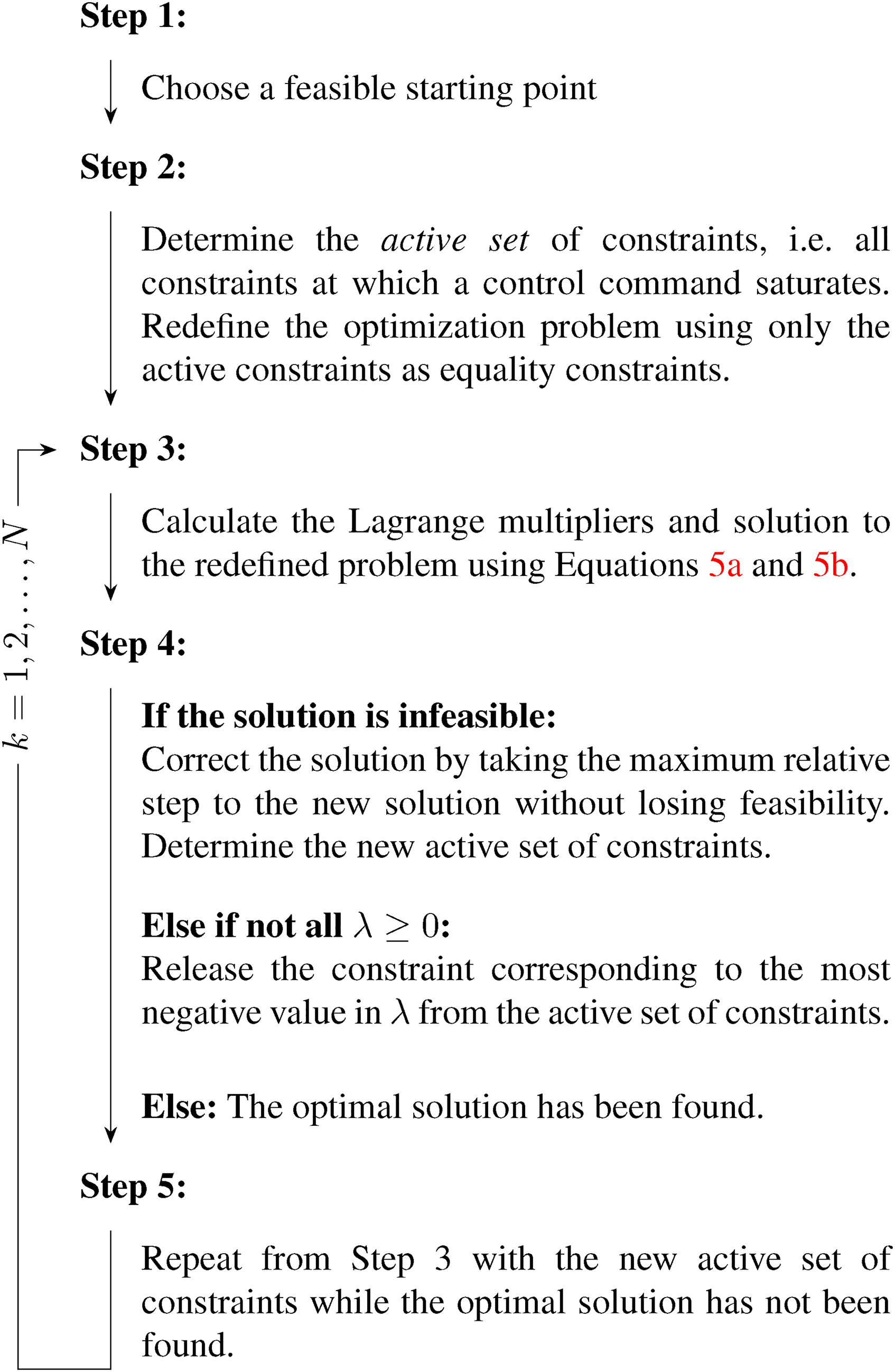
Active set method
Choosing a suitable starting point for the Active Set Method has a significant effect on the solver’s efficiency. In control allocation, each solution is likely to be in the neighborhood of the solution of the previous time step. The Active Set Method has a relatively low computational cost, 32 and since the solution progresses towards the final solution each time step, even when cut off before reaching the optimum to save computational time, the solution will be close to optimal.
XINCA
To simplify the outer loop control, hybrid UAVs like quadplanes are often controlled in either a vertical, horizontal or short transitional flight mode. Separating these flight modes however often results in sub-optimal flight control, not always using the most effective or efficient actuators nor making use of redundant actuators in case of actuator saturation. Worse even, actuator sets can even counteract each other. In hover, for instance, a downward pitch to move forward with a non-zero wind will cause a negative lift of the wing counteracting and possibly saturating the hover motors.
To solve this, a new control scheme is proposed, called Extended Incremental Non-linear Control Allocation (XINCA). It is an extension of INCA which takes the specific quadplane outer-loop dynamics into account as additional constraints. As shown in Figure 7, a linear controller on the position errors selects the desired linear reference accelerations. The error between these reference accelerations and measured accelerations then enters the XINCA optimization block. Like the INCA optimization, the XINCA optimization possesses several constrained actuators to achieve this control demand. These XINCA actuators do not only include physical actuators of the platform, but also some of its attitude angles and its vertical thrust command. In this research, the XINCA output includes the tail pusher rotor command, the vertical thrust command, and the vehicle’s pitch and roll commands. The tail rotor command is directly fed to the tail rotor itself. The thrust command and two attitude angle commands serve as input for the inner loop’s INCA optimization. The XINCA optimization is also performed with the Active Set Method. Since the effectiveness of the XINCA actuators is dependent on the aircraft’s states, it needs to be re-assessed at every iteration. But the resulting controller does not need to differ anymore for any of the flight regimes or flight modes.

A schematic representation of a XINCA controller (x = state vector, v = virtual input,
Implementation
XINCA is implemented in the open-source drone hardware and software platform Paparazzi UAV. 33 The quadplane itself makes use of a Lisa/MX autopilot board. Since this flight controller can control a maximum of eight actuators, the two ailerons share one control command, making them respond symmetrically yet in the opposite direction while reducing the computational cost of the INCA optimization.
The INCA module in Paparazzi UAV is based on an INDI module from Smeur et al.
27
and used by Smeur et al.
14
It is extended to include seven of the quadplane’s eight actuators, and scale the effectiveness of the three actuators that are aerodynamic surfaces, i.e. two separate ruddervators and the combined ailerons. The control is calculated as follows:


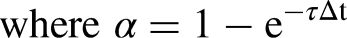
Since the actuators do not provide any form of feedback, an estimation of the current actuator deflection is performed each time step. This is done by a first-order approximation with a time constant


The XINCA controller works similarly to the INCA controller and is based on an existing outer loop INDI module by Smeur et al.34,35 This existing module uses the vertical thrust vector to control the position, by either changing the thrust itself or changing its orientation by pitch or roll increments. It is augmented by including a tail rotor command as the fourth actuator. The control is then calculated as follows:


Flight Simulations
To demonstrate XINCA’s performance, several simulations are performed. These are executed within the Paparazzi UAV software while using the actual code that will also fly onboard the quadplane.
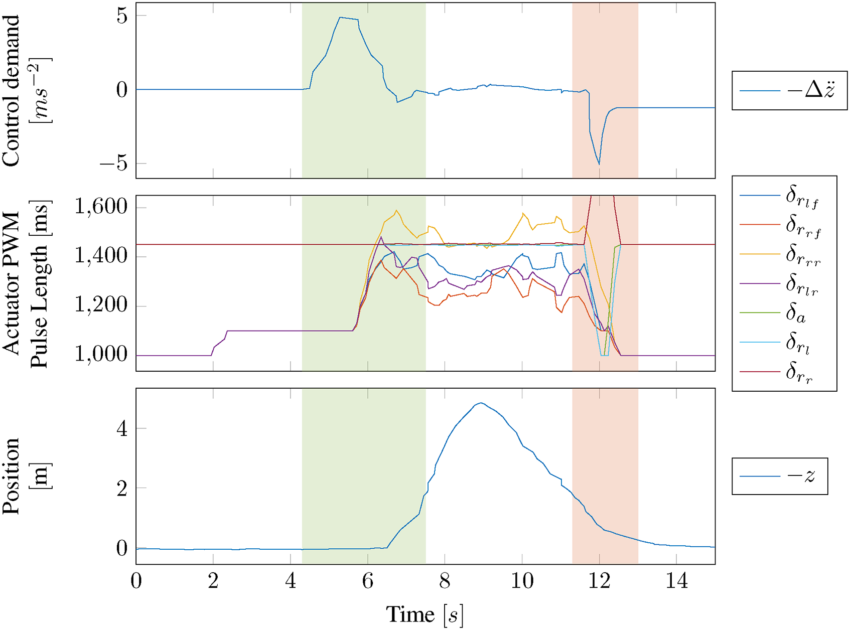
Figure 8 shows a simulation of a quadplane taking off (green) and landing (red). The top plot shows the control demand the INCA controller aims to achieve. The middle plot shows the resulting actuator commands expressed in PWM pulse length. The bottom plot shows the height profile of the flight.

Simulation of vertical quadplane takeoff and landing using XINCA and INCA with five actuators
To assess how well the INCA controller handles actuator saturation, a second simulation is performed with an artificial upper actuator limit slightly higher than the nominal throttle level needed for hovering. The result can be seen in Figure 9, which shows that saturation occurs during takeoff. The INCA controller achieves stable flight since its pitch and roll commands are prioritized above its thrust and especially yaw commands.
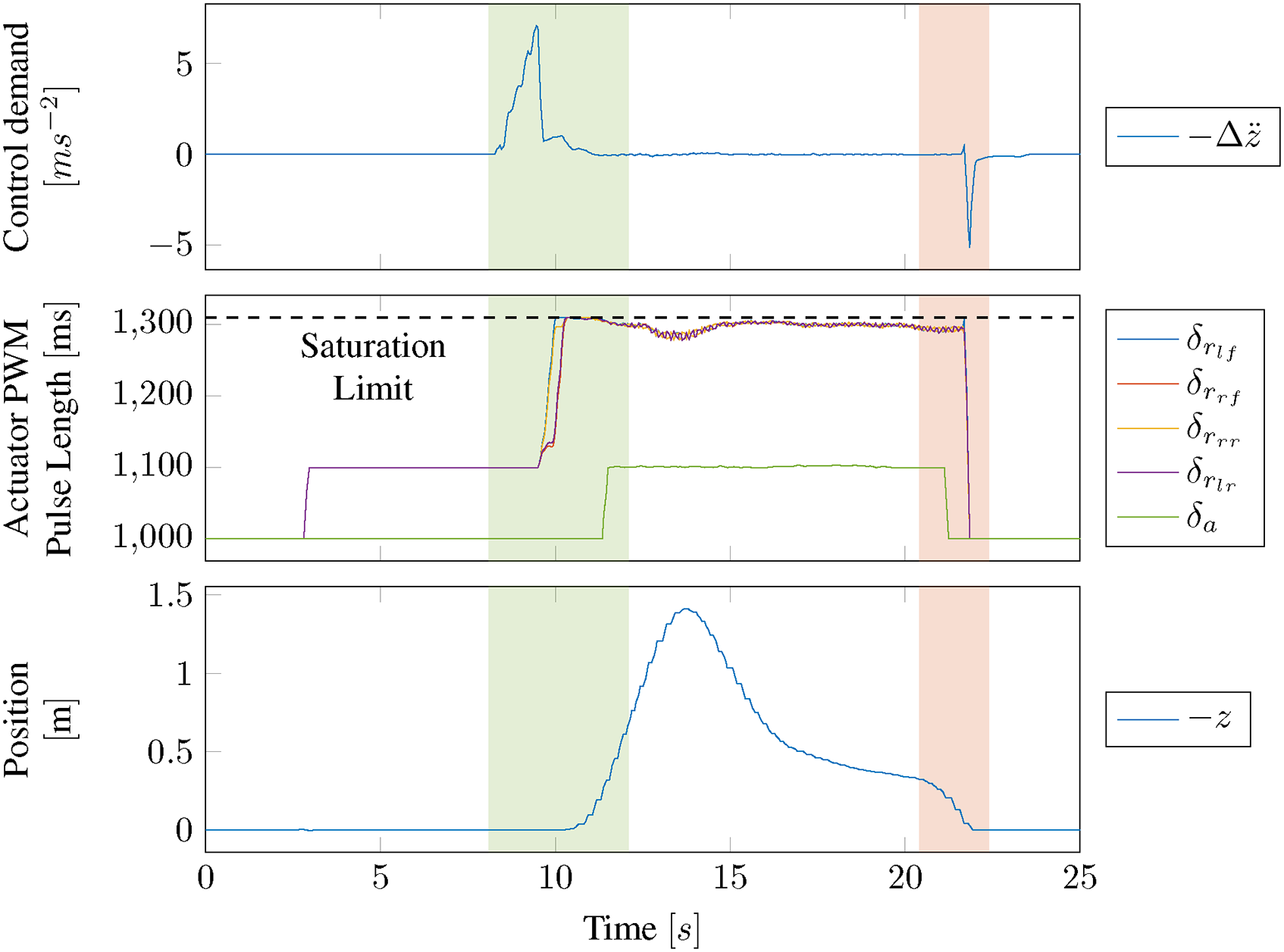
Simulation of a vertical quadplane takeoff and landing with actuator saturation occurring at an actuator Pulse Width Modulation (PWM) pulse length of 1310 ms using XINCA and INCA with five actuators
In the third simulation, the UAV moves forward and backward. Figure 10 shows the control demand and position in the

Simulation of forwards and backward flight using XINCA with both pitch increments and tail rotor inputs and INCA with five actuators
Two last simulations are performed to illustrate the benefits of using XINCA over conventional outer loop control methods. Both simulate forward flight of the quadplane and compare a traditional INDI outer-loop controller34,35 with the novel XINCA controller. Using the main wing’s aerodynamic properties in combination with the quadplane’s pitch angle and forward velocity, an estimation is made of the wing-induced lift force. Figure 11 shows the actuator commands, pitch angle, and lift force for both simulations. The most important difference can be seen in the pitch angles. Where the INDI controller pitches forward to achieve forward acceleration, the XINCA controller minimizes this negative pitch by using its tail rotor. This difference is reflected in the lift force estimations shown in Figure 12, where the XINCA controller manages to avoid the negative lift caused by pitching forward. At higher wind speeds, the negative lift can become very significant and result in hover motor saturation and possibly dangerous loss of altitude or even loss of attitude control.
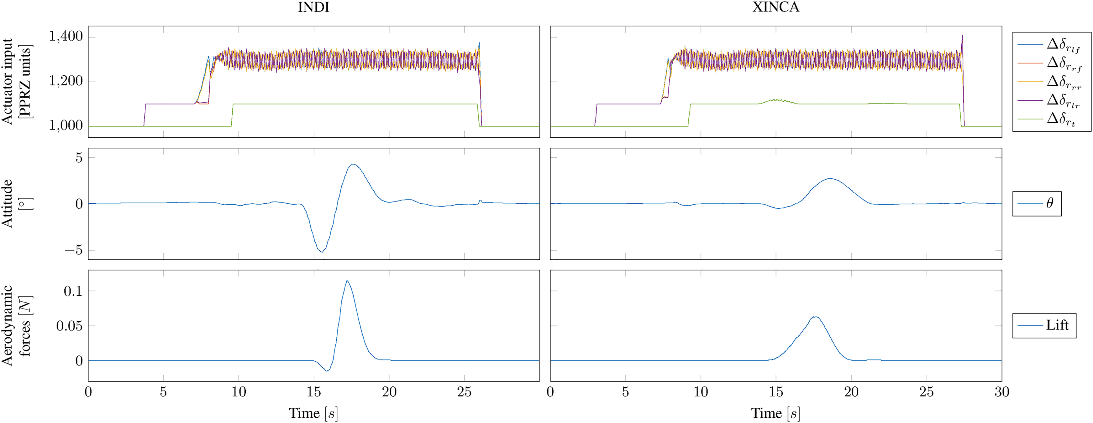
Flight data comparison of forward flight simulation with INDI and XINCA
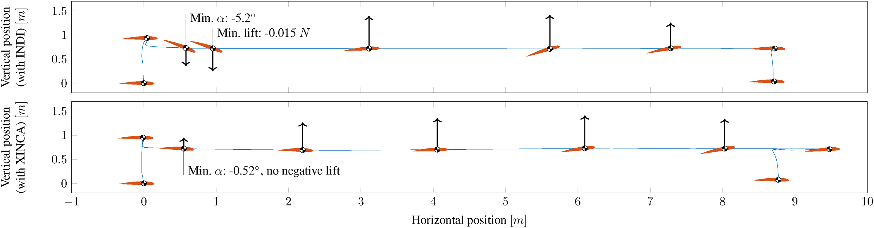
Flight profile comparison of forward flight simulation with INDI and XINCA showing wing-induced lift estimations. Note that illustrated angles of attack are magnified and force vectors are scaled for readability
Flight Experiments
The XINCA controller was tested in real flight tests of the TUDelft quadplane shown in Figure 1. The flight tests are performed in the CyberZoo, which is equipped with an optical position tracking system for precise vehicle positioning.
During initial attempts to fly the Quadplane with both the INCA and XINCA optimizations, the 32-bit STM32-F4 CPU processor running at 266 MHz could get overloaded. The first measure to reduce the computational cost of the controllers is to run the optimizations of both the inner and outer loops only once every second iteration of the autopilot, which runs at a cycle frequency of 512 Hz.
A system monitoring module in Paparazzi has been used to estimate the autopilot’s CPU loads with different configurations using this reduced optimization frequency. These configurations include a combination of the INCA controller with a lower cost outer loop controller, a combination of a lower cost inner loop quadcopter controller with the XINCA controller, and a combination of both the INCA and XINCA controllers. For configurations using the INCA controller, the amount of INCA actuators is varied to determine its effect on computational cost. The results of these measurements can be seen in Table 1. These measurements are obtained on the quadplane itself, yet without flying.
CPU load estimations for different inner and outer loop controllers with different numbers of INCA actuators
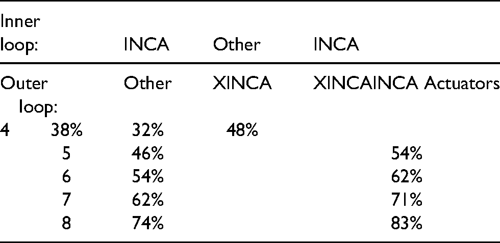
Because of the Active Set Method, the numbers clearly show a quasi-linear correlation between the number of actuators and the CPU load, and that the configuration with both INCA and XINCA does indeed demand a lot of the autopilot’s computing power. The actual load during one optimization cycle might however require significantly more computing power. Since the implementation was done on an older code base without an operating system, this could result in unpredictable behavior of the quadplane. Especially some time-critical processes could get in trouble under high CPU load. Ideally, the quadplane’s autopilot board is to be replaced by one with sufficient computing power. For this research, however, flight tests will be performed with either both INCA and XINCA without any control surfaces or INCA with all inner loop actuators and a low-cost outer loop controller.
The first test flight aims to confirm that the INCA controller chooses suitable actuators during flight. All inner loop actuators are included in the optimization. Since the CyberZoo’s confined space only allows for low-velocity testing, the controller is not expected to allocate a significant amount of control to the control surfaces. The results in Figure 13 confirm this. They show varying inputs for the quadplane’s upwards facing rotors, due to a slight asymmetrical configuration, but successfully ensure a stable takeoff and landing. As soon as the Quadplane touches down, the ground reaction forces result in unreachable control demands. This causes the rotors to saturate, after which the control surfaces are saturated as well in a maximum effort to reach the setpoint.
Stable quadplane takeoff and landing using INCA with seven actuators
In the second test, INCA’s resilience against actuator saturation is being put to the test. The saturation level is chosen in such a way that one actuator saturates, in this case,

Stable quadplane takeoff and landing with actuator saturation occurring at an actuator PWM pulse length of 1460 ms using INCA with five actuators
The final flight is the one where the novel XINCA module is being tested. For this flight, the quadplane is controlled by both the INCA and XINCA controllers that together allocate control to a total of five rotors. The flight consists of a takeoff, forward flight, backward flight, and landing. Figure 15 shows that the quadplane effortlessly manages to perform this longitudinal maneuver. The tail rotor command shows that this actuator is indeed used for both forward acceleration phases as expected.
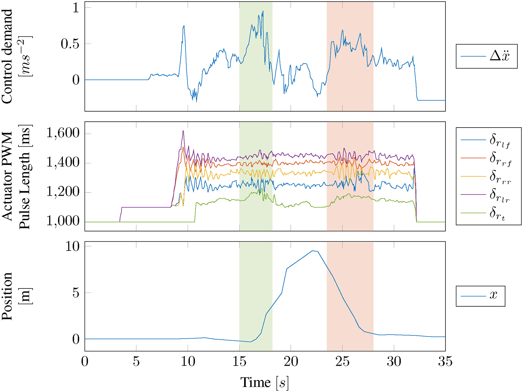
Forwards and backward quadplane flight using XINCA with both pitch increments and tail rotor inputs and INCA with five actuators
Conclusions and Recommendations
During both the simulations and the actual test flights, it was confirmed that the INCA controller chooses suitable actuators and achieves stable flight even in the case of actuator saturation. Prioritizing certain control demands over others plays an important role in maintaining stable flight when saturation occurs. Furthermore, the XINCA controller seamlessly takes the fixed-wing constraints into account in all flight phases without needing to switch modes. Furthermore, relying on the standard formula of lift, it does not require very a very detailed model of the vehicle. The efficient Active Set Method makes it suitable for real-time optimization at high frequencies (200 Hz in this work).
When optimizing commands for too many actuators, this INCA controller is not efficient enough to be used on 32-bit 266 MHz ARM micro-controllers. Allocating control to seven actuators while using a low-cost outer loop controller is at the edge of its computational capacity. Future research, therefore, requires either a gain in computational efficiency or hardware upgrades.
Finally, the novel XINCA controller is capable of performing optimization in the outer control loop by combining attitude angle commands as well as direct actuator commands. Recalculation of the actuator’s effectiveness at every time step allows a single controller to run across the entire flight envelope. This eliminates the inefficient use of separated flight modes while avoiding pitfalls like negative main wing lift in hover. This can contribute to a safer, more efficient, and therefore greener future of human aerial transportation.
Future research on the application of INCA on hybrid vehicles like the quadplane and the application of XINCA should focus on the performance during level flight, as this has not been sufficiently addressed in this work. Outdoor flights should serve two main research objectives. One objective would be to assess how the quadplane allocates more control to its aerodynamic control surfaces as soon as it has an amount of airspeed, making them more effective. The other objective focuses on XINCA, assessing its capabilities to adapt to the different dynamics of a hovering quadplane and one in forward flight.
Footnotes
Declaration of conflicting interests
The author(s) declared no potential conflicts of interest with respect to the research, authorship, and/or publication of this article.
Funding
The author(s) received no financial support for the research, authorship, and/or publication of this article.