
Abstract
The stability of small unmanned air systems can be challenged by turbulence during low-altitude flight in cluttered urban environments. This paper explores the benefits of a tandem wing aircraft configuration with the implementation of a pressure-based phase-advanced turbulence sensory system on a small unmanned air system for gust mitigation. The objective was to utilise passive and active methods to minimise gust-induced perturbations. Experimentation in repeatable turbulence within a wind tunnel’s test section was conducted. The experiments focus on the roll axis, which is isolated through a specially designed roll-axis rig. The results show improvement over conventional aircraft. This work is part of a larger research project aimed at enabling safe, stable and steady small unmanned air systems flight in urban environments.
Introduction
Small unmanned air systems (SUASs) or micro air vehicles (MAVs) typically operate at low altitude, within the atmospheric boundary layer. This region is optimum for a range of SUAS applications in intelligence, surveillance, and reconnaissance (ISR) missions and is characterised as having high turbulence intensity.1,2 In the presence of wind, SUAS performance can degrade significantly. 3 However, turbulence poses an even greater threat to the vehicle’s attitude stability.4–7 Consequently, attitude control in turbulence is a critical issue for SUASs and MAVs as identified by Mohamed et al. 8
A range of passive and active methods have been explored to address this issue of poor attitude control in MAVs. Passive methods involve the aircraft’s natural ability to produce the aerodynamic forces to achieve stability, through design features of the aircraft (e.g. wing sweep, dihedral, etc.). Existing literature show that these techniques can only attenuate limited frequencies of perturbations. 9 Active methods in contrast refers to the use of a control system, that goes through a sense (detect turbulence ahead of the aircraft), plan (consider desired control surface deflection ahead of time) and act (aerodynamic actuation) cycle, see Figure 1. It is near impossible to manually fly these aircraft in turbulence. 10 Many MAVs require control input rates beyond the bandwidth of human operators. 11 Employment of an active attitude control system is therefore vital as a micro-controller can provide higher input control rates than human pilots.

Control system’s process for controlling Small Unmanned Air System (SUAS) in turbulence, adopted from Murphy. 12
Active turbulence mitigation techniques utilise MEMS sensors, electro-optical sensors and GPS sensors as feedback sensors. However, these conventional sensors were found to be challenged by severe perturbations from turbulence inputs. 13 Active turbulence mitigation techniques have shown improved results when sensors with ability to detect the oncoming gusts are used.14,15 Phase-advanced multi-hole pressure-based sensors which are able to react to the turbulence ahead of the leading edge have been developed, 16 and these have been shown to increase the stability of SUASs in turbulence. 17 This paper explores passive and active methods of aiding the stability of SUASs through experimental wind tunnel testing of a tandem wing airframe, in conjunction with the phase-advanced multi-hole pressure probes, to further enhance the attitude control performance in high levels of turbulence. Roll perturbations were identified as the most significant disturbing factor for small fixed-wing aircraft1,9 and consequently will be the focus of this paper.
Tandem wings
The concept of a tandem wing aircraft is not a new one. Minardo and Trainelli 18 compiled a report with many examples of tandem wing aircraft which have been produced, noting how the first Wright Flyer in itself was partially a tandem wing, being a Canard configuration aircraft. A tandem wing aircraft is described as being an aircraft with two independent lift generating wings, which eliminates the need for a conventional horizontal tail and elevator. In order for it to remain a true tandem wing aircraft and not a canard aircraft, both wings must be of similar wingspans, and they will generally be set on different planes separated vertically and/or horizontally. It should be noted that although many different civilian tandem wing aircraft have been built over time, the design has not become popular. In recent times, the tandem wing configuration has started to make a resurgence. Unmanned aircraft can potentially benefit from a tandem wing configuration and it has been implemented successfully in various aircraft (e.g. ADCOM Systems Yabhon, Aeronvironments Switch Blade and Innocons MicroFalcon).
There have been various studies on Low Reynolds number tandem wing airfoils, such as literature19,20 which primarily looked at optimisation of a tandem wing design, but not in relation to flight through high levels of turbulence. The tandem wing configuration has a number of hypothesised advantages with respect to counteracting turbulence and when used in conjunction with the phase-advanced multi-hole pressure sensor system, as outlined in Figure 2. They are well suited for precision active control through the control surfaces embedded in its wings providing higher control authority and an added degree of freedom (heave). Heave is a translational vertical movement up or down, which is created by activating both the control surfaces on the front and rear wings to an extent which would provide an equal lift on both sets of wings, thus creating a heave motion. Heave has been identified as a common perturbation for SUASs and MAVs when in turbulence with length scales that are greater or equal to its wing span.8,21 The tandem wing design would appear to counter heave perturbations without the need to change the aircrafts pitch angle as much as is the case with conventional configurations. This can be particularly useful for on-board payloads which can be blurred due to rotational motion. Furthermore, the implementation of advanced pressure sensors14–17 on tandem wing designs has the potential to enhance the time advantage by allowing the placement of the roll control surfaces (ailerons) further aft of the probe sensors and enables a number of control architectures to be utilised.
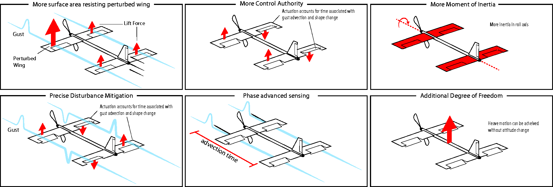
Tandem wing aircraft hypothesised advantages with respect to counteracting turbulence.
Vehicular development
A tandem wing aircraft has been developed (Figure 3 and 8), which utilises the phase-advanced multi-hole pressure sensors ahead of the front wings leading edge, as used in Mohamed et al. 17 The specifications of the aircraft are outlined in Tables 1 and 2. Due to the high frequency demands of stable flight in a high level of turbulence, high performance servos must be utilised for movement of the control surfaces. An all metal gear servo was selected, and the metal gears are necessary to allow for sustained high frequency and load movement of the servos without overheating. Specifications of this servo are outlined in Table 3.

Tandem wing small unmanned air systems in roll rig.

Conventional small unmanned air system in roll rig.
Aircraft specifications.

Aircraft component specifications.

RJX FS0435HV servo specifications.

A fixed span, flat-plate airfoil was selected for the experimental aircraft, and its performance in smooth flow has been documented by Mueller. 22
The sizing of the aircraft and its wings was made to be representative of typical SUASs which can be handled and launched by one person.
For the purpose of comparison, a fixed span flat-plate horizontal stabiliser of 40% of the main wing was used. This additional horizontal stabiliser replaced the rear wing, to represent a similarly sized conventional aircraft of the same wing span. This conventionally winged alteration of the tandem wing SUAS is shown in Figure 4.

Pressure-based cascaded PID control structure for the roll axis.
Control system
A custom-developed flight controller was used to control the aircraft’s attitude. The main components are a 32-bit ARM processor and an inertial-measurement-unit (IMU), which are required for the attitude estimation and real-time control implementation. A nonlinear complementary filter, presented in Euston et al., 23 is implemented to compute the aircraft’s attitude. In addition to the conventional IMU based control architecture, the differential phase-advanced pressure-based system as previously described is implemented to react to the turbulence ahead of the aircraft. This system has been outlined in Mohamed et al. 17 and is implemented by placing the differential pressure probes ahead of the leading edge of each of the front wings. The measured pressure is used as a feed-forward into the inner loop control system of the cascaded Proportional Integral Derivative (PID) controller, as shown in Figure 5, where Kff is the feed forward gain to be tuned experimentally.

Roll angle probe tuning.
Experimental setup
Passive turbulence generation, using planar grids, represented the most suitable method for producing elevated levels of turbulence intensity inside a wind tunnel. RMITs Industrial Wind-Tunnel (2 × 3×9 m test section) was considered sufficiently large to simulate the relevant turbulence conditions of varying length scales and intensities, and the aircraft in the tunnel with the turbulence grid can be seen in Figures 3 and 8. The approach outlined by Watkins et al.
24
is followed to characterise SUAS’s and MAV’s flight environment and replicate atmospheric turbulence. A Reynolds Number of
The primary focus of this paper is to compare the roll stability characteristics of the tandem wing aircraft with the pressure probes either active or inactive, with both the front and rear wing control surfaces acting as ailerons. Although for real flight of a tandem wing aircraft, the front wing may generally have a higher loading with the CG towards the front wing and thus some trim to the control surfaces would be needed, this study looks at the system with all control surfaces trimmed at a 0° angle.
The aircraft’s roll performance has been assessed through the aid of the roll axis rig detailed in Mohamed et al. 25 The rig constrains the motion of the SUAS to a single axis, that of roll, with low friction.
Aircraft control loop tuning
The roll axis PID gains were tuned in the selected experimental turbulence level of 12.6% via a process of trial and error, where the final selection of each gains value was selected by running the aircraft for 60 s over a range of estimated gain values, and analysing the resulting data, with the value selected which corresponded to the least roll angle and roll rate perturbations. As this is a SUAS operating in high frequency turbulence, the Derivative component of the PID controller is neglected, and this is because the derivative term amplifies noisy signals. 26 This can also be better for the servos, as it may reduce the demand placed on them by reducing the frequency of actuation commands. Only the Proportional and Integral components of the PID control loop are needed.
Probability density functions (PDF) and boxplots were used to analyse the aircraft’s performance while tuning in terms of roll angle and roll rate. The boxplot is a typical box and whiskers plot with a line for the median, ‘+’ for the mean, a box around the 25% and 75% quartiles and whiskers bounding 2.5% and 97.5%. The PDF plots can be interpreted such that a lower distribution and higher peaks corresponds to a reduction in perturbations of roll angles and roll rates.
A similar process of trial and error was followed when tuning the pressure sensor control loop gains, Kff. An example of this tuning is shown through PDFs and boxplots in Figures 6 and 7, whereby the Kff value of 25 was initially selected as the most appropriate value as it corresponded to the least roll angle and roll rate perturbations. After this initial range was tested, the range of values was further lowered until a more precise value was obtained.
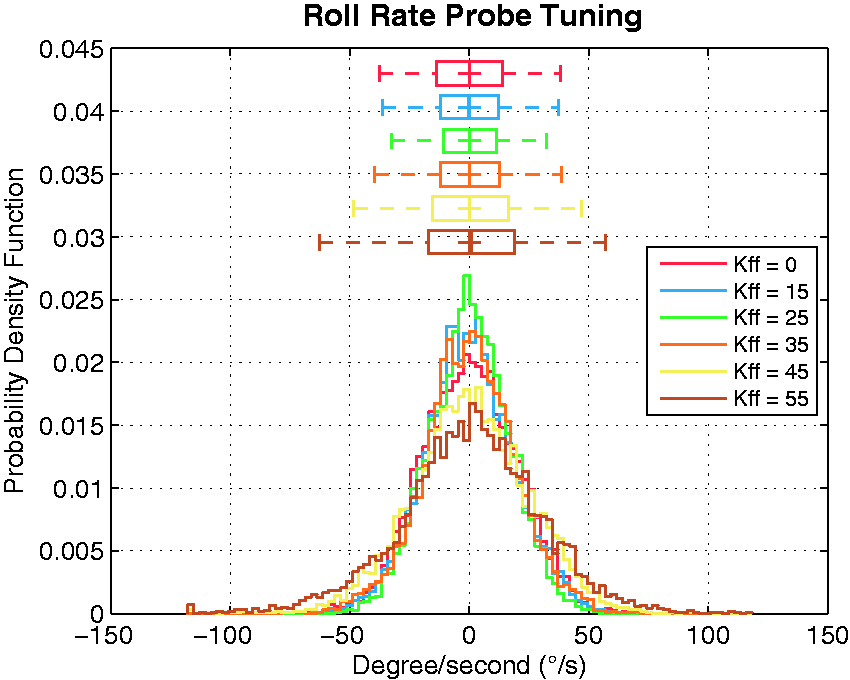
Roll rate probe tuning.

Tandem wing small unmanned air system in roll rig.
A similar process was followed for the conventional aircraft; however only the rate mode PID gains required change, with the attitude mode and probe gains able to remain the same.
Results
PDFs and boxplots were used to analyse the aircraft’s stability performance, where if the aircraft remained completely unperturbed in roll, the PDF plot would all be at 0°. Figures 9 and 10 show a comparison of the perturbations of the tandem wing and conventional aircraft in 12.6% turbulence intensity, with and without the pressure probe system activated in the control loop. It can be seen through the smaller box plots, higher peaks and lower distribution that there is a reduction in perturbations when the pressure probes are activated for both the tandem wing and conventional aircraft. Through similar analysis of the PDFs and boxplots, it can be observed that the tandem wing aircraft has lower perturbations in the turbulence compared to the conventional aircraft.
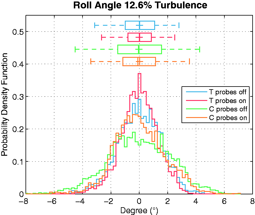
Roll angle perturbation of tandem wing (T) & conventional (C) aircraft with pressure probes off and on in 12.6% turbulence intensity.
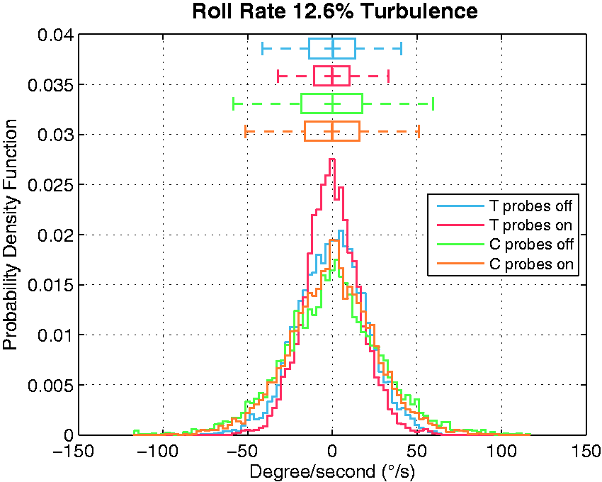
Roll rate perturbation of tandem wing (T) & conventional (C) aircraft with pressure probes off and on in 12.6% turbulence intensity.
In an effort to further explore the tandem wing aircraft’s stability performance in high levels of turbulence, testing was conducted in 18% turbulence intensity. PDFs and box plots of the aircraft’s performance at this intensity are shown in Figures 11 and 12. Much like in 12.6% turbulence intensity, there is a reduction in perturbations when the pressure probes were activated.

Roll angle perturbation of tandem wing aircraft with pressure probes off and on in 18% turbulence intensity.

Roll rate perturbation of tandem wing aircraft with pressure probes off and on in 18% turbulence intensity.
Conclusions
A tandem wing SUAS has been developed that is equipped with phase-advanced multi-hole pressure sensors to explore means of improving the attitude control in high levels of turbulence. Baseline performance and performance improvements have been demonstrated, emphasising the suitability of the tandem wing configuration in aiding safe and stable SUAS flight in turbulent urban environments. Much like past studies with conventional aircraft, utilising the phase-advanced pressure probes in conjunction with a standard PID control structure improves the roll stability of tandem wing SUASs in turbulence. Furthermore, it has been demonstrated that a tandem wing aircraft has lower roll angle and roll rate perturbations than a conventional aircraft with the same wing span in 12.6% turbulence intensity. Future work will explore varying control architectures and configurations (such as the studies with novel control surfaces designs by Panta et al.27,28), comparisons with different conventional aircraft set ups, along with testing without the aid of a roll rig, including testing of the tandem wing configuration heave and pitch characteristics in turbulence.
Footnotes
Acknowledgements
The authors wish to acknowledge the technical support provided by Gilbert Atkins at RMIT University for setting up the experimental instruments in order to conduct the presented research. This research was undertaken as part of the RMIT Unmanned Aircraft Systems Research Team, within the Sir Lawrence Wackett Aerospace Research Centre, at RMIT University.
Declaration of conflicting interests
The author(s) declared no potential conflicts of interest with respect to the research, authorship, and/or publication of this article.
Funding
The author(s) disclosed receipt of the following financial support for the research, authorship and/or publication of this article: This work has been partially funded and supported in part by the U.S. Air Force Office for Scientific Research (AFOSR); Defence Science and Technology Group (DSTG); Defence Science Institute (DSI); and the Australian Government Research Training Program Scholarship.