
Abstract
The aim of this work is to estimate the average wind influencing a quadrotor drone only based on standard navigation sensors and equations of motion. It can be used in several situation, including atmospheric studies, trajectory planning under environmental constraints, or as a reference for studying flights in shear layer. For this purpose, a small quadrotor drone with spherical shape has been developed. Flight data are recorded from telemetry during indoor and outdoor flight tests and are post-processed. The proposed solution is based on a calibration procedure with global optimization to extract the drag model and a Kalman Filter for online estimation of the wind speed and direction. Finally, an on-board implementation of the real-time estimation is demonstrated with real flights in controlled indoor environment.
Introduction
Estimating wind with a UAV has already been studied with multiple approaches. A common way is to use a fixed-wind aircraft and extract the wind from its GPS track 1 or by adding sensors on the system, such as 5-hole probe2,3 or a combination of simple Pitot tube and flags. 4 For a quadrotor, these approaches are not suitable, not only due to the non-constant inclination angles and flight directions, but also because of the low flight speeds. However, 5 compared the use of four different anemometers on a quadrotor. The study revealed that a thermal anemometer could be used, at the cost of modifications to the UAV structure in order to place it far enough from the disturbances induced by propellers.
Instead of adding components on the UAV, an alternate solution is to estimate wind from the quadrotor motion,6–9. In 7 the different possible models are presented: static, kinematic or full dynamic. In addition, a methodology to extract the required parameters is presented. The propulsion system is characterized by a motor test bench in a wind tunnel experiment, while the drag is extracted from flights at constant GPS velocity in steady air. The observation is made that the drag is proportional to the relative airspeed. In6,10, experiments were led using a six-axis force balance, a very precise but fragile and expensive system. Finally, 8 presents a nonlinear observer able to accurately predict the wind components, using only low cost Inertial Measurement Unit (IMU) and ground speed measurements. The drag-force is considered proportional to the rotational speed of the motors, that is almost constant during operation, leading to a constant rotor drag coefficient, similar to7,11,9,7 have performed outdoor flights and compared the results with ground reference measurements, demonstrating the feasibility of wind measurement from quarotor based on IMU and GPS measurements. The general principals and equations of motion from these studies have been used as a starting point for the present article.
This paper is organized as follows. First, the problem modeling focuses on the equations of motion, the hypothesis and limitations, as well as the experimental airframe. Then, the parameters identification method is presented and after that, the wind estimation with a Kalman filter is exposed. Finally, in-flight experiments are described and their results are analyzed.
Problem Formulation
Kinematic and Dynamic model
With the assumptions that:
the center of gravity (CG) is located at the center and origin of the body frame the frame and the propellers are rigid the inputs of the system are the thrust generated by the motors the outputs are the position and orientation of the body frame relative to the earth (inertial) frame, observed by the GPS and IMU sensors equation 1 represents the wind triangle
a simple dynamic particle model can be established as in
7
, leading to:
Finally, the last assumption is that the wind speed is seen as a constant or slowly varying disturbance, therefore the derivative of the wind triangle (equation 1) gives:


Aerodynamic frame with angle of attack
However, the experimental results presented in the calibration section show that in the range of the considered wind speeds, the rotor drag or H-force (see
11
) that is linear with the airflow seems to be dominant, hence:

The control force vector

Airframe characteristics
A custom quadrotor frame have been designed for this experiment. It is a simple cross shape made of thin aluminum bars to hold the motors and a spherical 3D-printed central body around the electronic components and the battery, as seen on the Figure 2. The reason for this choice is to have a symmetrical shape in order to reduce or eliminate the dependency between the generated drag and the heading of the drone.

Quadrotor with custom spherical body shape.
The general characteristics and components are summarized in the Table 1. The autopilot software used is the Paparazzi UAV System. 12
Quadrotor characteristics.

Calibration methodology
Estimating the wind from the quadrotor motion requires to estimate the drag parameters. The methodology applied is similar to
7
with the measurement of the bank angles

Quadrotor during calibration in from of the WindShape wind generator
The dynamic equation 2 in equilibrium state, illustrated by the Figure 4, directly provides a measurement of the drag force from the bank angle and the mass. Without loss of generality, the vertical component of the thrust compensate the weight and the horizontal thrust compensate the drag:

Side view of the forces applied on the quadrotor model in presence of horizontal wind.
The calibration procedure is as follow:
start the wind generator and measure the reference wind speed with an anemometer (hot-wire in our case) takeoff and place the quadrotor at a distance corresponding to the reference measurement when stabilized, change the heading to make one or more full turn on itself record the attitude ( repeat the procedure at a different wind speed
For each reference wind speed, a fitting algorithm is used to map the relation between the bank angles (

Roll angle
Similar results are obtained for 
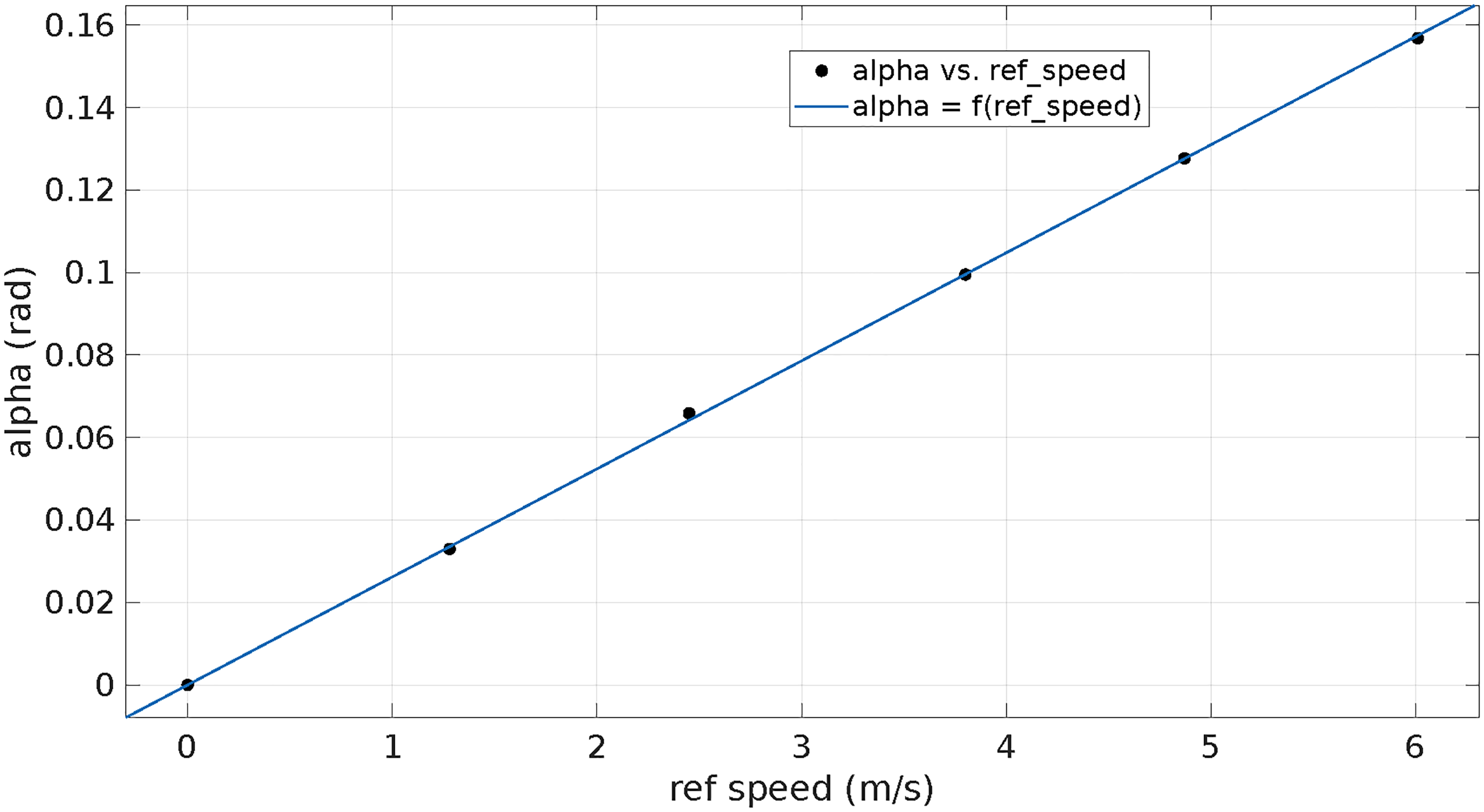
Relation between the incident angle
Wind estimation with Kalman filter
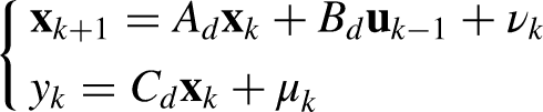
This problem considers simultaneous estimation of
All the sensors embedded are low-cost, and therefore have imperfections. The major error sources in the navigation system are due to: - all of the disturbances (noises) that affect the instruments; - the potential incorrect navigation system initialization (e.g. on magnetometers sensor); - and the inadequacy between the real local Earth’s gravity value and the one used for computation. The largest error is usually a bias instability (expressed respectively in deg/hr for gyros and
Using these values, the state space representation corresponding to 

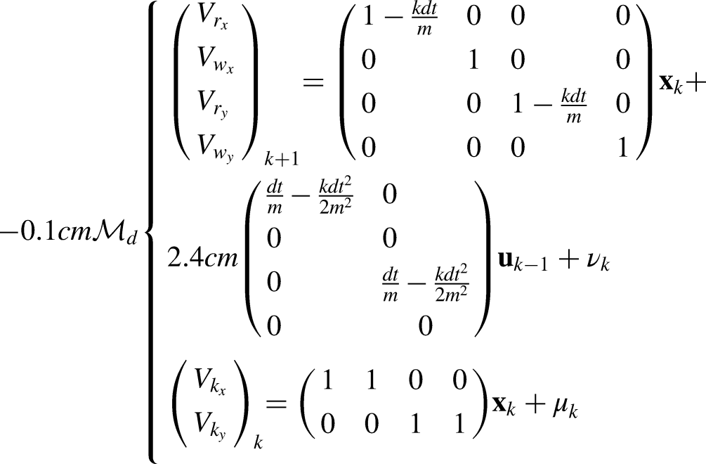
In the later experiments, the process noise relative to airspeed evolution is
Experimental flights
Indoor flight in controlled wind speed
The wind estimation algorithm is first evaluated with a flight indoor in front of the wind generator used for calibration. The goal is to evaluate the stability and convergence of the estimation in a controlled environment. In this setup, the wind is coming from a virtual north and the quadrotor is hovering at a fixed position. Ground speed and orientation are recorded from the telemetry and post-process by the Kalman filter in a Matlab script.
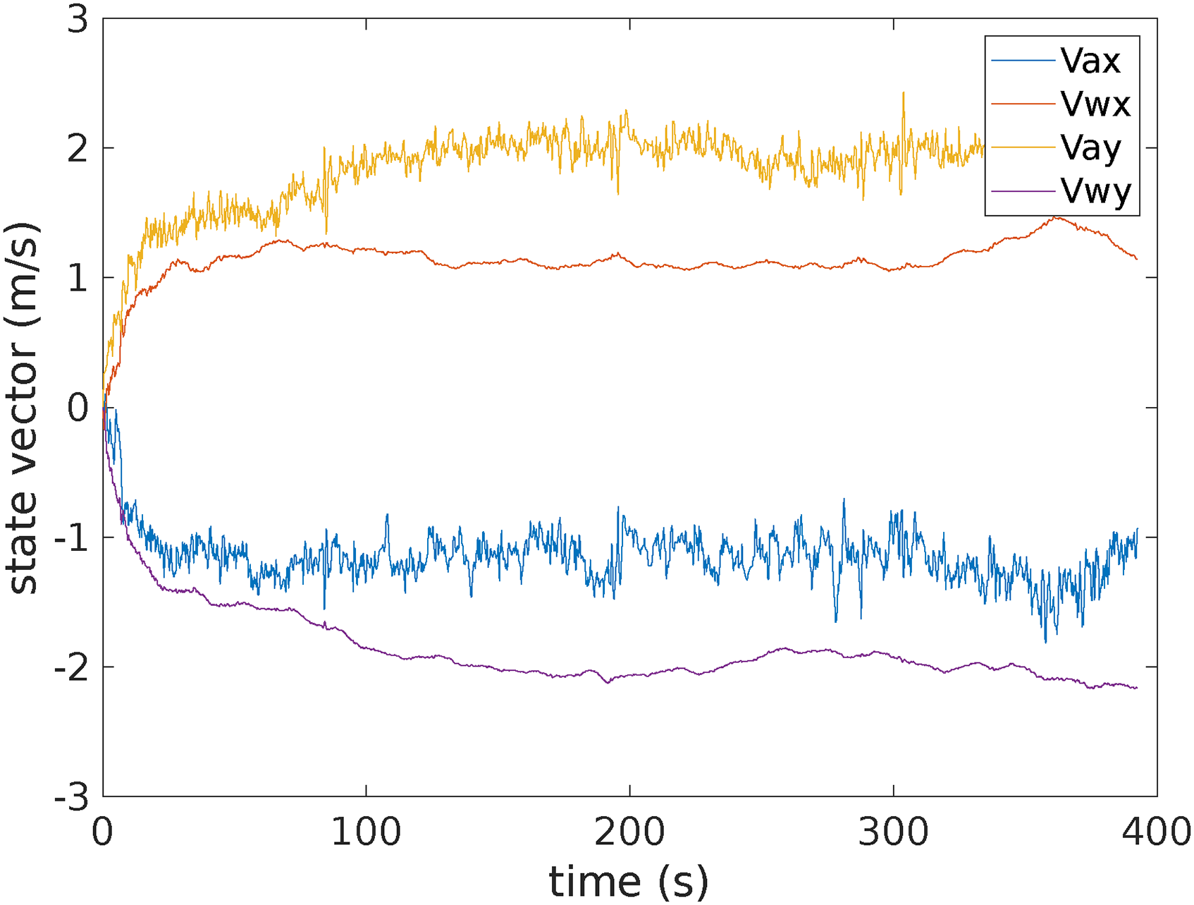
Figure 7 shows the four elements of the state vector. The convergence time is around 10 to 20 seconds. The noise on the estimated airspeed is low thanks to the low noise on the measured ground speed (from motion capture) and the stable airflow.
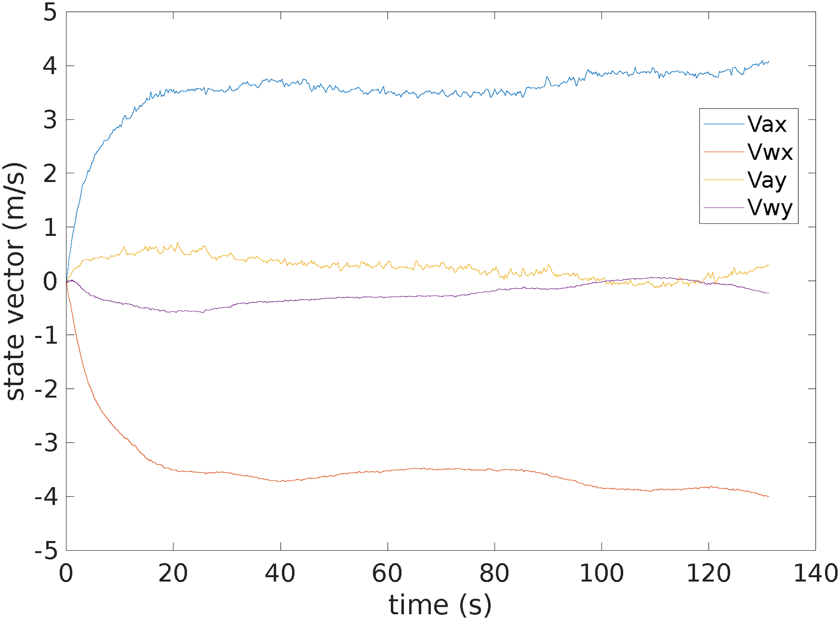
Evolution of the Kalman filter state vector over time during indoor flight.
Figure 8 is the norm of the estimated wind speed
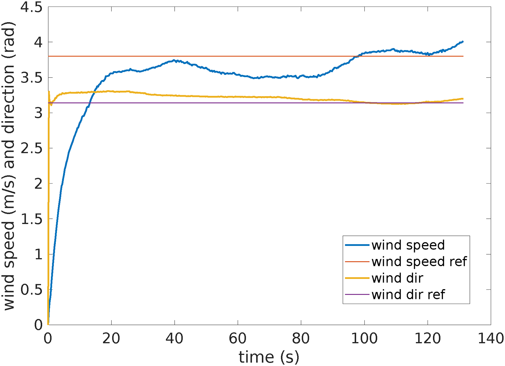
Wind speed and direction compared to the reference value from the wind generator; wind is coming from a virtual north (
Outdoor flights
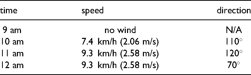
Several flights have been performed outdoor to record telemetry data, with attitude from IMU and this time ground speed from real GPS sensor. Only two relevant flights are presented in this paper. They were performed at Muret’s model airfield (close to Toulouse, France) on the 20th of May 2021. The wind conditions for that day are coming from public meteorological data and are reported in Table 2.
Wind condition on the day of the outdoor experiment.
The first flight corresponds to the vertical profile (red trajectory on Figure 9). The quadrotor goes up and down at a vertical speed of 1 m/s and with the heading changing at constant rate. The horizontal speed is close to zero. The state vector evolution is plotted on Figure 10. As expected, the noise on airspeed estimate is stronger than during indoor experiment due to sensor noise, but still acceptable.

Trajectories for the outdoor flights: vertical profile in red, horizontal square at constant altitude in blue.
Evolution of the Kalman filter state vector over time during outdoor flight (vertical profile).
The vertical flight was done a bit after 10 am, so according to Table 2 between 2 and 2.5 m/s, with a direction between 110

Wind speed and direction compared to the reference value from public meteo data during the outdoor flight (vertical profile).
The second flight is a square (blue trajectory on Figure 9) at low altitude. As a consequence, the ground speed is changing, with horizontal acceleration when changing direction. These variations can be seen in the airspeed vector on Figure 12. The wind vector is also showing some variations and is less stable than with the previous case.

Evolution of the Kalman filter state vector over time during outdoor flight (square trajectory).

Wind speed and direction compared to the reference value from public meteo data during the outdoor flight (square trajectory).
The square flight was done at 9:30, so according to Table 2 between 0 and 2 m/s, with a direction around 110
Onboard implementation
An onboard real-time implementation have been developed within the Paparazzi autopilot (previous results are post-processed from logged data), directly inside the flight controller. This section presents the results of this filter during an indoor flight test in front of the wind generator.
The experiment is decomposed as follow:
take-off and standby at 3 meters in front of the wind generator after around 100 seconds, the wind generator is activated at 40% (3.8 m/s) at 200 seconds, the quadrotor moves back to 7 meters away from the wind generator (the generated wind speed reduces to 2.8 m/s at this location) at 225 seconds, it goes back to the initial position after 250 seconds, the wind generator is shut down and the quadrotor stays in hover.
Figure 14 shows the reference wind speed and the estimated airspeed. Each time the frame is moving (marked by the two arrows), the norm of the airspeed is presenting a spike corresponding to the wind plus the relative wind due to motion.

Evolution of the airspeed estimated from onboard filter and the reference wind speed.
Figure 15 and 16 are showing the estimated wind speed and direction respectively. Several considerations can be made from these plots. First, the convergence time is around 20 seconds, just like the data analyzed from log. Second, the estimated values converge to the reference values when the wind generator is activated. However, an error is observed during the hovering without wind. This error on the direction is not relevant since at zero wind speed this parameter is meaningless. On the other hand, the non-zero value for the norm of the wind during the first and last phases reveals a static error in the filter. It can be explained by the fact that the average bank angle coming from the state estimation is around

Evolution of the wind speed estimated from onboard filter and the reference wind speed.

Evolution of the wind direction estimated from onboard filter and the reference wind direction.
Finally, the onboard implementation shows acceptable performances and is light enough to run on the flight controller directly. The estimated wind and airspeed can then be used to improve the control and the trajectory planning. The code is integrated to the main repository of Paparazzi autopilot under GPLv2 license.
Conclusion
A wind estimation filter based on the orientation and ground speed of a quadrotor have been presented. Experimental flights were conducted to compute the calibration parameters of the model and validate the results in controlled indoor flight, as well as outdoor conditions.
An implementation of the Kalman filter in the flight controller of the autopilot provides on-board real-time estimation. Such information can be useful to improve navigation or even state estimation.
Future work will be focused on the influence of parameters such as the mass, the aerodynamics of the main body or the propeller size and rotation speed. The calibration procedure should be compared to flight log analyzes to allow identification of drag parameters without motion capture and wind generator. Finally, the online estimation of the drag coefficient should be considered, taking into account the conditions under which this parameter is observable.
Footnotes
Acknowledgements
This work have been done using the preliminary work and calibration experiments of Laurent Hublet, Maxime Vacheron and Carl Guilly, students at Enac, during their second year project under the supervision of the authors.
Declaration of conflicting interests
The authors declared no potential conflicts of interest with respect to the research, authorship, and/or publication of this article.