
Abstract
For micro air vehicles (MAV), the precise prediction of aerodynamic force plays an important role. The aerodynamic force of a comparative low Reynold number (Re) vehicle tends to be affected by the different flow modes. In this paper, the aerodynamic performance of a three-dimensional NACA0012 airfoil is studied numerically. A range of angles of attack (α) 0°−25° and Reynolds number 1000 is considered. Mean and fluctuating coefficients of aerodynamic forces around NACA0012 airfoil are analyzed for different wake modes. The difference of aerodynamic forces between two and three-dimensional simulations are compared. The results show that the wake remains steady two-dimensional for lower angles of attack. At α = 9°, Von Karman vortex pattern is noticed. Flow transition to three-dimensional as the angle of attack increases from α = 13°. 3D wake is found to be stable with parallel shedding mode for 14°-17°. However, these modes become finer with the gradual increase in angle of incidence. While, wake loses its three-dimensional stability to chaotic with gradual increment in angle of attack afterwards.
Introduction
MAVs generally work at a comparatively low Reynold number, which suggests the viscosity of fluids play a competitive role with the inertial force. Flows over a foil have extensive application in MAV, as well as marine engineering, energy harvesting, and so on. For example, the movement of an airfoil under an incoming flow plays a significant role to wind energy harvesting for both inshore and offshore wind farm. By using aerodynamic force to drive the mechanical moving of airfoil is among the most frequency applied and reliable technologies to extract sustainable energy. Airfoil as lifting surface is widely applied to lots of aircrafts as well as marine equipment in order to balance buoyancy/gravity or manipulate the gesture of vehicle. In more and more situation, airfoil are frequently applied for small size equipment such as MAV and autonomous underwater vehicle (AUV). As the decreasing of size, turbulent motion of fluids are rarely came into play, which may generally stabilize the system. However, as the fluid viscosity plays more important role, the competitive behavior between viscous and inertial force make the flow mode complicate or lead to the abrupt transition of aerodynamic force.
Flow dynamics over airfoil are highly dependent on shape of object and freestream parameters, which are mainly parameterized as Reynolds number and angle of attack. Wake behind streamlined bodies remains stable as Reynolds number increases up to a certain critical value. Slight increment in critical Re alters stable configuration to unsteady. To understand the characteristics and behavior of oscillatory forces, a number of research efforts have been directed for decades.1,2 Especially subcritical region is swayed by Re where laminar separation is dominant. Low Reynolds number aerodynamics has notable importance in transition of flow from laminar state to turbulent state. At small angle of incidence and low Re, flow remains laminar having thick shear layer over airfoil. Flow separates near leading edge (LE) in presence of high adverse pressure gradient in region. Increment in angle of attack leads flow separation near trailing edge (TE). As a result, separation point moves toward upstream of airfoil which causes increment in width of wake. Increase in width implies increase in drag coefficient and decrease in Strouhal number.3,4
For assessment of aerodynamic characteristics: attached flow, separation vortex, TE vortex, LE vortex and blunt body effect, several experiments have conducted in water tunnel by Huang et al.
5
and Mahbub Alam et al..
6
Particle image velocimetry (PIV), Particle tracking velocimetry (PTV), Laser doppler velocimetry (LDA) and Laser-induced fluorescence (LIF) measurements are employed to investigate the dependence of these characteristics to angle of incidence for low and moderate Reynolds number. The flow around an airfoil at Reynolds number < 105 is sensitive to the boundary layer separation results in the lift coefficient reduction. Nonlinear variation with respect to for NACA0012 for chord Reynolds number (Rec)is studied.
7
Dramatic increase in the lift coefficient for
With the development in technology, several methods are introduced to achieve better accuracy regarding separation, reattachment of boundary layer and transition for simple flows. Kurtulus3,4 has conducted study on the unsteady behavior of flow around a 2D NACA0012 foil numerically. Reynolds number 103 and angle of incidence ranges from 0°-90° were considered for simulation. Vortex splitting is observed for α = 23°−41°. Additionally, for α ≥ 50°, vortices emergence to form single Karman vortex before shedding to wake with time is noticed. Although two dimensional results are found to be worthwhile for revealing some flight mechanism, 8 extensive literature on three dimensional wake transition for flow past bluff bodies through direct numerical simulation (DNS) methodology suggest that the aerodynamic force is sensitive to the transition to the three dimensionality of wake. Through various investigations, it has shown that flow in the wake of blunt bodies undergoes a transition sequence of primary wake instability to three dimensional instabilities,9–12
During the transition from two to three dimensional wake for the secondary instabilities regime, mode A (spanwise wavelength of 4d) and mode B (spanwise wavelength of < 1d, d is diameter of cylinder), are reported for flow over circular cylinders and square cylinders.13–15 These flow regimes appear when symmetric wake is distributed by applying asymmetric conditions. Tong et al. 16 found mode A and B are present for six different angles of attacks. Spanwise wavelength of braids reveals dependence on angle of attack. Hoarau et al. 17 have used DNS to analyze three-dimensional NACA0012 at angle of attack 20° for Reynolds numbers 8×10²–104. Two kinds of organized modes in (i) Von-Karman for Re < 2×10³ (ii) shear layer mode for Re ≥ 2×10³ were reported.
Transition to chaos in the cylinder wake directly through three-dimensional instability mode C is studied recently. 18 Mode C is generated by placing a small wire in the wake at Re = 400. Another study has figured out that a wire of 1/100th of a cylinder diameter placed at position of five diameters upstream of the cylinder, sufficiently perturbs the flow to substantially affect certain wake transitions. 19 Balakumar investigated turbulent statistical quantities for Rec. 20 Angle of attack 5° with M = 0.4 for Rec = 50×103 and angle of attack 15° along with M = 0.2 for Rec = 106 respectively were chosen for investigation purpose. Based on DNS data study disclosed existence of complex flow features regarding flow over an airfoil: the laminar separation bubble on the suction side, a turbulent reattachment, and turbulent separation on trailing edge at two different angles of attack. Periodic doubling is identified at 22° which causes chaos at 27° during numerical analysis of 2D NACA0012 airfoil. The interaction of these foils shows dependent but more complicate flows behavior. 21 Disruption of laminar separation bubble to turbulence is simulated in several investigations.22–24 To model the flow over oscillatory airfoil, Wu and Xu have implemented boundary element technique. 12 Moreover, the effects of periodic motion aerodynamic coefficients and Strouhal number were explored.
Thrust and efficiency of 2D at plate airfoil in case of low Reynolds number is numerically determined. 25 Cutcell approach has implemented to manifest the both efficiency and thrust increase for different Reynolds number. Under low Reynolds number coupled with high angle of attack, flow is laminar and subject to separate even for low adverse pressure gradient. Vortical structure in the wake at low Re is of interest due to noise generation with variation in α. In the light of previous investigations, primary objective of this study is to provide the useful information about flow behavior over 3D NACA0012 airfoil at Reynolds number 1000, with the particular focus on the influence of asymmetric wake pattern appeared at high α. The selection of present Reynolds number 1000 is served as a represent, since the most of insects and their bionic MAV designs fly in the range of Re from 1000 to 10000. Furthermore, there are plenty of studies on the experimental and numerical study at such Re for comparison.3,4,26–28 One may expect that flow behavior with closed Reynolds number is similar but with variant critical angles of attack.
This paper is organized as follows: Section II presents the geometry and methodology used. Section III illustrates the instantaneous and mean behavior of aerodynamic forces along with the three dimensional wake flow. In the last Section IV, a brief conclusion is given.
Methodology
Geometry and boundary conditions
A symmetric airfoil NACA0012 of sharp trailing is used for computational purpose. NACA0012 with sharp trailing edge is defined by the equation combined with incompressible Navier-Stokes equations


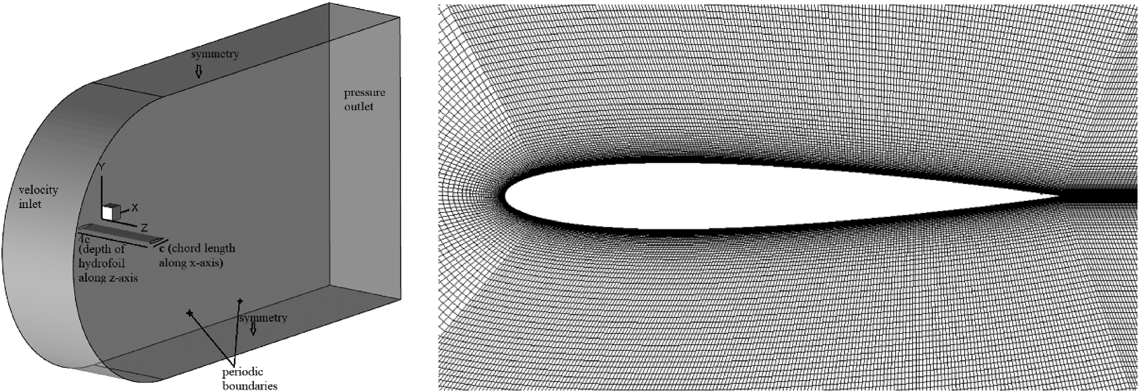
Schematic 3D model of computational domain (left) C-grid mesh topology around airfoil (right).
C-grid topology is used around airfoil. The spanwise length of the computational domain is 4c so that the spanwise flow structure can be fully considered, where c represents the lengths along chord of the airfoil. Also, (Lx, Ly, Lz) = (24c, 12c,4c) being domain dimensions along x, y, and z directions are adopted for simulation. Coordinates are non-dimensionalized by using chord length c. Uniform flow velocity Uinf is applied at inlet, in x-direction. At outlet, Neumann boundary condition as well as pressure is specified as a reference value of zero. To approximate the flow past bluff bodies of an infinite spanwise length, periodic boundary conditions have been usually employed in numerical simulations. 29 Top and bottom boundaries are considered as symmetric boundaries to avoid the thickness of no slip wall. While, no-slip boundary condition is applied on the surface of airfoil
Second order implicit discretization are utilized to discretize space and temporal domains of NS equations. Simulations are carried out at Re = 103 for angle of attack ranges zero to 20°. As angle of incidence increase, a number of phenomena can be observed (i) separation point on the suction side moves towards the leading edge (ii) the separated boundary layer is laminar. (iii) both cd and cl grow. This work aims to document the three dimensional structure in wake, lift, drag and pressure coefficients and their dependence on angle of attack and Re for a 4c depth of airfoil.
Mesh independence study
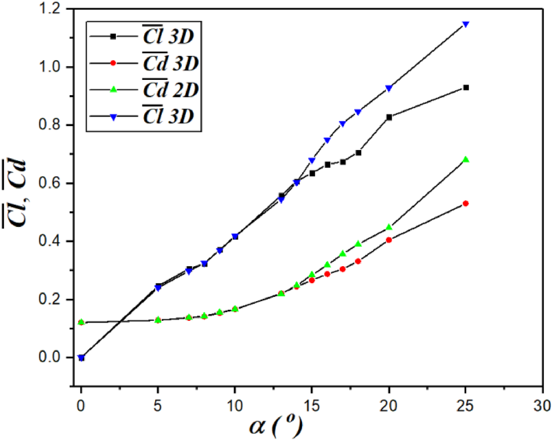
2D mesh is constructed at first and airfoil surface is discretized with 250 nodes. Height of the first layer mesh is kept at 0.0002c next to the airfoil surface, which corresponds to small enough non-dimensionalized wall distance of y+ = 0.02. A total of 0.198 million quadrilateral cells are used for two-dimensional mesh. Close up view of 2D grid system in vicinity of airfoil is shown in Figure 1(b). For benchmark, present results of mean coefficients of drag (Cd) and lift (Cl) with data presented in previous works are illustrated in Figure 2(a) and 2(b) respectively and found to be in good agreement with literature.3,26–28

Comparison between present results and literature (a) coefficient of drag and (b) lift coefficient for 2D geometry.
Three-dimensional mesh is constructed by extruding 2D geometry in z-direction, resulting in identical mesh of same resolution in all the planes normal to the spanwise direction. Cell size
Table 1 shows the results of averaged aerodynamic force and unsteady flow feature under the time-step and grid refinement for

Grid and time-step independence study for lift coefficient (upper) and drag coefficient (lower).
Time and grid refinement study for three-dimensional airfoil.

Furthermore, results are trivial in case of Strouhal number. Hence, M2 is considered sufficient fine for simulation. In addition, for chaotic flow appeared at
Results
Globe flow behavior and the difference between 2d and 3d simulations
In the present work, both 2D and 3D simulations for flow over NACA0012 are studied for angles of attack between 0°-25°. However, flows remain to be two-dimensional for lower angles of attack. Mean aerodynamic forces as well as instantaneous pressure distribution along upper and lower surfaces of airfoil are reported. As angle of incidence increased, the three dimensional instability of mode C is observed for a range of angles of attack with growing wavelengths. In case of three-dimensional flows, periodic doubling is observed for the two-dimensional simulations.
Firstly, computations are carried out at very low angle of attack for Re = 1000. Figure 4 clearly illustrates the instantaneous and time-averaged vorticity contours for flow over 3D configuration. Meanwhile, associated characteristic mean streamlines pattern for flow over 3D airfoil is presented in Figure 5. It is obvious that attached flow is observed for

(A)The instantaneous spanwise vorticity contours (b) time averaged spanwise vorticity contours for

Time-averaged streamlines for a range of low angles of attack at Re = 103.
In fact, flow exhibits two-dimensional characteristics and no difference in flow characteristics for 2D and 3D simulations for angle of attack lower than 14°. The transition of symmetric 2D wake to asymmetric wake pattern under adverse pressure gradient occurs at high angle of attack for Re = 103. Table 2 demonstrates the difference of mean drag and lift forces between 2D and 3D simulations occurs at high angles of incidence. In two-dimensional simulation, airfoil experiences greater lift and drag forces. For larger angles of attack, difference becomes more dominant. For instance, at
Comparison between mean values of aerodynamic coefficients of

In Figure 6, it is obvious that
Comparison between 2D and 3D mean aerodynamic forces for different angles of attack.
Additionally, comparison of shedding frequencies is also listed in table 2. Fast Fourier transform is applied at streamwise velocity component to analyze dominant and subharmonic frequencies for different angles of attack (Figure 7). f1 is main shedding frequency of dominant vortices in case of

Dominant and subharmonic frequencies at various angles of attack (a) 10° (b) 15° (c) 20° (d) 25°.
Pressure profile near the airfoil
To further discover the aerodynamics force, the instantaneous pressure profile
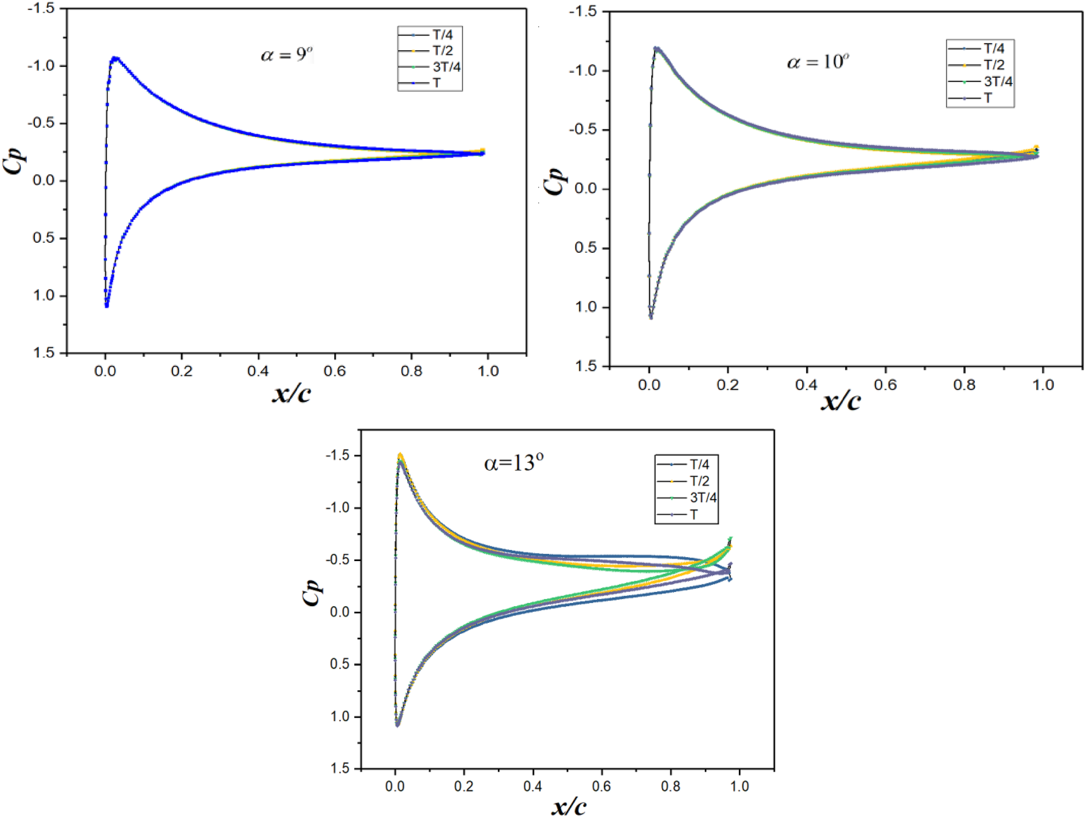
Pressure distribution along spanwise position z/c = 2 for different time periods.

Pressure distribution along the airfoil for various angle of attack.
Pressure distribution for mean

Mean Cp profiles for various angles of attack.
Discussion on the three-dimensional flow structures
Present simulations exposed the existence of three dimensional instabilities in case of flow over 3D airfoil. Development of three-dimensional instabilities from two-dimensional flow configuration are presented in this section. Vortical structures formed in wake of airfoil highly depends on angle of incidence. Angle of attack 14° is observed as critical angle due to flow transition to three-dimensional state. Till
To visualize the three-dimensional wake structure, here we define three non-dimensional vorticity values as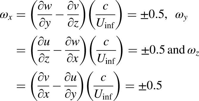
Figure 11 reveals the parallel large rows of Von-Karman vortices with growing spanwise wavelength for various angles of incidence. It is observed that the wake structure after the time interval T is antisymmetric and return to its original structure after 2 T. This is a signature of mode C instability, which was firstly observed and analyzed by Zhang both experimentally and numerically. 32 Detailed numerical study on mechanism and development of three-dimensional structures and its wake transition characteristics in the wake of inclined plate at = 25° were studied by Yang et al. for a range of Re from 350−500. 31 Results showed that spanwise wavelength of organized modes depends on Re as spanwise wavelength of 0.708d, 0.67d and 0.75d obtained for Re = 350, Re = 400 and Re = 500 respectively. 33
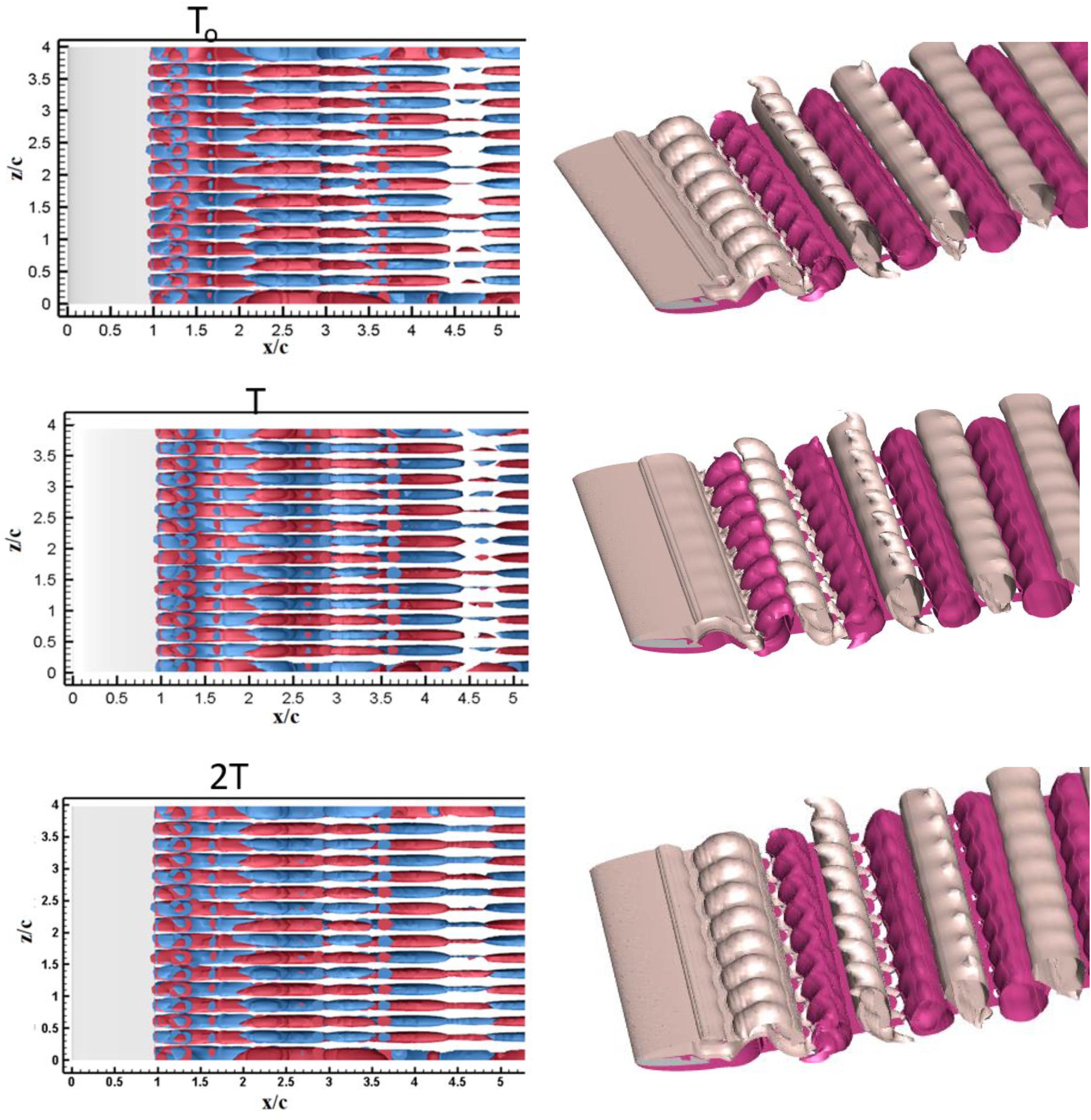
Mode C with time period 2 T at angle of incidence 15°(right). Perspective view of spanwise vorticity component to corresponding time interval (left).
In present study, braid like structures with small wavelength as shown in Figure 12 are visualized for

Top view of parallel modes C (a)
Further analysis demonstrates that the parallel modes appeared are mode C with a time period 2 T. 2 T is a most striking feature of mode C (where T being vortex shedding time period). Mode C is observed with iso-surfaces of

(A, b) symmetric pattren of global parameters at angle of incidence 15°. (c, d) assymtric pattern of global parameters at angle of incidence 17°.
Figure 11 shows the uniformly distributed braid like structures of instability mode C for angle of attach 15°. As angle of attack is increased further, vorticity components become stronger and start to perturb smoothly arranged braid like structures. Spanwise wavelength reached its maximum as shown in Figure 12(c). The variation of wake instability could sensitively affect the corresponding aerodynamic force and noise, which may lead to severe impact on the working performance of aerodynamic equipment. For the airfoils in MAV, it is therefore should notice that the angle of incidence could results in chaotic wake flow and rapidly varying aerodynamic force as the variation of its angle of attack. As angle of attack increases further, wake transition process becomes more complicated. Figure 14 demonstrates the irregular pattern of Cd and Cl for angle of attack 20° and 25°. Aerodynamic forces show random behavior. With increment in angle of incidence shear layer encounters instability after separation and became chaotic.

Top view of instantaneous iso-surfaces of streamwise vorticity (red and blue) and spanwise vorticity (green and yellow) along with irregular pattern of Cd and Cl (a-c) 20° (d-f) 25°.
As seeing the mean Cp profiles plotted in Figure 10, magnitude of pressure distribution at
For

Contour plots of temporal spanwise vorticity near wake of hydrofoil for various angles of attack (a-d) two-dimensional simulation (e-h) 3D simulation. (a) and (e)
Concluding remarks
In this study, direct numerical simulations of moderate Reynolds number are carried out over 3D NACA0012 airfoil. Various instantaneous and time-averaged aerodynamic parameters including coefficients of lift, drag and pressure are calculated. Development of 3D transitions of wake and robustness of parallel Von-Karman vortices are analyzed with varying angle of attack at fixed Re. Braid like structures are observed which becomes more stable and finer with increment in
For two- and three-dimensional studies over the airfoil, results are found to be similar for global parameters in case of lower angles of attack. Whereas, notable difference is noted for higher angles of incidence. Airfoil experiences lower lift and drag for 14°−25°. Additionally, opposite results are obtained for Strouhal number in context to airfoil as compared to other bluff configuration, however, similar results as streamline configurations. Strouhal number depends on angle of attack at fixed Re. in three-dimensional study, for higher St decreases at first and increases later for further increment in
Non-uniform Pressure distribution causes disruption in laminar two-dimensional wake. Three dimensional instabilities lead flow to move in the third dimension and wake pattern loses its stability which amplified its irregularity. Eventually, the three-dimensional structure of flow leads significant difference for overall aerodynamic performance of airfoil. Cd and Cl becomes highly irregular at
Footnotes
Acknowledgements
This work was funded by the National Natural Science Foundation of China (Nos. 11872187, 12072125, 12172145 and 51779097). The authors thank SCTS/CGCL HPCC of HUST for providing computing resources.
Declaration of conflicting interests
The author(s) declared no potential conflicts of interest with respect to the research, authorship, and/or publication of this article.
Funding
The author(s) disclosed receipt of the following financial support for the research, authorship, and/or publication of this article: This work was supported by the National Natural Science Foundation of China (grant number 11872187, 12072125, 51779097).